149
Implementation Of Distributed Control System In
Process Control Management Using MATLAB
Khin Nway Oo, Zaw Min Naing, Hla Myo TunAbstract: In recent years, process automation has being used in various industrial plants. Especially, Distributed Control System (DCS) is more popular than any other control systems in the modern industrial processes. DCS is a computer control, a software application and also designed to work on the computer for the process by providing with all the devices. The advantages of the system are reducing process time, reducing labor costs, controlling, and monitoring real time condition. This research aims to develop the “Real Time Graphical User Interface Monitoring and Network System” for Industrial Automation. The current research project is based on the construction of DCS based bottle filling process system. The Industrial Local Area Network (LAN) is built between the server for the operator and the clients for the two robots control and only one CNC milling machine. In this research, the simulation of the overall process is conducted in real-time condition by using MATLAB software.
150
INTRODUCTION
A DCS is a system of controllers linked by a data network, as a single system. Functionality, physical location, or both separate these controllers. The DCS is used in complex process applications where large amounts of I/O and data are required, such as chemical plants or oil refineries. They are well suited to batch processes and have an ability to handle complex interlocks and timing between operations. DCS are multitasking systems able to handle large common databases. A DCS allows for various control loops, using graphical representation of function blocks, and is easier to program than ladder logic-based PLCs. Scan rates can be more predictable than the PLCs. PLCs have scan rates dependent on the amount of I/O [2]. A DCS has safety features, redundancy, and even diagnostics built into its control philosophy to be more robust with less down time [1]. This project includes a computer connecting the devices setting in distributed manufacturing plant. It uses parallel port pins assigning input and output pins of the computer. The system block diagram of distributed control system based manufacturing process is shown in Figure 1.
Fig.1. Block Diagram of DCS Based Manufacturing System
DESCRIPTION OF THE DCS ELEMENTS
The DCS system consists of one or more of the following elements.
• Local Control Unit (LCU). This is denoted as local computer in Figure. This unit can handle 8 to 16 individual PID loops, with 16 to 32 analog input lines, 8 to 16 analog output signals and some a limited number of digital inputs and outputs.
• Data Acquisition Unit. This unit may contain 2 to 16 times as many analog input/output channels as the LCU. Digital (discrete) and analog I/O can be handled. Typically, no control functions are available.
• Batch Sequencing Unit. Typically, this unit contains a number of external events, timing counters, arbitrary function generators, and internal logic.
• Local Display. This device usually provides analog display stations, analog trend recorder, and sometime video display for readout.
• Bulk Memory Unit. This unit is used to store and recall process data. Usually mass storage disks or magnetic tape are used.
• General Purpose Computer. This unit is programmed by a customer or third party to perform sophisticated functions such as optimization, advance control, expert system, etc. • Central Operator Display. This unit typically will contain one
or more consoles for operator communication with the system, and multiple video color graphics display units.
• Data Highway. A serial digital data transmission link connecting all other components in the system may consist of coaxial cable. Most commercial DCS allow for redundant data highway to reduce the risk of data loss.
• Local area Network (LAN). Many manufacturers supply a port device to allow connection to remote devices through a standard local area network.
DISTRIBUTED
CONTROL
NETWORKS FOR
BOTTLE
FILLING PROCESS
At first, the bottle is transferred to the machine through conveyor continuously. The bottle is transferred through air conveyor, then to Rinser. The bottles arrived to the rinser, the machine start to rinse through the bottle nip clamping and turning over 180 degree. The bottle turns over to origin after rinsing. Then the machine starts to fill the water into the bottles. And then start to cap onto the bottle mouth using filling valves assemblies respectively. So capping is performing. The bottle is transferred to the conveyor belt after capping. The machine will start to the next working procedure after the bottle is transferred to the conveyor belt. Filling valves assemblies use counter pressure filling system. It is designed for automatic and continuous operation. It can cope with various types of bottles simply with changing the filler bowl height and filling valves assemblies.
Fig.2. Block Diagram of Filling Process for Purified Water
IMPLEMENTATION
A. SIMULINK Model for PLC Remote Device
151
Fig.3. Screenshot Results for SIMULINK Model of PLC Remote Device
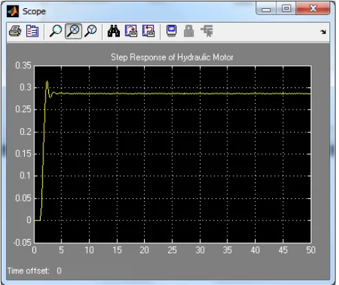
B. SIMULINK Model of Hydraulic Motor
In this SIMULINK model, there are two main portions for hydraulic motor system. They are valve and hydraulic motor portions. The rate limit for that model is to response limitation purpose and the gain 10 is for large response displayed on the scope according to the unit step response for hydraulic motor system. The feedback gain 0.002 is used to limit the feedback signal from the hydraulic motor response to compare with the unit step input for hydraulic motor system.
Fig.4. Screenshot Result for Hydraulic Motor C. SIMULINK Model for Conveyor System
The main part of the conveyor system is the DC servo motor control system. Therefore the stability analysis on the DC servo motor is supported to design consideration of conveyor system. The controller for DC servo motor is the PID controller and it is very efficient controller design for high torque motor control system. According to the gain value for motor, the feedback gain was selected to optimize the performance of the motor control system.
Fig.5. Screenshot Result for Conveyor System
The stable response for DC servo motor could be evaluated by using integrator after conveyor transfer function. The conveyor motor gain can be chosen based on the forwards gain for DC servo motor system.
D. SIMULINK Model for Bottle Filling Robot System The purpose of bottle filling robot system is to carry the rank of bottle from bin to conveyor and from conveyor to bin respectively. The mathematical model for bottle filling robot system is discussed in previous section. There are two main transfer functions to control the bottle filling robot system. They are robot plant and controller stages. The robot plant could be represented by the rotational dynamic of the mechanical arm and the controller is stands for compensation of the robot plant for bottle filling robot system. The disturbance effect has to be considered to evaluate the performance of the bottle filling robot system. The gain value 20 is for simulation results displayed on the scope. The unit step input is very efficient to analyze the dynamic stable of the bottle filling robot system. Figure 6 shows the SIMULINK model for bottle filling robot system.
Fig.6. Screenshot Results for Bottle Filling Robot System
SIMULATION RESULTS
152
Fig.7. Main GUI Window for Bottle Filling Process Control Management
E. Simulation Result of Process Control
Management Using MATLAB
The main GUI window consists of the OPEN and EXIT button to control the filling system process control. The OPEN button covers the actual distributed remote devices for process managements.
Fig.8. Screenshot Result for Overall Simulation Condition After activating the Distributed_Control _System button under OPEN, the process control management window is displayed and the screenshot result for overall simulation condition is illustrated in Fig.8. In this Figure, there are three main portions which are separated by three push buttons. The master terminal unit (MTU), network and remote terminal unit buttons are to control the process stage of bottle filling system. If the master terminal unit button is pressed, the virtual images of
three computers which are connected via industrial Ethernet are displayed in the region of MTU from MATLAB GUI. The network button is for activating with the industrial Ethernet for DCS system. The remote terminal unit is for field level communication and RTUs activation system. There are four main RTUs devices for process control management of bottle filling system. They are PLC remote device, the Hydraulic motor, the conveyor, and the bottle filling robotic system. The dynamic stability response for PLC remote device is illustrated in Fig.9. According to this simulation result, the response curve approaches to one for unit step level after 100millisecond. This duration of process time is very accurate for PLC control process for bottle filling system.
Fig.9. Step Response for PLC Remote Device
153
Fig.10. Step Response for Hydraulic Motor System
Fig.11. Step Response for Conveyor System Output Stage
Fig.12. Comparison Response for Conveyor System Input and Output Stage
The error response for conveyor control system is illustrated in figure 5.10. The maximum overshoot under 7 milliseconds is not affected on the motor performance. Therefore the system is stable at dynamic stage with operating condition.
Fig.13. Error Response for Conveyor System Fig.14 mentions the step response for bottle filling robot system. This response says the dynamic stable at 3 milliseconds and the percent overshoot of this response is very less to accept the dynamic stable condition.
Fig.14. Step Response for Bottle Filling Robot System
CONCLUSION
154 research, a low cost data acquisition, processing and
monitoring system based DCS system has successfully developed. In this thesis motors, sensors and other devices are used and applied to with the help of MATLAB software. It is very low cost for applications and has shown that computers and automated control can be used as a tool to increase product quality and production flexibility. In this research, design and implementation of DCS based bottle filling system process that used MATLAB software. In this project, the conveyor one is moving to send the bottle to the desire location firstly. After arriving the object at the place where already assigned, the robot gripper pick up that bottle to send to filling system process. Thereafter, robot gripper will wait at somewhere to pick up the new bottle. Finishing the filling process via filling machine, the product is taken by the robot gripper to move to packing station. To reach the packing station, robot gripper has to draw the finished object to the next conveyor.
ACKNOWLEDGMENT
The author would like to thank many colleague to complete this work from Mandalay Technological University.
REFERENCES
[1] Ling Wang and Hong-Ying Wei, “Development of a Distributed Control System for PLC-Based Applications”, College of Electronic and Information Engineering, Hebei University, 2010..
[2] Julia Case Bradley, Anita C. Millspaugh, “Programming in Visual C# 2008”, Computer and Information Technology, http://www. primisonline.com, 2009.
[3] Hla Myo Tun, Distributed Control System For Vehicle Spare Parts Manufacturing Plant, Ph.D Thesis, Mandalay Technological University, Mandalay, Myanmar, 2008.
[4] Gareth Talamini, “Operator Interface Design for Industrial Control”, University of Queensland, October, 1997.
[5] Tsourveloudis,N; Ioannidis S.& Valavanis, K, Fuzzy Surplus Based Distributed Control of Manufacturing Systems, USA, APEM Journal. pp-5-12, 2006.
[6] Cole, E., R. Krutz, and J. Connelly. The Network Security Bible. New York: John Wiley & Sons, 2005.
[7] Hugh Jack, “Automation Manufacturing Systems with PLCs”,Person Education, 2005.
[8] Edward W. Kamen, “Introduction to Industrial Controls and manufacturing”, School of Electrical and Computer Engineering Georgia Institute of Technology, 1994.
[9] Beum, H. “Technology Update: Cyber Security Guidance-Interface Technologies,” Control Engineering, June 1, 2004.