Vol. 08, Issue 01 (January. 2018), ||V2|| PP 01-06
A Compact Slots Loaded Disc Patch Antenna For Multiband
Application
*
S. S. Sayeed,Mohd. Gulman,
2M. Kumar,
3K. Jaiswal, J.A. Ansari
Department of Electronics & Communication,University of Allahabad, Allahabad, U.P., India.
Corresponding Author:S. S. Sayeed,Mohd
Abstract
:
The article consists of a novel compact disc patch antenna with S-shaped slot. It is proposed that it operates on multiband covering the applications in WiMAX, WLAN, X-bands and ITU of frequency. The multiband behavior of proposed antenna with a wide band (6.091-7.27) is achieved, mainly due to the appropriate placing of two shorting pins, S-shaped slots on the circular disc patch and the material of the substrate used. The designed antenna operates at resonating frequencies of 2.63 GHz, 3.12 GHz, 4.52 GHz, 6.68 GHz and 8.32 GHz respectively. It is suitable for WiMAX, WLAN, C-band (4-8 GHz) and ITU. The geometry is then simulated using available IE3D software and the results are measured. It is found that the agreements between the simulated and experimental results are very good.Keywords:
Multiband antenna, WIMAX, WLAN, disc, shorting pin, IE3D, ITU (International Telecommunication Union).--- ------ Date of Submission: 12-01-2018 Date of acceptance: 27-01-2018 --- ---
I.
INTRODUCTION
Nowadays, Microstrip patch antenna is very popular due to its merits such as low profile, light weight, inexpensive to manufacture and easy to fabricate. Inspite of these merits, there are demerits like narrow bandwidth, poor power handling capacity in MSA’s (microstrip antennas) [1-2]. MSA’s generally operates at defined frequency band which leads to space-limiting problem. One way to get rid of this problem is using multiple antennas, but this increases system size and complexity. To overcome this problem, multiband antennas are required where the same antenna resonate at different frequencies. Hence it reduces the system size as well as complexity [3].In multi-band MSA’s it is possible that many standards such as GPS (Global positioning system), WIMAX (Worldwide Interoperability for Microwave Access) and WLAN (wireless local area networks) standards can be integrated into a single wireless device. Microstrip patch antennas can be of any shape such as rectangular, circular, triangular or square etc. Microstrip multiband disc patch is applicable for many wireless applications such as S-band (2-4) GHz, C-band (4-8) GHz and X-band (8-12) GHz [4-6]
The diodes, switches, cutting slots of different geometry, multiple narrow slits, stacking, slot antenna with edge fed is used to obtain multiband applications of the antenna [7]. Wide-band or multiband antennas are required for multiservice system [8-11]. Over the past years, several techniques have been reported for multiband antenna design, one of the widely accepted technique to design multiband antenna is loading the radiating patch with a slot [12] appropriately design not only lower the fundamental resonant frequency of the antenna but also leads to dual or wideband operation.There are many techniques which are reported in literatures that obtain multiband behavior such as employing Microstrip line feeds in orthogonal direction and circular disc antenna excited by Y-shape like Microstrip feed [13-14].Also cutting two pairs of orthogonalarrow slits on stacked circular disc exhibits multiband application [15]. Although some of these antenna structures involve complex calculation, sophisticated design structure and large size compared to proposed antenna.In this paper, the proposed antenna consists of S-shape slots on circular patch. The proposed antenna resonates at 2.63 GHz, 3.12 GHz, 4.52 GHz, 6.68 GHz, 8.32 GHz frequencies. The designed antenna is applicable for WiMax, WLAN, C- band application and military communication satellite (uplink) range assigned by ITU [9, 16-17]. The shape of geometry is circular with S-shaped slots on radiating patch fed by co-axial feed. IE3D simulator software, based on MOM (Method of Moments) is used to simulate the result and Vector Network Analyzer is used to measure the result. The measured results show that the proposed antenna operates in multiband behavior. The details of antenna design and results are explained in following section.
II.
ANTENNA CONFIGURATION
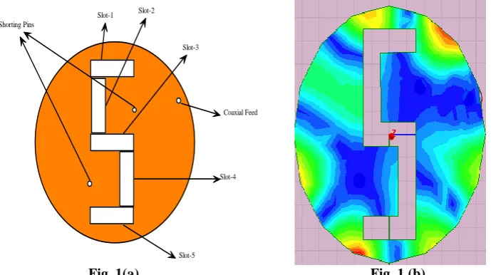
of substrate chosen [27x27] mm of height 1.6 mm.The diameter of circular radiating patch is 22mm. The co-axial feed of 50 ohm input impedance is used to excite the antenna. The slots and shorting pins are introduced in the antenna to generate new resonating frequencies. The front view, side view and 3-D geometry of the antenna is shown in figure 1(a), 1(b) and 1(c). The current distribution shows the radiation mechanism of antenna as shown in figure 2. This antenna provides multiband behavior due to multiple slots and shorting pins on radiating patch. The experimental set up shown in figure 3(a),(b) and (c).
Slot-1 Slot-2
Slot-3
Slot-4
Slot-5
Coaxial Feed Shorting Pins
Fig. 1(a) Fig. 1 (b)
Figure1. The geometry (a), and current distribution using HFSS simulation software of proposed S-shaped circular patch antenna (b).
Coaxial feed Shorting Pins
Circular Disk Patch
Dielectric Substrate
Ground Plane
Figure 2: Side view of proposed antenna
Figure 3: Fabrication of Proposed antenna having (a) Top view, and (b) Bottom view Table-1Design specification of proposed antenna:
Dielectric Material (Substrate) Used FR-4
Dielectric Constant of Substrate Used 4.4
Height of Substrate 1.6mm
Loss Tangent of Substrate Used .02
Radius of Circular Disc patch 11 mm
Location of First Shorting Pin From the centre of circular disc patch
(3.325,3.6)
Location Of Second Shorting Pin (-3.7,-4.05)
Location of Coaxial feed (8.6,3.35)
Length and Width of Slot-1 6mm x 2mm
Length and Width of Slot-2 2mm x 6mm
Length and Width of Slot-3 6mm x 2mm
Length and Width of Slot-4 2mm x 6mm
Length and Width of Slot-5 6mm x 2mm
III.
RESULT AND DISCUSSION
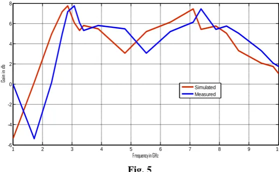
IE3D simulation software is used to simulate the proposed antenna configuration. The return loss of the designed antenna is shown in figure 4(a). The antenna resonates at resonating frequencies of 2.63 GHz, 3.12 GHz, 4.52 GHz, 6.68 GHz, 8.32 GHz with fractional BW of 4.94%, 1.15%, 4.38%, 17.64% and 4.1 %. The designed antenna has multiband behavior with a wideband operation. The range of wideband for this antenna is from 6.091 GHz to 7.27 GHz as shown in figure 4.The gain vs frequency of proposed antenna is shown in figure 5, which concludes that antenna has good gain. The simulated and experimental results are shown figure 5 , and they are in close agreement with each other.
1 2 3 4 5 6 7 8 9 10
-35 -30 -25 -20 -15 -10 -5 0
Frequency in GHz
Re tur n L os s ( db) Simulated Measured Fig. 4
Figure - 4 shows the Frequency vs. Return Loss graph and from the above figure its clear that Simulated result and measured result are in close agreement.
1 2 3 4 5 6 7 8 9 10
-6 -4 -2 0 2 4 6 8
Frequency in GHz
Ga in in db Simulated Measured Fig. 5
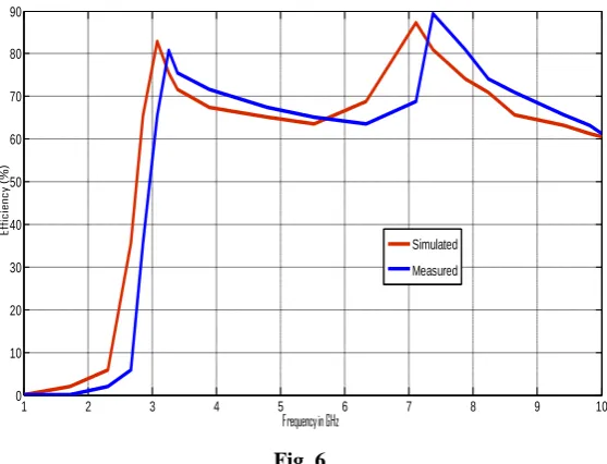
1 2 3 4 5 6 7 8 9 10 0
10 20 30 40 50 60 70 80 90
Frequency in GHz
Effi
ci
enc
y
(%
)
Simulated
Measured
Fig. 6
Figure -6 shows the Efficiency vs. frequency graph. And from the graph its observe that simulated and experimental are in close agreement
.
Fig. 7 (a) Radiation Pattern at 2.63 GHZ Fig. 7 (b) Radiation Pattern at 3.12 GHz
Fig. 7(e) Radiation Pattern at 8.23 Ghz
Figure 7: Radiation pattern of proposed antenna at resonating frequencies such as (a) 2.63 Ghz (b) 3.12 GHz (c) 4.79 GHz (d) 6.3 GHz and (e) 8.23 GHz having E-and H-plane
IV. CONCLUSION
In this article a novel compact slots loaded circular patch antenna has been designed and on introducing the shorting pins and loading the slots on disc patch antenna, the multiband is achieved. It is found that antenna resonates at 2.63 GHz, 3.12 GHz, 4.52 GHz, 6.68 GHz, 8.32 GHz frequencies with fractional bandwidth of 4.94%, 1.15%, 4.38%, 17.64% and 4.1 %. The proposed antenna is capable of satisfying the requirements of WiMAX, WLAN, C-band (4-8) GHz and military communication satellite (uplink) range assigned by ITU respectively.
ACKNOWLEDGEMENT
The author is grateful to University Grant Commission (UGC),India for providing financial assistance.
REFERENCES
[1]. Surendra K. Gupta, Ashish Sharma, Binod K. Kanaujia, Shekar Rudra, Ritu Raj Mishra and G.P. pandey, “Orthogonal slit cut
stacked circular patch Microstrip antenna for Multiband operation”. Microwave Optical Technology letters/ Volume 55, No. 4, April 2013
[2]. L. Shafai, Antenna engineering handbook, McGraw-Hill, NewYork, 2007.
[3]. C.A. Balanis, Antenna Theory: Analysis and Desin, Wiley-Interscience,2012
[4]. Y.F. Caw, S.W. Cheung. Senior Member. IEEE and T.I.Yuk, Member, IEEE, “A Multiband Slot Antenna for GPS/WIMAX/WLAN
Systems”. IEEE Transaction on Antennas and Propagation
[5]. J. A. Ansari, SapnaVerma, and Ashish Singh, “Design and Investigation of Disk Patch Antenna with QuadC-Slots for Multiband
Operations”. Hindawi Publishing Corporation International Journal of Microwave Science and Technology, Volume 2014.
[6]. J. A. Ansari, N. P. Yadav, P. Singh, and A. Mishra, “Compact Half U-Slot Loaded Shorted RectangularPatch Antenna For
Broadband Operation”Progress In Electromagnetics Research M, Vol. 9, 215-226, 2009.
[7]. J.A. Ansari, Anurag Mishra, N.P. Yadav, P.Singh, B.R. Vishvakarma, “ Analysis of W-slot loaded patch antenna for dualband
operation”. Int. J. Electron. Commun. (AEÜ) 66 (2012) 32– 38
[8]. D.N.Elsheakh,H.A.Elsadek,E.A.Abdallah,M.F.Iskander, and H. Elhenawi, “Reconfigurable single and multiband inset feed
microstrip patch antenna for wireless communication devices,” Progress in Electromagnetics Research C,vol.12,pp.191–201, 2010.
[9]. S. Verma, J. A. Ansari, and M. K. Verma, “A novel compact multi-band microstrip antenna with multiple narrow slits,” Microwave
and Optical Technology Letters,vol.55,no.6,pp. 1196–1198, 2013.
[10]. L. Xu, Z. Y. Xin, and J. He, “A compact triple-band for kshaped antenna for WLAN/WiMAX applications,” Progress in
Electromagnetics Research Letters,vol.40,pp.61–69,2013.
[11]. L. Dang, Z. Y. Lei, Y. J. Xie, G. L. Ning, and J. Fan, “A compact microstrip slot triple-band antenna for WLAN/WiMAX
applications,” IEEE Antennas and Wireless Propagation Letters,vol.9,pp. 1178–1181, 2010
[12]. D.D. Krishna, M. Gopikrishna, C.K. Anandan, P. Mohanan, and K.Vasudevan, Compact dual band slot loaded circular microstrip
antenna with a superstrate, ProgrElectromagn Res 83 (2008), 245–255.
[13]. J. P. Thakur, J.-S. Park, B.-J. Jang, and H.-G. Cho, “Smallsize quad band microstrip antenna,” Microwave and Optical Technology
Letters ,vol.49,no.5,pp.997–1001,2007.
[14]. J. Pei, A.-G. Wang, S. Gao, and W. Leng, “Miniaturized triple-band antenna with a defected ground plane for WLAN/WiMAX
applications,” IEEE Antennas and Wireless Propagation Letters, vol. 10, pp. 298–301, 2011.
[15]. S.K.Gupta,A.Sharma,B.K.Kanaujia,S.Rudra,R.R.Mishra,andG.P.Pandey,“Orthogonalslitcutstackdcircularpatchmicrostrip antenna
International organization of Scientific Research 6 | P a g e
[16]. Pratap N. Shinde∗, Jayashree P. Shinde, Design of compact pentagonal slot antenna with bandwidth enhancement for multiband
wireless applications. Int. J. Electron. Commun. (AEÜ) 69 (2015) 1489–1494.
[17]. Amit Singh Bhadouria, Mithilesh Kumar, Multiband DGS Based Microstrip Patch Antenna
[18]. For Open Satellite Communication,978-1-4799-6393-5/14/$31.00 ©2014 IEEE
[19]. HFSS simulator version 15, Ansoft Corporation, Pittsburg, Pa, USA
[20]. Zeland Software, IE3D Simulation Software, Version 14.05, Zeland Software, 2008.