Improving The Efficiency Of I.C. Engine Using
Secondary Fuel
A.Vamshi Krishna Reddy, T.Sharath Kumar, D.K. Tharun Kumar, B. Dinesh, Y.V.S. Saisantosh
Mechanical Department Malla Reddy College of Engineering, JNTUH, Hyderabad, India; 5Aeronautical Department Malla Reddy College of Engineering, JNTUH, Hyderabad, India.
Email: [email protected]
ABSTRACT: The rapid depletion of fossil fuels and rising of oil prices has led to the search for Secondary fuels. The Secondary fuels that we are using should have the same efficiency or greater efficiency of the engine that uses ordinary fuel. In this project the secondary fuel used is HHO gas. HHO otherwise known as hydroxyl or Browns Gas is the gas produced from splitting water into hydrogen and oxygen from electrolysis and allowing the gas to stay in a premixed state for use on-demand without the need for storage. This reduces the exhaust gas emitted during the working of engine, and the temperature of the engine is also reduced which is produced by the burning of ordinary fuels. The HHO gas is injected into the inlet manifold of the combustion chamber through the air filter of the engine. From this design the fuel utility is reduced from 10% to 30% which minimizes the carbon deposition in the cylinder thereby increasing the changing period of engine oil, it also improves the efficiency of the engine and the life span. Engine torque also increased and pollution gets reduced to maintaining the green house effect.
Keywords :Fuel;I.C. engines;Efficiency;Pollution;HHO
1
I
NTRODUCTIONA LTERNATE fuel is important and it should be fossil one. Ac-tually we spend one third of our income for our vehicle fuelling and the vehicle gives harmful decomposed materials like CO, NOx, HC, WCBSFC, etc...in the form of smoke. These mate-rials are all affects the engine performance, and pollutes the environment. Compare to other kinds of fuel around the world, water is one of the free recourses and by applying the tech-nique, it can be converted into hydrogen with oxygen, its chemical term is HHO and in general “Free Energy”. It is cheaper, safer, tremendous explosive and never pollutes the atmosphere. While crossing a gas or diesel operated car we can feel the smell of the respective fuels, it shows that the fuel is not completely burnt. It is explicit that we waste fuel and pollute the atmosphere. To avoid these drawbacks, some level of HHO is mixed with filtered air, which is after the air filter sys-tem and before the engine in taken syssys-tem of the car. This mixed HHO ignites releasing the extra electrons into the ignit-ing fuel and thus the added extra energy from the HHO leads cent percent of complete burning of the fuel. The HHO has Polymorphism that is it acts differently - before burning, while burning, and after burning. Before burning of Hydrogen, which is a lightest gas with one proton and one electron and more efficient fuel three times of the explosive power when camper to fuel gas and five times than petrol. Actually, the Hydrogen requires little bit of energy of ignition to produce wide level of tremendous flammable temperature in the speed of lighting and there is no chance to compare with other fuel in this world. As a result of fact it increases the engine performance, torque, and millage and minimums fuel consumption. During burning the HHO into the engine with a tremendous explosion on that area and gives off high power of energy and automatically re-verts to water vapour at once. Due to this action the engine not only getting higher torque but also gets easily cooled from 10 to 20 times faster than other fuels. For example after combus-tion of fuel in the engine the level of temperature is approx-imately 250oF, but on the other hand mixing of HHO with same fuel means the engine temperature reduces approximately from 150oF to 200oF only because of vapours formations after combustion. Thus the engine life period gets wider, and reduc-es lubricating oil degradation beyond the limit of Km. Then oil changing period also gets lengthened. It leads in decrease of
the maintenance cost and increase of interval of maintenance. After burning the HHO, the engine gives steam and some per-centage of oxygen on the exhaust side and the stream is au-tomatically converted into water form in the atmosphere. Thus the exhausts emission also controls from 10% to 50%. The pollution also reduces and remaining Oxygen comes out from the exhausts.
2
I
NTERNALC
OMBUSTION ENGINEThe internal combustion engine is an engine in which the combustion of a fuel (normally a fossil fuel) occurs with an oxidizer (usually air) in a combustion chamber that is an integral part of the working fluid flow circuit. In an internal combustion engine (ICE) the expansion of the high-temperature and high-pressure gases produced by combus-tion apply direct force to some component of the engine. The force is applied typically to pistons, turbine blades, or a nozzle. This force moves the component over a distance, transforming chemical energy into useful mechanical energy. The first commercially successful internal combustion engine was created by Etienne Lenoir. The term internal combustion en-gine usually refers to an engine in which combustion is inter-mittent, such as the more familiar four-stroke and two-stroke piston engines, along with variants, such as the six-stroke pis-ton engine and the Wankel rotary engine. A second class of internal combustion engines use continuous combustion: gas turbines, jet engines and most rocket engines, each of which are internal combustion engines on the same principle as pre-viously described. The ICE is quite different from external combustion engines, such as steam or Stirling engines, in which the energy is delivered to a working fluid not consisting of, mixed with, or contaminated by combustion products. Working fluids can be air, hot water, pressurized water or even liquid sodium, heated in a boiler. ICEs are usually powered by energy-dense fuels such as gasoline or diesel, liquids derived from fossil fuels. While there are many stationary applications, most ICEs are used in mobile applications and are the domi-nant power supply for cars, aircraft, and boats.
2.1 Classification I.C. engines
the cylinder. This heat is added to the air inside the cylinder and thus the pressure of the air is increased tremendously. This high pressure air moves the piston which rotates the crank shaft and thus mechanical work is done.
2.1.1 Based on fuel used
Diesel engine –Diesel is used as fuel Petrol engine – Petrol is used as fuel
Gas engines– propane, butane or methane gases are used
2.1.2 Based ignition of fuel
Spark ignition engine (Carburetor type engines) Compression ignition engine (injector type engines)
2.1.2.1 Spark ignition engine
A mixture of air and fuel is drawn in to the engine cylinder. Ig-nition of fuel is done by using a spark plug. The spark plug produces a spark and ignites the air- fuel mixture. Such com-bustion is called constant volume comcom-bustion (C.V.C.).
2.1.2.2 Compression ignition engine
In compression ignition engines air is compressed in to the engine cylinder. Due to this the temperature of the com-pressed air rises to 700-900 0C. At this stage diesel is sprayed in to the cylinder in fine particles. Due to a very high tempera-ture, the fuel gets ignited. This type of combustion is called constant pressure combustion (CP.C.) because the pressure inside the cylinder is almost constant when combustion is tak-ing place.
2.1.3 Based on working cycle 2.1.3.1 Four stroke cycle engine
When the cycle is completed in two revolutions of the crank-shaft, it is called four stroke cycle engines.
2.1.3.2 Two stroke cycle engine
When the cycle is completed in one revolution of the crank-shaft, it is called two stroke cycle engines.
2.2 Construction of an I.C. Engine
I.C. engine converts the reciprocating motion of piston into rotary motion of the crankshaft by means of a connecting rod. The piston which reciprocating in the cylinder is very close fit in the cylinder. Rings are inserted in the circumferential grooves of the piston to prevent leakage of gases from sides of the piston. Usually a cylinder is bored in a cylinder block and a gasket, made of copper sheet or asbestos is inserted between the cylinder and the cylinder head to avoid ant lea-kage. The combustion space is provided at the top of the cy-linder head where combustion takes place. The connecting rod connects the piston and the crankshaft. The end of the con-necting rod concon-necting the piston is called small end. A pin called gudgeon pin or wrist pin is provided for connecting the piston and the connecting rod at the small end. . The other end of the connecting rod connecting the crank shaft is called big end. When piston is moved up and down, the motion is trans-mitted to the crank shaft by the connecting rod and the crank shaft makes rotary motion. The crankshaft rotates in main bearings which are fitted the crankcase. A flywheel is provided at one end of the crankshaft for smoothing the uneven torque produced by the engine. There is an oil sump at the bottom of the engine which contains lubricating oil for lubricating different
parts of the engine.
2.3 Working Principle of I.C. Engine
A mixture of fuel with correct amount of air is exploded in an engine cylinder which is closed at one end. As a result of this explosion, heat is released and this heat causes the pressure of the burning gases to increase. This pressure forces a close fitting piston to move down the cylinder. The movement of pis-ton is transmitted to a crankshaft by a connecting rod so that the crankshaft rotates and turns a flywheel connected to it. Power is taken from the rotating crank shaft to do mechanical work. To obtain continuous rotation of the crankshaft the ex-plosion has to be repeated continuously. Before the exex-plosion to take place, the used gases are expelled from the cylinder, fresh charge of fuel and air are admitted in to the cylinder and the piston moved back to its starting position. The sequences of events taking place in an engine are called the working cycle of the engine. The sequence of events taking place in-side the engine is as follows
1) Admission of air or air-fuel mixture inside the engine cylinder (suction)
2) Compression of the air or air fuel mixture inside the engine (compression)
3) Injection of fuel in compressed air for ignition of the fuel or ignition of air-fuel mixture by an electric spark using a spark plug to produce thermal power inside the cylinder (power )
4) Removal of all the burnt gases from the cylinder to re-ceive fresh charge (exhaust)
Note: Charge means admitting fresh air in to the cylinder in the case of compression ignition engines (diesel engines) or admitting a mixture of air and fuel in to the cylinder in the case of spark ignition engines.
2.4 Four Stroke Cycle Engine
In four stroke cycle engines the four events namely suction, compression, power and e xhaust take place inside the engine cylinder. The four events are completed in four strokes of the piston (two revolutions of the crank shaft). This engine has got valves for controlling the inlet of charge and outlet of exhaust gases. The opening and closing of the valve is controlled by cams, fitted on camshaft. The camshaft is driven by crankshaft with the help of suitable gears or chains. The camshaft runs at half the speed of the crankshaft. The events taking place in I.C. engine are as follows:
Fig.2.4.1 Four stroke cycle engine
Fig.2.4.2 Four stroke cycle engine 2.4.1 Suction stroke
During suction stroke inlet valve opens and the piston moves downward. Only air or a mixture of air and fuel are drawn in-side the cylinder. The exhaust valve remains in closed position during this stroke. The pressure in the engine cylinder is less than atmospheric pressure during this stroke.
2.4.2 Compression stroke
During this stroke the piston moves upward. Both valves are in closed position. The charge taken in the cylinder is pressed by the upward movement of piston. If only air is com-pressed, as in case of diesel engine, diesel is injected at the end of the compression stroke and ignition of fuel takes place due to high pressure and temperature of the compressed air. If a mixture of air and fuel is compressed in the cylinder, as in case of petrol engine, the mixture is ignited by a spark plug.
2.4.3 Power stroke
After ignition of fuel, tremendous amount of heat is generated, causing very high pressure in the cylinder which pushes the piston downward (Fig.1b). The downward movement of the piston at this instant is called power stroke. The connecting rod transmits the power from piston to the crank shaft and crank shaft rotates. Mechanical work can be taped at the
rotat-ing crank shaft. Both valves remain closed durrotat-ing power stroke.
2.4.4 Exhaust stroke
During this stroke piston moves upward. Exhaust valve opens and exhaust gases go out through exhaust valves opening. All the burnt gases go out of the engine and the cylinder becomes ready to receive the fresh charge. During this stroke inlet valve remains closed (Fig.1d). Thus it is found that out of four strokes, there is only one power stroke and three idle strokes in four stroke cycle engines. The power stroke supplies neces-sary momentum for useful work.
2.5 Two Stroke Cycle Engine (Petrol Engine)
In two stroke cycle engines, the whole sequence of events i.e., suction, compression, power and exhaust are completed in two strokes of the piston i.e. one revolution of the crankshaft. There is no valve in this type of engine. Gas movement takes place through holes called ports in the cylinder. The crankcase of the engine is air tight in which the crankshaft rotates.
Fig.2.5.1 Two stroke cycle engine
Fig.2.5.2 Two stroke cycle 2.5.1 Upward stroke of the piston
op-posite to each other. This traps the charge of air- fuel mixture drawn already in to the cylinder. Further upward movement of the piston compresses the charge and also uncovers the suc-tion port. Now fresh mixture is drawn through this port into the crankcase. Just before the end of this stroke, the mixture in the cylinder is ignited by a spark plug (Fig 2 c &d). Thus, dur-ing this stroke both suction and compression events are com-pleted.
2.5.2 Downward stroke (Power + Exhaust)
Burning of the fuel rises the temperature and pressure of the gases which forces the piston to move down the cylinder. When the piston moves down, it closes the suction port, trap-ping the fresh charge drawn into the crankcase during the pre-vious upward stroke. Further downward movement of the pis-ton uncovers first the exhaust port and then the transfer port. Now fresh charge in the crankcase moves in to the cylinder through the transfer port driving out the burnt gases through the exhaust port. Special shaped piston crown deflect the in-coming mixture up around the cylinder so that it can help in driving out the exhaust gases. During the downward stroke of the piston power and exhaust events are completed.
3
S
OCIETALI
MPACTSO
FS
ECONDARYF
UELThe intended transition from the use of gasoline and other fossil fuels as “mass” fuels, to hydrogen and electricity to pow-er most automobiles, is predicted to considpow-erably reduce the detrimental consequences of fossil fuels on the environment. One of the primary negative effects is global warming. But what effect will this change have on the individual and on the society as a whole? How do these bio-friendly fuels measure up to fossil fuels in other areas? This chapter discusses the potential negative consequences of alternative fuels in the areas of pollution, health, safety, and annual expenses. This encompasses the effects of a large scale migration to bio-friendly fuels on the individual as well as the society at large. A comparison is also drawn between the polluting substances from conventional fossil fuel driven vehicles as against those from a few alternative environment friendly fuels.
3.1 Safety of the Individual
This is a cause of concern during accidents in pure electric and hybrid electric cars, since they are designed to be light to compensate for the low power provided by an electric motor compared to an internal combustion motor, as well as provide a longer travel range on a single charge-up. A drawback of a light weight chassis and frame is reduced safety for the occu-pants in the event of an accident. In the case of serious acci-dents, the cost of healthcare becomes an issue for society as well as the owner of the electric car. There is a higher likelih-ood of injury as the structure of the car is weaker. To cite an example, the average annual total cost of spinal cord injuries vary from $16,792 for a thoracic incomplete spinal cord injury to $28,334 for a cervical complete spinal cord injury. This data is the result of the average cost measured across 675 spinal cord injury patients in the USA. The average yearly health care and living expenses vary greatly according to the severity of the injury. First-year injury costs range from $218,504 for incomplete motor function at any level, to $741,425 for high tetraplegia injuries. Thus it is apparent that jeopardizing the safety of the occupants can come at a much higher cost when considered from the individual occupant’s point of view. A safety concern associated with the widespread use of
hydro-gen and other compressed fuels such as Compressed Natural Gas is the on-board storage of fuel in a tank. Appropriate ma-terials for use in compressed tanks need to be developed and thoroughly tested until they can be extensively used in ve-hicles sold to the public. Even if the tanks are placed safely behind the occupants and surrounded by a framework, the fear of them exploding always exists, since some hydrogen tanks are compressed up to 10,000psi. The potential danger increases in an accident, when the tanks may be struck due to the framework around them being damaged, causing a cata-strophic explosion. The next section presents the dangers posed to society by the use of four types of environment friendly fuels.
3.2 Dangers Posed to Society Categorized by Fuel 3.2.1 Compressed Natural Gas
Since CNG is stored at a pressure of 2900psi in vehicles, there is a danger of explosion of the tank. There is also the possibility of undesired escaping of gas, which could very easily ignite, causing an explosion. Another danger is the possible re-ignition of gas after a fire is extinguished. In order to recognize these dangers, measuring equipment is used to monitor the pressure and flow of gas along with other parame-ters to ensure regulated levels. An artificial odor is added to the otherwise odorless natural gas to help detect leaks. Other safety devices installed to keep these dangers in check in-clude electromagnetic valves, which are mounted at each gas tank and will close the tank in case of an accident or when the engine or the ignition is turned off. A release limiter will also reduce the amount of gas that can be released in case of a leak in the gas lines. A built in pressure relief device opens the tank in case of intensive heat to avoid an increase in pressure that could lead to an explosion of the gas tank. Other safety procedures to prevent accidents involve keeping the gas tank at a safe distance from the passenger compartment, and avoiding ignition sources. The vehicle should be well venti-lated, and if the gas ever ignites, the burning gas should not be extinguished.
3.2.2 Hydrogen (internal combustion engine)
should be avoided, and burning gas should not be extin-guished. The vehicle should be well ventilated.
3.2.3 Hydrogen (fuel cell)
Dangers associated with these kinds of vehicles consist of leaking of battery pack materials. Since electricity is used to power the vehicle, it could conduct to undesired locations which are hazardous to the occupants. Also, it is important to monitor the status of the electric motor during the course of its operation. Safety devices used here include power cutoff switches to handle power surges. One problem associated with fuel cell powered vehicles is that it is difficult to detect faults and possible dangers in the electricity generation and drivetrain. Safety procedures to avoid accidents involve immo-bilizing the vehicle by deactivating the drivetrain as soon as a potential source of danger is diagnosed. Also, there should be no unauthorized tampering with the battery or any other com-ponents. Electrical cables that carry high current are colored bright orange or blue so their detection is easy.
Fig.3.2.3 Method of production of electricity in a hydrogen fuel cell
3.2.4 Hybrid
These vehicles combine the advantages of both internal com-bustion as well as electric-powered vehicles. As a result, there are also the disadvantages that come with both types of en-gines when it comes to the aspect of safety. The high voltage of about 42V to 450V supplied by the battery pack poses a high risk if any of the components malfunction. However, safe-ty devices are built in that shutdown the vehicle when an acci-dent is detected. Capacitors inside the hybrid system could keep a residual current for a few minutes after the system is shutdown. All electrical components with a higher current are normally marked bright orange so they can be easily identified. Another danger involved with electrically-powered vehicles is that their running status cannot be identified easily; that is it is difficult to tell whether the car has been switched on or not. The safety precautions followed here are the same as those on hydrogen fuel cell vehicles. These are immobilizing the vehicle by deactivating the drivetrain, and observing extra cau-tion when handling the battery and other drive train compo-nents.
3.3 Pollution and Costs
This section will help obtain a broader understanding of the long term societal and environmental effects of using different types of fuels. The costs and pollution involved in producing and using five different types of fuels is analyzed, along with their negative effects on the environment and as a result on human beings. These five basic fuels are conventional
gaso-line, other hydrocarbons such as LPG and CNG, hydrogen, and electricity. The methods of producing hydrogen in a fuel cell are also discussed, along with the pollutants associated. The analysis will be performed based on the energy required to propel an average automobile 100 miles at a constant speed of 50 miles/hr. The fuel efficiency at this speed is ap-proximately 27 miles/gal, which implies that 3.7 gallons of fuel are used for this distance at 50 miles/hr. The energy contained in 3.7 gallons of gasoline is 132.87 kWh, since the energy density of gasoline is 34.2MJ/L. Thus an approximation can be made for the amount of energy required using this data for gasoline. It is assumed that for LPG, CNG and hydrogen, the energy conversion efficiencies in a vehicle are the same as for gasoline.
3.3.1 Conventional Gasoline
Crude oil prices were close to their all time high in the year 2008, leading to gasoline prices of $3.25/gallon. Using data for this year, the price of a gallon of regular gasoline can be bro-ken up into Cost of crude oil (69%), Federal and state taxes (13%), Distribution and marketing (12%), and Refining costs and profits (7%).
Fig.3.3.1 Price breakup of gasoline
From this data, profits make up about 4% of the total price of gasoline. Since 3.7 gallons of gasoline are required for 100 miles at the given speed, the cost of 3.7 gallons or 14 liters of gasoline as of 2008 was $124. Out of this 4% or 48 cents are contributed towards profits for the company. This neglects other costs such as maintenance and capital investments in gas stations, but these will be ignored for the purpose of this analysis since they depend on factors such as how long the gas station was in service and the location of the gas station. This assumption is made uniformly across the analysis for consistency. From a pollution point of view, the carbon dioxide emitted from the average gasoline powered vehicle is 190g CO2/km, which results in overall CO2 emissions of 30,571g over a 100 mile range.
3.3.2 Liquefied Petroleum Gas - Propane
pres-sure at which the liquid is stored in the containers in an auto-mobile 7 and 9 bars or about 115 psi. The liquefying tempera-ture is -42.1 °C.
Fig.3.3.2 Propane production and distribution schematic Since the energy density of propane LPG burned in air is 7kWh/L, 19 liters or 5 gallons of propane LPG are required to propel the car 100 miles. At current prices in the USA for commercial propane LPG, 5 gallons will cost $10.4510. The percentage profit for the manufacturer of propane is about the same at 4%. This implies a profit of 42 cents for the manufac-turer. Since typical LPG cars emit about 145 gCO2/km, the total CO2 emissions from an LPG over a 100 mile range is 23,330g. In Table 1 below, the only pollutant released at an increased rate is methane; whose emissions are increased by 10% when propane is used as a fuel.
Table 3.3.2 Propane vs. Gasoline emissions 3.3.3 Compressed Natural Gas
CNG is much safer than most other alternative fuels since it is lighter than air; so in the event of a spill it disperses easily. It is stored and dispersed in hard containers at a pressure of 2900-3200psi. The cost of a gallon of CNG in the USA is about $1.78. The energy density of CNG burnt in air is 2.5kWh/L. Thus the volume of CNG required to take the average car 100 miles is 14 gallons. The total cost of this amount of fuel for the consumer is $25. The profit for the company is then $1, as-suming a 4% profit rate. Since the emissions from using CNG as a fuel are 143gCO2/km, the total emissions are 23,008gCO2 over a 100 mile range.
Fig.3.3.3.2 – Estimated efficiencies using hydrocarbon fuels
3.3.4 Hydrogen (internal combustion engine)
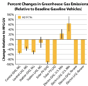
There are two types of hydrogen-powered vehicles. In the type analyzed in this report, stored or on-board produced hydrogen is used as fuel in an internal combustion engine to power the vehicle. The other type of hydrogen-powered vehicle uses hydrogen to produce electricity in a fuel cell that powers an electric motor. These vehicles are also equipped with batteries that store the electricity that cannot be used by the motor im-mediately. From this data, the energy density of liquid hydro-gen is 10.1MJ/L or 2.81kWh/L. Thus 47.3 liters or 12.51 gal-lons of hydrogen are required to drive the car 100 miles. At current rates of hydrogen available ($9.45/gal), 12.5 gallons of hydrogen would cost $118.22. Since accurate information re-garding the breakup of the cost of one gallon of hydrogen is not easily available, one can assume the profit for the manu-facturer to be about 10% of the selling price since there are no refining costs involved. However, transportation and storage costs are high since the hydrogen is highly compressed at up to 10,000psi. A profit rate of 7-10% of the selling price results in $8.28 - $11.82 of profit for the company, when enough hy-drogen to propel a car 100 miles is sold. This is obviously very uneconomical for the consumer, and although the profit figures for the company are steep, they are used to recover the high capital investment made to set up a hydrogen manufacturing plant as will be seen later on. An alternative method to solar power can be used to obtain the required electricity to electro-lyze hydrogen from water, such as nuclear power. The cost of electricity from a nuclear power plant is around 12 cents/kWh. The energy required to produce, compress and store 1 liter of hydrogen is 1.75kWh. This would cost 21 cents when using electricity produced in a nuclear power plant. Since 47.3 liters of hydrogen or 82.8kWh of energy is being used here, the cost of electricity is $9.94. Since the CO2 emissions when obtaining electrical energy from nuclear power is 66 gCO2/kWh, the total CO2 emissions are 3,953g when a car travels 100 miles. Fig-ure3.3.4 presents the percentage increase or decrease of greenhouse gas emissions of hydrogen manufactured by vari-ous methods, in comparison to emissions from gasoline.
Fig.3.3.4 Pollution advantage of H2 over gasoline 3.3.5 Hydrogen (fuel cell)
following are the reactions that occur when octane combusts using oxygen from the air:
2C8H18 + 25O2 16CO2 + 18H2O
2C8H18 + 17O2 16CO + 18H2O
On the other hand, the reaction that occurs when a hydrogen fuel cell produces energy from H2 and oxygen in the air is:
2H2 + O2 2H2O
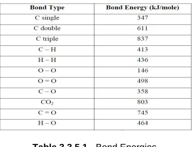
Table 3.3.5.1 shows the bond energies of the various bonds involved in these reactions:
Table 3.3.5.1 - Bond Energies
Using the information in this table, the energies released per mole in each step of the reaction can be calculated. The dif-ference in energies between the products and the reactants in the gasoline combustion reaction is 42400 – 32176 = 10224 kJ/mole. This means that the energy released per H atom pro-duced is 10224/36 = 284 kJ/mole, and the energy released per fuel mass is 10224/228 = 44.84 kJ/mole. On the other hand, the difference in energies of products and reactants in the hy-drogen fuel cell reaction is 1856 – 1370 = 486 kJ/mole. The energy released per H atom is the same as the energy re-leased per fuel mass which is 486/4 = 121 kJ/mole. To sum-marize the calculations, the gasoline reaction releases 2.35 times as much energy per hydrogen atom, and 0.37 times as much energy per fuel mass when compared to the hydrogen fuel cell reaction. The mass ratio of water released per unit mass of gasoline used is 1.4, and for hydrogen it is 9. Thus, for equal masses of gasoline and hydrogen, the hydrogen fuel cell releases 2.35 as much water per unit mass as compared to gasoline combustion. Since the ignition temperature of gas-oline is around 260°C, the water released is in vapor form. The water vapor and the carbon dioxide released are harmful greenhouse gases. Since the operating temperature of hydro-gen in the fuel cell is 50 – 250 °C, all the water released is either as a hot liquid or low temperature steam. This is not an environmental hazard. Next, a comparison will be drawn be-tween the annual emissions from an average car running on gasoline versus hydrogen. These emissions will then be re-lated to their corresponding harmful effects on humans, ani-mals and the environment.Table 3.3.5.2 below assumes that the average car travels 12,500 miles/year with a fuel con-sumption rate of 22.5 miles/gallon.
Table 3.3.5.2 - Pollutants from gasoline Cars
Fig.3.3.5 - Pollutant Chart
4
E
XTRACTIONO
FHHO
4.1 Extraction of HHO from Water:
An HHO Generator utilizes electric current to break up into water into hydrogen and oxygen. The electricity enters the water on the left side at the “cathode” (a negatively charged electrode). The electricity passes through the water and exists via the “anode” (the positively charged electrode), shown on the right side. Hydrogen can be collected at the cathode, while Oxygen can be collected at the anode. It is also possible to let these gases mix on their way out and this combined gas is what we call HHO.
4.1.1 Chemical Transformation:
The chemical transformation of water to HHO is best de-scribed in the figure displayed below. It shows the atoms of oxygen (O) and hydrogen (H) are being transformed from the well known H2O which we know as LIQUID WATER-into a new arrangement of atom pairs. Now these pairs are in GAS form. Two separate gases, not water vapour. The atom pairs we see on the right side of the diagram are in the “forth state of water” mentioned above. That’s HHO. Brown's Gas is a mixed gas of hydrogen and oxygen (2:1, by volume) created by electrolysis of water. It is thought that Brown's Gas also contains consi-derable water vapor. Generally, electrolysis of water produces a hydrogen gas at the cathode and an oxygen gas at the anode. These gases are captured at the same time without being separated, and the captured mixed gas is generally known as “Brown's Gas.” Brown's Gas has several characte-ristic properties, unlike its constituent gases. The most notice-able property of Brown's Gas is implosion upon ignition. For this reason, Brown's Gas is known to have ultra-high tempera-ture to an extent that can sublimate [change directly from solid to vapor without first melting] tungsten – a metal that has the highest melting point of all metals! HHO is different than pure hydrogen (and significantly more powerful); by volume, it has 3 times more energy than gasoline but HHO is not used as stand-alone fuel. It is a best alternate supplement to any fuel-it makes any hydrocarbon fuel (liquid or natural gas) perform more work. It is stressed that HHO is supplemental to regular fuel. Another difference: we never store HHO-it must be pro-duced on-demand and used right away. HHO is considered a clean burning fuel because there been no pollutants and the energy been released and turns back to original state of water. The stated following reasons clearly show the characteristics: HHO is a produced and utilized and may not be stored (unlike hydrogen, methane, propane and natural gas which must be stored in problematic pressure tanks). When gasoline is spilled, it creates a fire hazard for a long time due to its slow evaporation rate. But HHO is lighter than air, diffuses rapidly in the air (without adding any pollutants!) and since it has a high initial flammability limit, it is safer than other combustible gas-es. HHO is an environmentally friendly fuel that returns to wa-ter when combusted and does not pollute the environment-and reduces pollution of fossil fuel combustion-a great safety point for passengers and workers. The way it interacts with all hy-drocarbon fuels, HHO cause temperature of lower ignition point to the overall operation conditions of a vehicle's engine or any stationary generator/compressor.
4.1.2 HHO Practical Principles:
HHO mixes with the atmospheric air coming into the engine, and then, inside the air/fuel mixture, it helps the fossil fuel burn
completely. That’s all it does! Its gaseous fuel additive that you add into the air stream rather than the liquid fuel. HHO is not Stand-alone fuel (in our use).It can be described in this way also:
Fig.4.1.2.1 - HHO = IGNITER of Unburned Fuel According to “Advanced technologies and energy efficiency, Fuel Economy Guide” published by the U.S. Department of Energy in 2009, the modern automobile engine is only 18.2% efficient. After drive line losses, you have only 12.6% to drive with. At the top of the diagram we see that we lose 17.2% to standby/idling time. That’s due mainly to driving conditions and there’s little we can do about that. At the bottom of the diagram you can see that the ENGINE is the greatest energy waster at 62.4%.
4.1.3 Gasoline versus Water:
The thermo chemical energypresent in water as such as gas-oline. The DOE (Department of Energy) has quoted about 40%, so it is probably much more than that. Most people are unaware that "internal combustion" is defined as "a thermo-vapour process"-as in "no liquid in the reaction." Most of the gasoline powered internal combustion engine consumes cooked and finally broken down in the catalytic converter after the fuel has been not-so-burnt in the engine. Technically, it is much safer than running on fossil fuel there been no longer choking on own emissions (health-wise). The simple safety devices been used according to current automotive standards.
4.1.4 Production of HHO:
max-imum amount of energy out of it (this is a small time window), once the piston starts going down the energy transfer from the explosion to engine becomes less efficient. The Oxy hydro-gen’s higher burn temperature and explosive force is such that it cleans the soot that collects in the engine and with a cleaner engine we can get better mileage and fewer oil changes.
4.2 HHO as an additive:
Hydrogen is highly explosive at standard temperatures and pressures when mixed with air. There are eight layers of safe-ty redundancy in the hydrogen system making it almost im-possible even to cause any injuries.
4.2.1 Small volume of HHO storage:
The hydrogen and oxygen are produced on demand, so the only storage is in the supply lines and the gas void in the elec-trolyte tank and molecular sieve. The maximum storage/worst case scenario is around 1L stored in the bubbler flash back arrestor. The energy in 1L of HHO could be calculated as the HHV of the stored volume of hydrogen.
Mass of hydrogen in 1L at STP;
mh2
T
R
MW
v
p
.
.
.
mg
X
X
X
X
0
.
55
15
.
298
3145
.
8
016
.
2
10
667
101325
6
Where, mH2 is the mass of hydrogen
p is the pressure of air [Pa] V is volume of gas [m3]
MW is the molecular weight of hydrogen [g mol-1]
R is the ideal gas constant [J K-1 mol-1] T is the temperature [K]
Energy in 1 liter of HHO in terms of the product of the higher heating value of hydrogen (HHVH2);
EH2 = mH2 X HHVH2
= 55.0 X 10-6 X 141.86 X103 =7.8 kJ
Where, HHVH2 is the higher heating value of hydrogen [J/g]
This is the equivalent to the energy contained in 0.17g of di-esel.
4.2.2 No ignition source inside system.
There are no spark energy sources inside the HHO system. The control of HHO production being open loop, so there are no sensors in the HHO supply or production zones.
4.2.3 High auto ignition temperature of 585°C
The hottest part of the exhaust pipe was measured at 440 under full load, so this is ~140 below the flammability limit. There is no mechanism to allow HHO to be vented to the ex-haust manifold in any case of failure.
4.2.4 Leak tested
The system was tested for hydrogen flow at the electrolyte tank and then at the bubbler where the gas leaves the sys-tem. The seals in the flash back arrestor where leak proofed with Vaseline for easy of servicing.
4.2.5 Hydrogen is highly dissipative
Hydrogen is 14 times lighter than air risingat 20m/s.
4.2.6 Room ventilation
USQ’s engine laboratory is fully ventilated, even if it was sealed the hydrogen would dissipate out of the room quicker then it could be produced.
4.2.7 Emergency stop isolation:
The emergency stop button (E-stop) breaks power to the di-esel supply valve, and makes a separated isolated contact to the PLC control system. On activation the DC electrical supply to the water electrolyser is isolated, preventing an more production of HHO. The main supply relay is supplied from generators 24V DC PLC power supply, which is only active when the engine is running.
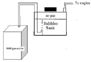
4.3 HHO Generator
The distilled water will be required because tap water can have metal in that will rust the plates. We will also have to add an electrolyte to the water to speed up the electrolysis. It is important to control the electrolysis, because a simple genera-tor can be built without PWM which be similar to an engine with only the possibility of full throttle. The HHO pulse width modulator is necessary for a controlled electrolysis. The spe-cific frequency and power for the most efficient electrolysis wires from generator to generator. A HHO generator uses electric current to separate water into its hydrogen and oxy-gen. A generator consist of water in which cathode and anode is dipped with a little amount of Potassium Hydroxide (KOH) is added as a catalyst. The electricity enters the water at the cathode passes through water and via the anode. Hydrogen can be collected at cathode and oxygen at anode. The bottom of the device is the jar and then the remaining be constructed on the plastic cap with the jar lid. The lid carries the Bubbler Cap (1) that lets atmospheric air and regulates the bubbling, electrical terminal (2) and (3) that let the electric power which propagates into electrodes (5).The electrodes are stainless steel wires which be wrapped with an acrylic “tower” (the red part inside the jar)-it can be any colour you like, There is also Valve (4) which is for safety, and one or two output Valves (6). The output hoses are two short, usually 6” long pieces of va-cuum hose.
4.3.1 Major Parts of HHO Generator
Electrolyser: This unique design has RECTANGULAR elec-trodesplates. It is stored in a quart-size highly durable jar.
4.3.2 Material selection to design electrodes:
There are different materials could be used as an electrode. But each one has its own merits and demerits .From the over-all search the selection of material for electrodes should be stainless steel thicker in size. The electrodes shape is either in plate or tube form. The numbers of electrode depends on our gas requirements. The distance between each plate should be minimum and should have equal space all over the arrange-ment of electrodes. There are two methods of arrangearrange-ments of electrodes - without-neutral and with-neutral. The without-neutral electrodes construction consists of number of positives P and negatives N plates which are all arranged alternatively, example if there are three set of positive and negative elec-trodes then P-N-P-NP- N is the arrangement. Next with-neutral electrodes construction consists of number of positives P ,neutral Nu ,and negatives N plates which are all arranged in the following manner Nu-N-Nu-Nu-Nu-N,or , P-Nu-Nu- P-Nu-Nu-N-P-Nu-Nu-P-Nu-Nu-P-Nu-Nu-P-P-Nu-Nu-P-Nu-Nu-P-Nu-Nu-N, etc… The purpose of neutral plate is to prove better cooling effect while electro processing. Here the neutral plates are also of the same ma-terial and same size .But in this work the former one has been selected and designed as P-N-P-N-P-N. For the connectivity among positive electrodes and negative electrodes, they are arranged not to make any shot circuit at any condition and mechanically should be strong to withstand the electrolyte cor-rosions.
4.3.3 Material selection to design a container
The container should have the following properties as follows: should withstand chemical corrosion, mechanical stress and strain, tremendous vibration and temperature. If it is transpa-rent, it is easy to check the electrolyte level and its color and it should be a gas tight container, because HHO is a light weight gas compared to air. On the top of the container there are five holes as shown in figure two holes in opposites are for positive and negative terminal, one hole for gas outlet through gas hose.Within the container up to top of the electrode either rain water or distilled water with a very little amount catalysts are added, because pure water will not conduct electricity. In this model of HHO tank one liter of distilled water with required amount of KOH (potassium hydroxide) is added as a catalysts.
4.3.4 Vaporizer
The purpose is to include water vapour to theengine and cool it down with improvement in combustion and fuel economy. It can be used with tap water or with a mixture of water and addi-tives.
4.3.5 Selection Of Catalysts
The catalysts may be pinch of salt or White Vinegar (H3C-COOH) or Baking Soda (NaHCO3) or Sodium Hydroxide (NaOH) or Potassium Hydroxide (KOH) or Potassium Carbo-nate (K2CO3). Each catalyst has its own merits and demerits. As per the requirement the requirement the catalyst is chosen; otherwise it gives more heat with more gas but consumes more DC current from the vehicle battery. Density of electro-lyte is directly proportional to current consumption.
4.3.6 Designing of Bubble Bottle
Bubbler is otherwise called safety bubbler or collector, which has a simple arrangement. The container should be flexible and withstand the vibration and little bit pressure, transparent and should have feet of height.
Fig.4.3.6.1 - Single Bubbler arrangement.
These all conditions are satisfied by a simple water bottle made of plastic. With the incoming and outgoing plumbing works are as shown in figure 4.3.6.1, then it is called Bubbler. The three fourth of the bubbler should filled with water. The gas incoming tube from the HHO generator should be dipped into bottom of the water level always. For that purpose the side of the tube is pasted up to bottom level of the bottle with little gap to let gas bubbles from the tube to the top of the wa-ter level. The outgoing tube should be at the top of the bottle top. These arrangements should be a gas tight one. This bubbler solves two important problems as the generated HHO bubbles are washed and avoid the chemicals from electrolyze to flow into engine and another important function is protection of flashback effect. Instead of single bubbler we may use more bubbler for our safety and cleaning the HHO brown gas as shown in figure 4.3.6.2.
4.4 Safe Alternatives to Baking Soda
Sodium Citrate which is basically citric acid: A safe food in-gredient used in ice-cream, cheese and wine. Possible sources: ice cream/beverage manufacturers, food supplies, etc. You may find it under other names: Citrosodine, Tri-Sodium Citrate, Citric Acid (PURE citric acid, no sugar please!), or Tri-Sodium Salt. Washing Soda is a laundry de-tergent that might be found under the names of Soda Ash, Laundry Soda, Sal Soda, or Sodium Carbonate. Used as a non-toxic all-purpose cleaner-look in the laundry section of your grocery store. Borax is also used for laundry and might be known as Sodium Borate, Sodium tetra borate, or Dis-odium Tetra borate. It is NOT boric acid.
4.5 Control valve
Fig.4.5 – Control valve
Connects between the generator and the engine's vacuum intake and feeds the hydroxyl gas into the engine and can be able to control the flow of the gas.
4.6 Fuse holder + Electrical Wiring:
Fig.4.6 – Electrical wiring with battery clips
Connects the 12 volts battery to the HHO generator which helps to produce required amount of gas through the genera-tor.
4.7 Mechanical Installation Hardware
Bungee cords, cable straps, flex tubing which was used for fitting the generator beside the engine.
5
T
ESTINGT
HEP
ERFORMANCEO
FD
IESELE
NGINEW
ITHHHO
G
AS5.1 Introduction
Diesel engines are widely used for various applications chang-ing from agriculture to automobiles. Engines are required to be tested mainly for two purposes- firstly, on production line of engines; engines are tested to check the proper operation, output, fuel consumption etc. And secondly, in research of de-sign purposes, where the performance of new dede-sign to be evaluated. The dynamic apparatus consists of a single cylind-er; vertical diesel engine mounted over a sturdy frame, loading arrangement used is rope break which is connected to engine
through a coupling. A digital multichannel temperature indica-tor measures temperatures at various points. Various mea-surements provided enables to evaluate the performance of the engine at various loads.
5.2 Specifications 5.2.1 Engine
Single cylinder, vertical, water-cooled self governed diesel engine, developing 5HP @ 1500 r.p.m.
5.2.2 Brake
Rope break with spring balances and loading screw. Break drum diameter = 0.270 meters.
Belt thickness = 0.006 meters. Effective radius = 0.138 meters.
5.2.3 Measurements
i Calibrated fuel burette for fuel consumption mea-surement.
ii Orifice meter, fitted to air inlet tank with water mano-meter for air intake measurement.
iii Multichannel digital temperature indicator for tempera-tures at various points.
iv Exhaust gas calorimeter to measure heat carried away by exhaust gases.
5.2.4 Testing procedure
i Check oil level in the engine. It should be up to the top of the flat portion provided over the oil dipstick. If oil level is reduced, add up clean SAE-40 oil to the crank case by opening the valve cover at the top of the engine. Replace the cover after filling the oil. ii Fill up sufficient amount of diesel in tank.
iii Start the water supply and see that the water is flow-ing through engine jacket, brake drum and exhaust gas calorimeter. Put off the water in the break drum. iv If diesel tank was empty before filling the diesel,
re-move air bubble in fuel pipe, by opening the vent screw, provided at the right side, top of the fuel pump. v Release the loading screw so that there is no tension
in the rope.
vi Lift up decompression lever at the side of the valve cover, put the handle over the starting shaft and ro-tate the shaft. As engine picks up sufficient speed, drop the decompression lever. The engine will start. Remove the handle immediately.
vii As engine picks up speed, start water to the break drum.
viii Load the engine with loading screw and set the spring balance differences to, say 2kgs.
ix Open burette filling cock, take sufficient diesel in bu-rette and close the cock.
x Now, turn selector cock to burette position and note down time required for 10ml fuel consumption. xi Note down break drum speed with tachometer and
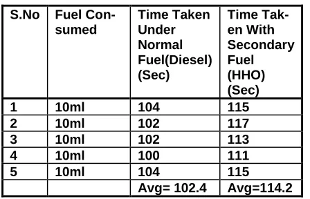
5.2.5 Comparing time taken for consuming 10ml of fuel with and without HHO in Diesel engine
S.No Fuel Con-sumed Time Taken Under Normal Fuel(Diesel) (Sec) Time Tak-en With Secondary Fuel (HHO) (Sec)
1 10ml 104 115
2 10ml 102 117
3 10ml 102 113
4 10ml 100 111
5 10ml 104 115
Avg= 102.4 Avg=114.2 Table 5.2.5 – Comparing time for consuming 10ml of fuel with
and without HHO in diesel engine
Under normal conditions average time taken for 10ml of fuel consumption is 102.4sec
Using HHO gas the average time taken for10ml of fuel con-sumption is 114.2sec
So we save 11.8sec for every 10ml of fuel consumption
For our convenience,
Ordinary fuel consumed i.e. normal conditions 1ml = 10.24sec
This can be converted to lit/hr i.e.
(10.24 X 1000)/3600 = 3.28lit/hour
Similarly for HHO gas
11.8sec for every 10ml
1180sec for every liter
In terms of liter/hour = 3.05 liter/hour
Therefore, (3.28 – 3.05) = 0.23lit is being saved for an hour. In terms of fuel that is being saved 23 X 60 = 1380sec = 1380/11.42 = 120.8ml.
So we save 108ml for every liter of fuel i.e., 12.08% of fuel is saved.
In terms of rpm (under no load conditions): Under normal conditions = 600rpm Using HHO gas = 618rpm
5.2.6 Performance test on four stroke diesel engine by mechanical loading using diesel only
Table 5.2.6 Performance test on four stroke diesel engine by mechanical loading using diesel only
5.2.7 Performance test on four stroke diesel engine by mechanical loading using the HHO gas
Table 5.2.7 Performance test on four stroke diesel engine by mechanical loading using the HHO gas
5.3 Calculations i Brake power –
1000
60
2
X
NT
BP
Where,
N= Break speed, rpm = 1580 rpm T= Torque, N-m
= (L X 9.81) X 0.141 Nm = (4 X 9.81) X 0.141 = 5.34 Nm
ii Fuel consumption –
Let time required for 10ml fuel be tf sec, & density of diesel is 0.851 gms/cc. S.n o Fuel con-sump tion (kg/h r) Brak e pow-er (kW) Specif-ic fuel con- sump-tion (kg/kw. hr) Indi-cated pow-er (kW) ŋm (%) ŋbt (%) ŋit (%)
1 0.25 0.43 0.58 1.13 38 14. 5
38. 1
2 0.31
2 0.91 0.34 1.61 56 24 43. 5 3 0.36 1.35 0.266 2.05 65 32 48
4 0.50 1.73 0.28 2.43 71.
1 29 41
5 0.63 2.31 0.27 3.01 76 30 40. 3 S.n o Fuel con-sum ption (kg/h r) Brak e pow er (kW) Spe-cific fuel con-sum ption (kg/k w.hr) Indi-cate d pow er (kW) ŋm (%) ŋbt (%) ŋit (%)
1 0.18 0.42 0.43 1.12 37.5 13.2 39.3
2 0.26 0.91 0.28
6 1.61 56.5
2 22.8 42.5
3 0.30
9 1.35 0.22
8 2.05 65.8 31.6 47 4 0.42 1.73 0.25 2.43 71.1 30.5 43
5 0.57 2.30 0.23 3.0 76.6
kg/hr . . kg/hr f t . . X X f t FC 312 0 90 08 28 08 28 78 0 1000 3600 10 Where,
tf = time for 10ml fuel to be consumed = 90 sec.
iii Specific fuel consumption –
hr kw kg hr kw kg BP FC
SFC 0.34 / .
91 . 0 312 . 0 . /
iv Heat supplied by fuel –
HF = FC X 42630 KJ/hr. = 0.312 X 42630 = 13300.56 kJ/hr.
Where, calorific value of diesel is 42630 KJ/kg
v Plot graph of FC vs. BP for different readings. Extend the line to meet zero FC. The power (on negative side) at which FC is zero is friction power, FP.
FP = 0.7
vi Indicated power IP = FP + BP kW
= 0.7 + 0.91 = 1.61 KW
vii Heat Equivalent to BP – HBP = BP X 3600 kJ/hr.
= 0.91X 3600 = 3276 kJ/hr.
viii Heat Equivalent to IP – HIP = IP X 3600 kJ/hr.
= 1.61 X 3600
= 5796 kJ/hr
ix Mechanical efficiency.
% 56 100 61 . 1 91 . 0 %
100
X X
IP BP m
x Break thermal efficiency –
% 100 X fuel by Supplied Heat BP in Heat BT % 24 100 24 . 0 56 . 13300 3276 X
xi Indicated thermal efficiency –
% 5 . 43 100 56 . 13300 5796 %
100
X X
F H IP H BT
6
C
ONCLUSIONHHO gas technology is still considered experimental but it is a supplemental fuel additive of sorts that could help you in-crease mileage, inin-crease horsepower, reduce emissions while providing a quieter and cleaner engine. Energy must be con-served in one way or other so we are trying to implement this in the future. This might be a good plan to save the environ-ment.It is clear from the various investigations and analyses that hydrogen has the potential to be a very promising eco-friendly fuel. Harmful emissions are almost negligible when compared to gasoline and other fossil fuels, and there is no cause of concern relating to the sustainability of the fuel as hydrogen is a vastly abundant element. Uniform and improved mixing of hydroxyl-air and oxygen content of HHO stimulate combustion which has a major effect on SFC by using an ade-quate capacity system. Wide flammability range, high flame speed and short quenching distance of hydroxyl yield diesel fuel to be combusted completely under high speed conditions and low speed conditions.
7
R
EFERENCES[1]. “Method Of Obtaining Hydrogen From Steam”, http://www.miningtopnews.com/fuelcell-energy- announces-new-process-to-produce-hydrogen-from-gas.html [2]. http://www.gas4free.com/?hop=cbank83706 [3]. http://www.hhogasgenerator.com/ [4]. http://www.academia.edu/4058265/HHO_and_Diesel_Tec hnology
[5]. Review of Advanced Marine Vehicles Concepts Apostolos Papanikolaou, National Technical University of Athens, Ship Design Laboratory, Greece (NTUA-SDL)
[6]. Electric and Hybrid Vehicles design Fundamentals-Iqbal Hussain CRC press.
[7]. Gomez de Silva, J. and S. Ron, 1993. Tonatiuh, the Mex-ican Solar Race Car. A vehicle for technology transfer. SAE Special Publications, pp: 63-67.
[8]. Seal, M.R., 1995. Viking 23-zero emissions in the city, range and performance on the freeway. Northcon-Conference Record 1995. IEEE, RC-108, pp: 264-268.