A Low Cost Oil Extraction Machine for
Extraction of Oil from Gears
Siddhesh Nanaware Prasanna Gondhale
B.E. Graduate B.E. Graduate
Department of Mechanical Engineering Department of Mechanical Engineering STES NBN Sinhgad School of Engineering, India STES NBN Sinhgad School of Engineering, India
S. D. Kemkar Sandeep Nanaware
Ph. D Student Engineer
Department of Physics Delphi Powers Pvt. LTD., Smt. Chandibai Himathmal Mansukhani College, India Pune, India
Abstract
This work illustrates a low cost mechanical system manufactured for extraction of oil which is present on gears when the gear is under manufacturing process. The sedimentation principle under centrifugal force is used as a basic principle in this system for removal of oil. The gear is spun at 1440rpm for 4 seconds for extracting oil. The centrifugal forces acts tangentially to the gears and is responsible for the removal of oil from the gears. This oil is collected in the oil pot and then supplied by tubes to the oil filter. Oil filter is used for filtration of oil coming from the oil pot. The filtered oil is again supplied for hobbing and shaving machines thus recycling and making it reusable. Similar setup with different dimensions can be used for different gears.
Keywords: Hobbing, Spindle, Shaft, Centrifugal force, R cube, Gear
________________________________________________________________________________________________________
I. INTRODUCTION
Nowadays R cube (Recycle, Reuse, Reduce) is a need for better environment, therefore it is always researched where recycling or reduction or reuse can be done and various techniques are thought of for the same. This work presents a machine with similar aim of recycling and reuse.
Gear manufacturing process involves basically hobbing of a blank [1]. Firstly, the gear blanks are passed to ID checking machine for internal diameter checking. After verification, these gears are passed to hobbing machine where gear cutting operation is done. During gear cutting operation, oil is sprinkled on the gear blanks for the reason of heat dissipation, precision cut, flowing out the burr and appropriate gear cutting. After gear cutting, these gears are passed to the DOP (Diameter Over Pin/ Dimension Over Pin) checking machine for measurement of diameter over pin [2]. For this measurement, the oil present on the gears is being removed by using cotton threads or waste cloths; sometimes gears are thoroughly washed. Thus, there is wastage of oil. Instead, this oil can be collected and reused by recycling it in appropriate processes like hobbing and shaving of gears. By installing this gear spinning machine and using it immediately after the hobbing process, the oil can be collected and thus recycled for further use; resulting in reduction of oil consumption, thus leading to reduction in overall cost of production and also improving the process efficiency and environmental harm.
II. EXPERIMENTAL SETUP
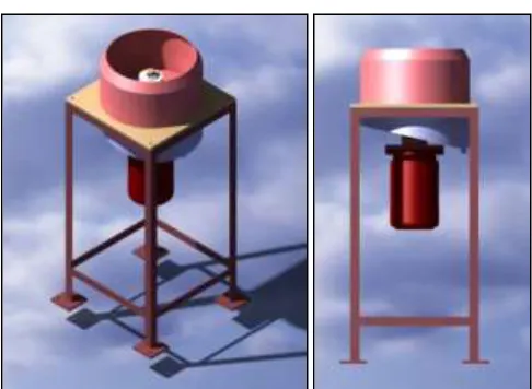
The experimental setup consists mainly of, a main frame, barrel, fixture, spindle, oil pot, motor shaft, electric motor, supply lines, filter as shown in Figure. This setup extracts and collects the oil from the surface of the mounted gear and filters it for further usage and can also calculate the quantity of the oil.
Fig. 1: Experimental Setup of Oil extraction by Gear Spinning machine
Detail of the Setup is provided in the CAD drawing below.
Fig. 2: CAD drawing of the setup
III. PARTS
Main Frame
The main frame has the function of supporting all the components and absorbing the vibrations produced during operation of the machine. The main frame has to be rigid enough to support all parts and withstand the different forces acting on the system such as rotating force of shaft and spindle, vibrational forces, etc; thus made of Cast Iron [4]. Rubber pads are placed at the bottom of the pillars of the main frame to provide grip to the structure and for absorbing vibrations.
Oil Pot
Fixture
Fixture is a work-holding device used in manufacturing industries. A fixture's primary function here is to create a secure mounting point for the gear, helping for support during operation and increased accuracy [5]. Fixture needs to be designed or selected as per the size of the gear to be used.
Fig. 3: CAD Drawing of Fixture
Base Plate
The base plate is fixed to the frame. The base plate acts as a base for the fixture and the cover and these both components are fixed to the base plate. The upper side of the base plate is coated with polytetrafluoroethylene.
Fig. 4: CAD Drawing of Base plate
Gear Spinning Cover
The Gear Spinning Cover is a cover for the fixture and the gear. When the gear rotates, the oil will splash and stick to this cover and then flow down to the oil pot. Inner side of the cover is coated with polytetrafluoroethylene, due to its properties like low friction, adhesiveness etc. [6]
Indusction Motor
Motor is an electrical machine that converts electrical energy into mechanical energy. In normal operating mode, most electric motors operate through the interaction between an electric motor’s magnetic field and winding currents to generate force within the motor. Electric motors are used to produce linear or rotary force (torque) and should be distinguished from devices such as magnetic solenoids. Induction motor used for this machine is rated at 0.5hp at 1440 rpm. Reason for using 0.5hp motor is that it has enough torque to spin a gear and fixture for the time it takes to clean gear completely and it also efficient to work with. Total load induction motor has to bear is less than 1kg
Bearing
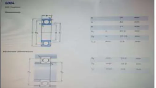
A mechanical element that constrains relative motion to only the desired motion, and reduces friction between moving parts Bearing calculations:-
P = X Fr + Y F a
Neglecting self-weight of carrier and gear assembly Where,
Fr = 250 N and 𝐹𝑎= 40 N As, Fr< e, X = 1, Y = 0
P = 250 N
Calculating dynamic load capacity of bearing [7],
L = (𝐶) 𝑛
(𝑃)𝑛 Where,
n=3 for ball bearings.
For m/c used for eight hr of service per day; LH = 15000 hr
But;
L =60 N LH
106 Where,
N = 1440 rpm, 𝐿𝐻= 15000 L= 1296 million rev
Now;
1296 = (𝐶)
3
(250)3
C= 2725.68 N
As the required dynamic capacity of bearing is less than the rated dynamic capacity of bearing; Bearing is safe.
Bush Coupling
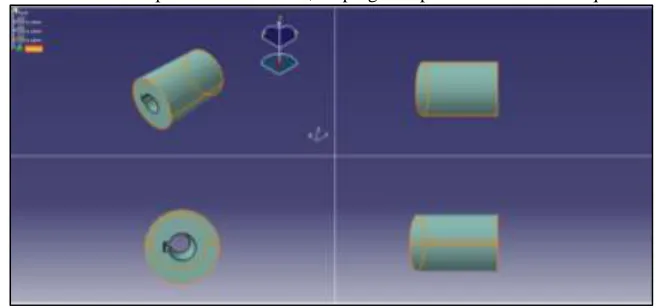
The Bush coupling is used to connect the spindle to the motor, helping the spindle to transmit torque to the fixture.
Fig. 7: CAD drawing of coupling bush
Spindle
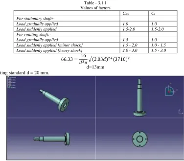
Spindle/Shaft is used to transmit torque from the motor to the fixture. Thus, Shaft Calculations:
Axial Stress [8],
σ = 4αF
πd²(1 − K2)
𝜎 = 1
1 − 0.0044(𝐾𝐿)
𝜎 = 1.0965 N/mm2
Where,
K- Ratio of inner to outer dia. of shaft d- Outer dia. of the shaft
F- Axial force (tensile or compressive) - Column action force
Stress due to torsion,
τ = 16T
πd³(1 − 𝐾4) Where,
T = Torque on the shaft
T =60 × 0.5 × 746
2π × 960
= 3710 N-mm
τ = Ssy
F. O. S.
=0.9 × 380 3 = 63.33 N/mm2
The shafts are normally acted upon by gradual and sudden loads. Hence, the equation is modified in ASME code by suitable load factors,
Where, C
Table - 3.1.1 Values of factors
Cbm Ct
For stationary shaft:-
Load gradually applied 1.0 1.0
Load suddenly applied 1.5-2.0 1.5-2.0
For rotating shaft:-
Load gradually applied 1.5 1.0
Load suddenly applied [minor shock] 1.5 - 2.0 1.0 - 1.5 Load suddenly applied [heavy shock] 2.0 - 3.0 1.5 - 3.0
66.33 = 16
𝑑3𝜋√(2.03𝑑)2+(3710)2 d=13mm
Therefore, selecting standard d = 20 mm.
Fig. 8: CAD drawing of Spindle
Motor Mounting Plate
The motor is mounted and fixed on this plate which is in turn connected to the spindle housing.
Fig. 9: CAD Drawing of Motor Mounting Plate
IV. WORKING
1) The gear after the hobbing process is taken as it is and fixed on the fixture.
2) The gear is then rotated at 1440 rpm for 4 seconds and the oil thus splashes on to the cover. 3) This oil then flows down through the perforations and gets collected into the slotted oil pot.
V. CONCLUSION
The machine will help reduce the oil usage for gear manufacturing by extracting and collecting it from the gear, recycling and reusing it; and will improve the process efficiency. The reduced oil consumption leads to reduction of the manufacturing cost of the gears. As the oil is recycled, the need for new oil is reduced which leads to conservation of natural oil resources. Similar setup can be substituted for gear of any appropriate dimensions.
ACKNOWLEDGEMENT
Authors gratefully acknowledge Mr. Shantanu Khole, Department of Quality Control, TATA Motors ltd, Pimpri, India for their help in design development
REFERENCES
[1] Dennis Gimpert, Gear Fundamentals – The gear Hobbing process, pg- 40.
[2] ANSI/AGMA 2002-B88, “Tooth Thickness Specification and Measurement,” pp. 17–23, 1996. [3] Benjamin Crowell, Light and Matter, Chapter 9, section 9.1.
[4] H. T. Angus, Cast Iron Physical and Engineering Properties, Butterworths, Second edition, pg 47, 1976.
[5] Colvin, Fred H.; Haas, Lucian L. Jigs and Fixtures: A Reference Book. New York and London, McGraw-Hill Book Company, pg 3, 1938. [6] D.H. Kaelble, K. C. Uy, A Reinterpretation of Organic Liquid-Polytetrafluoroethylene Surface Interactions, pg 50-60, 08 March 2008 [7] V. B. Bhandari, Design of Machine Elements, The McGraw Hills Companies, Second edition, pg 574, 2008.