ISSN (e): 2250-3021, ISSN (p): 2278-8719
Vol. 08, Issue 12 (December. 2018), ||V (II) || PP 74-80
MATLAB Simulation of Perturb and Observe (P&O) Method of
Maximum Power Point Tracking (MPPT) in Solar Photovoltaic
System (SPV)
Rohit Kumar
1, Risha Dastagir
21Research scholar, Department of Electrical and Electronics Engineering, Trinity Institute of Technology &
Research, Bhopal, India
2
Associate Professor at department of Electrical and Electronics Engineering, Trinity Institute of Technology & Research, Bhopal, India
Corresponding Author:Rohit Kumar
Abstract:
As compare to fossil fuels solar power is everlasting supply of energy whereas fossil fuels and traditional sources of power are restricted. currently solar power or solar photovoltaic’s (PV) gaining a lot of attention of the researchers and market players of this field. Maximum power point tracking (MPPT) is that the optimum answer to extract maximum SPV generated power. MPPT is nothing but the tracking of maximum available power of an SPV system by means of the DC-DC converter. Presently so many methods are available for MPPT operation of solar photovoltaic (SPV). In this paper simulation of SPV along with the Perturb and Observe (P&O) method of MPPT is presented. The mathematical modeling of SPV array and the most popular MPPT technique that is P&O and its implementation is presented in this paper.--- --- Date of Submission: 29-11-2018 Date of acceptance: 13-12-2018 --- ---
I.
INTRODUCTION
A SPV power generation system consists of numerous components like cells, electrical connections and power conditioning unit to regulating and/or changing the electrical outputs. These systems are rated in peak watts (Wp) which is an amount of electrical power that a SPV system can deliver at standard test conditions (STC). Photovoltaic comprises the technology to convert sunlight directly into electricity. The term photo means light and voltaic electricity. A PV cell, also known as solar cell is a semiconductor device that generates electricity when direct or indirect solar radiation falls on it.
II.
MODELING OF PV SYSTEM
The output of PV cell is a function of photon current that can be also determined by load current depending upon the solar insolation during its operation equation [2].
sh s pv pv T s pv pv s T s pv pv s ph pv R R I V V N R I V I V N R I V I I
I
exp 1 exp 1
2
2
…(1)
Fig. 1. Equivalent circuit of a two diode model of a PV cell [1-2].
Where:
Iph is the solar induced or photon generated current:
Iph= Iph0 Ir
Ir 0 ……… (2)
I
ris the irradiance (light intensity or insolation) in W/m2falling on the cell.I
ph0is the measured solar-generated current for the standard irradianceIr0
.I
sis the saturation current of the first diode.V
Tis the thermal voltage,V
T=kT/qk
is the Boltzmann constant.T
is thesolar cell operating temperature.q
is the elementary charge on an electron.N
is the quality factor (diode emission coefficient) of the first diode.N
2is the quality factor (diode emission coefficient) of the second diode.V
pvis the voltage across the solar cell electrical ports.The PV panel output is also dependents on solar insolation and temperature. A solar array modeled on the basis of two diode model has been given in MATLAB. Solar array given in MATLAB library is used for modeling and simulation. Fig. 2 shows the solar array available in MATLAB.
Fig. 2. Solar PVarray available in MATLAB.
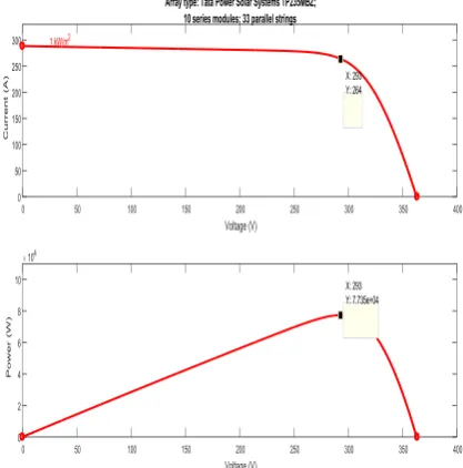
The solar PV array given in MATLAB database is model Tata Power Solar Systems TP235MBZ; 10 series modules; 33 parallel strings. Its parameters are given in Table-I.
Table no 1: Parameters of Solar Module used for Simulation in MATLAB Simulation data: Performance at standard test conditions, STC: 1000 W/m2, 25 °C. Nominal Power PMPP of module 234.4 W
Short Circuit current Isc of module 8.74 A Open Circuit Voltage Voc of module 36.3 V
VMPP of module 29.3 V
IMPP of module 8 A
Table 2: Parameters of Solar Array Obtained from Simulation. Simulation data: Performance at standard test conditions, STC: 1000 W/m2, 25 °C.
Nominal Power PMPP of array 77.35 kW
VMPP of array 293 V
IMPP of array 264 A
III.
MAXIMUM POWER POINT TRACKING
I-V and P-V characteristic shown in Fig 3 shows that the maximum available power of a solar PV system can only deliver to a particular voltage i.e. 293 Volt (VMPP), also with changing environmental condition
this point of voltage (VMPP) vary. There is number of methods or algorithms have been developed for the MPPT
over the past decade. They differ from each other on the basis of variable used for developing MPPT methods. Commonly used variables in MPPT algorithms are: PV current, PV voltage, output current, and output voltage. Based on these variables, there are various methods of MPPT as listed below:
Constant voltage a. Constant Current b. Curve fitting c. Pilot cell d. look up table e. P&O
f. Incremental conductance g. Temperature based h. Beta
i. DC link capacitor droop control j. Current Sweep
Commonly used method is found to be Perturb and Observe (P&O) method P&O algorithms are widely used in MPPT because of their simple structure and the few measured parameters which are required. The algorithm or principal of this method for finding the MPPT is developed by analysing the P-V characteristics of Solar PV array. In this method, the array terminal voltage is perturbed i.e. incremented and decremented and the power output of the array is observed. If the power output of the PV array is increased with the increment in the voltage that means the array is reaching towards the MPP and the perturbation is continued in the same direction, otherwise the perturbation direction will be reversed, hence array terminal voltage is perturbed every MPT cycle; therefore when the MPP is reached, the P&O algorithm will oscillate around it resulting in a loss of PV power, especially in cases of constant or slowly varying atmospheric conditions.. The operation explained in Table I.
Table 3: Methodology of P&O method Perturbation Change in power Next
perturbation Positive Positive Positive
Positive Negative Negative
Negative Positive Negative
IV.
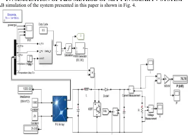
SIMULATION OF P&O METHOD OF MPPT IN SOLAR PV SYSTEM
MATLAB simulation of the system presented in this paper is shown in Fig. 4.Fig. 4: MATLAB simulation of P&O MPPT algorithm applied to a standalone solar PV system
V.
RESULT AND DISCUSSION
The simulated results are presented in this section. Simulation at fixed environmental conditions: The standard test conditions considered are i.e. 1000 W/m2 insolation and 250C temperature. Fig. 5 shows the insolation falling on solar PV array with time. The operating temperature of solar PV array with time is shown in Fig. 6.
Fig. 5.Insolation on solar PV array with time Fig. 6: Operating temperature if solar PV array with time
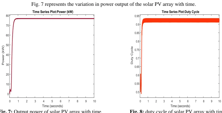
Fig. 7 represents the variation in power output of the solar PV array with time.
Fig. 7: Output power of solar PV array with time Fig. 8: duty cycle of solar PV array with time
According to the P&O operation the duty cycle increases upto the maximum power point after that it oscillate around the point of maximum power. Fig. 8 shows the relation between duty cycle and time and it is clear from the figure that the duty cycle oscillates once the maximum power achieved. Fig. 9 shows the terminal voltage of solar PV array and it is clear from the figure that the voltage of array settled down around the VMPP.
Fig. 10 shows the output current of solar PV array and it is observed that the current of array settles down around IMPP.
Fig.9:Voltage of solar PV array with time Fig. 10: Current of solar PV array with time
VI.
CONCLUSIONS
This paper concerns with implementation of MPPT algorithm in MATLAB, for maximum power extraction. The input voltage is settled near to VMPP where solar PV delivers maximum power. With the help of
duty cycle driven by the P&O is kept corresponding to maximum power point and results show that the MPPT operation is achieved successfully under fixed as well as varying environmental conditions.
REFERENCES
[1]. Verma Deepak, Nema Savita,Nema RK, “Implementation of Perturb and Observe Method of Maximum Power Point Tracking in SIMSCAPE/MATLAB” IEEE International Conference on Intelligent Sustainable Systems ICISS 2017
[3]. Sebri, Maamar, Ousama Ben Salha, “On the causal dynamics between economic growth, renewable energy consumption, CO2emissions and trade openness, Fresh evidence from BRICS countries,” Renewable and Sustainable Energy Reviews 2014, vol. 39, pp. 23-14.
[4]. International Energy Agency, “Tracking Clean Energy Progress,” Paris, France 2014.
[5]. International Energy Agency, “World Energy Investment Outlook - Special Report Paris,” France 2014. [6]. International Energy Agency, “World energy outlook. Paris,” France 2013.
[7]. Mads Troldborg, Simon Heslop, Rupert l Hough, “Assessing the sustainability of renewable energy technologies using multi-criteria analysis, Suitability of approach for national-scale assessments and associated uncertainties,” Renewable and Sustainable Energy Reviews 2014, vol. 39, pp. 1184-1173. [8]. Benson, Christopher l, Christopher l Magee. “On improvement rates for renewable energy technologies,
Solar PV, wind turbines, capacitors, and batteries,” Renewable Energy 2014, vol. 68, pp. 751-745. [9]. lesourd, Jean-Baptiste. “Solar photovoltaic systems, the economics of a renewable energy resource,”
Environmental Modelling & Software 2001, vol. 16 no.2, pp. 156-147.
[10]. Dincer, Furkan. “The analysis on photovoltaic electricity generation status, potential and policies of the leading countries in solar energy,”.Renewable and Sustainable Energy Reviews 2011, vol. 15.1, pp. 720-713.
[11]. Parida, Bhubaneswari, S Iniyan, RankoGoic. "A review of solar photovoltaic technologies," Renewable and sustainable energy reviews 2011, vol. 15.3, pp. 1625-1636.
[12]. Singh Solanki Chetan. “Solar photovoltaics, fundamentals, technologies and applications,” PHI learning Pvt. ltd., 2011.
[13]. Amarnath, R.K. Nema, Deepak Verma, “Modeling and Simulation of Solar Photovoltaic Application Based Multilevel Inverter with Reduced Count Topology for Stand-alone System.” Electrical & Computer Engineering: An International Journal (ECIJ) 6 (2017):1-12
[14]. Das, Soubhagya K., Deepak Verma, Savita Nema, and R. K. Nema. "Shading mitigation techniques: State-of-the-art in photovoltaic applications." Renewable and Sustainable Energy Reviews 78 (2017): 369-390.
[15]. Verma Deepak, Nema Savita, and Shandilya A M. "A different approach to design non-isolated DC–DC converters for maximum power point tracking in solar photovoltaic systems." Journal of Circuits, Systems and Computers 25, no. 08 (2016): 1630004.
[16]. Verma Deepak, Nema Savita, Shandilya A M, and Dash Soubhagya K. "Maximum power point tracking (MPPT) techniques: Recapitulation in solar photovoltaic systems." Renewable and Sustainable Energy Reviews 54 (2016): 1018-1034.
[17]. Dash Soubhagya K, Nema Savita, Nema R K, and Verma Deepak. "A comprehensive assessment of maximum power point tracking techniques under uniform and non-uniform irradiance and its impact on photovoltaic systems: A review." Journal of Renewable and Sustainable Energy 7, no. 6 (2015): 063113. [18]. Verma Deepak, Nema Savita, Shandilya A M and Dash Soubhagya K. "Comprehensive analysis of
maximum power point tracking techniques in solar photovoltaic systems under uniform insolation and partial shaded condition." Journal of Renewable and Sustainable Energy 7, no. 4 (2015): 042701.
[19]. Verma Deepak, Nema Savita, Shandilya A M, and Dash Soubhagya K. "MATLAB (SIMSCAPE) simulation and experimental validation of solar photovoltaic system for performance analysis under varying environmental and mismatch condition." Electrical and Electronics Engineering: An International Journal (ElElIJ) 4, no. 3 (2015).
[20]. Kumar Nikhil, Suresh Gawre, Verma Deepak, and Tushar Kumar. "Physical design and modeling of 24V/48V DC-DC boost converter for solar PV application by using SIMSCAPE library in MATLAB." International Journal of Applied Control, Electrical and Electronics Engineering (IJACEEE), Wireilla Publication, Australia 2, no. 2 (2014).
[21]. Kumar Nikhil, Gawre Suresh K and Verma Deepak. “Harmonics mitigation of P&O MPPT based solar powered neutral point clamped multilevel inverter.” International Journal of Applied Control, Electrical and Electronics Engineering (IJACEEE) Wireilla Publication, Australia 2, no. 3 (2014).
[22]. Amarnath, R.K. Nema, Deepak Verma, “Harmonics Mitigation Of P&O MPPT Based Solar Powered Five-level Diode-Clamped Multilevel Inverter” IEEE International Conference on Innovations in Control, Communication and Information System 2017.
[23]. Sahu P, Verma Deepak and Nema Savita. “Physical design and modelling of boost converter for maximum power point tracking in solar PV systems.” IEEE International Conference on Electrical Power and Energy Systems (ICEPES) 2016.
[25]. Dash Soubhagya Kumar, Verma Deepak, Nema Savita, and Nema R K. "Comparative analysis of maximum power point (MPP) tracking techniques for solar PV application using MATLAB simulink." In Recent Advances and Innovations in Engineering (ICRAIE), 2014, pp. 1-7. IEEE, 2014.
[26]. Kumar Nikhil, Suresh K Gawre, and Verma Deepak. "Modeling and simulation of neutral point clamped multilevel inverter for solar photovoltaic system." In IEEE International Conference on Advances in Engineering and Technology, Nagapattinam, Tamil Nadu, pp. 02-03. 2014.
[27]. Verma Deepak, Nema Savita, and Shandilya A M, “assessment of maximum power point tracking (MPPT) techniques for solar PV systems” International conference on Electrical and Electronics Engineering (ICEEE), 2011.
[28]. Singh Solanki Chetan. Solar photovoltaics: fundamentals, technologies and applications. PHI learning Pvt. ltd., 2011.
![Fig. 1. Equivalent circuit of a two diode model of a PV cell [1-2].](https://thumb-us.123doks.com/thumbv2/123dok_us/7805909.1661531/1.595.166.439.531.640/fig-equivalent-circuit-diode-model-pv-cell.webp)