LOW VOLTAGE RIDE THROUGH CAPABILITY
IMPROVEMENT OF DFIG BASED WIND TURBINE
USING STATCOM
Youness Boukhris
1, Aboubakr EL Makrini
2, Hassane EL Markhi
31,2,3
The Signals, Systems and Components Laboratory Sidi Mohamed Ben Abdellah University,
FST Fez, Morocco
ABSTRACT
This paper studies a control strategy to improve low voltage ride through (LVRT) capability of doubly fed in-duction generator (DFIG)-based wind turbine (WT). This solution is based on the DFIG with Crowbar circuit control and the installation of STATCOM which is connected at the point of common coupling (PCC). The simu-lation model of WTs with STATCOM is built using the environment MATLAB/Simulink. The results show that this solution can reduce the peak values of rotor and stator current, minimize the fluctuations of DC voltage and electromagnetic torque, and produce reactive power to support the grid during voltage sags in order to improve LVRT of DFIG. As result, the WT remains connected to the grid for a longer time and the stability of power grid is improved, thus responding to the requirements of the grid codes without much trouble and without making any damage to the equipments of the WT.
Keywords: Wind turine; Grid fault; DFIG; LVRT; STATCOM.
I.
INTRODUCTION
which is the result of DC and negative sequence components induced in the stator flux linkage of DFIG. A mod-ified RSC control which controls the rotor current can be used to oppose the DC and negative-sequence compo-nents of the stator flux linkage. The advantage of this solution is that it does not need any additional cost, but it is only suitable for small dips and the efficiency of this method depends on the severity of the fault and pre-fault condition of the WT. Methods belong to the second category are: The most common FRT solution is to short circuit the rotor windings with the crowbar circuit [4]-[5]. When the rotor over-current is detected, The crowbar circuit short circuits the rotor windings when the rotor overcurrent is detected, which isolates the RSC from the rotor to protect the converter, while the DFIG operation is changed to a squirrel cage induction generator (SCIG) operation, which absorbs reactive power from the grid. In [6], the authors proposed the use of an energy storage system (ESS) that is connected to the DC-link of DFIG. This ESS can regulate the DC-link voltage during grid faults. Although RSC can still operate in the grid fault, it needs to be sized accordingly to account fault which increases complexity and cost of the system. In [7], a FRT scheme is proposed using an additional Series Grid-Side Converter (SGSC). The SGSC is connected to the DC-link and to the open terminals of DFIG stator wind-ings that regulates the stator flux to be compatible with the voltage at the grid connection point of DFIG during grid fault which improves LVRT. This solution also needs additional hardware which adds to the complexity and cost of the system. In [8] the authors proposed an efficient control scheme to improve the LVRT capability of the DFIG under balanced voltage dips, by using a passive resistive hardware called stator damping resistor (SDR) located in series with the stator windings. The SDR method can enhance the DFIG voltage dip behaviour by re-ducing the peak rotor fault current and minimizing transient oscillations of electrical torque and DFIG transient response, but connecting resistances with stator creates a large dissipation and may disconnect generator.
LVRT is a part of the grid code which in the event of grid voltage sag, the WTs are required to remain connected to the grid for a specific amount of time before being allowed to disconnect, this specific amount of time can be different from one grid code to another moreover the severity of the fault might be different as well. Figure 1 [9] depicts requirements of the WECS during voltage dips in different countries as an example.
Fig.1 Requirements of the WECS During Voltage Dips in Different Countries [8]
In order to overcome the aforementioned problems, this paper proposes a control strategy to improve the LVRT capability of the DFIG during grid faults including grid voltage sag conditions. The proposed solution involves the use of Crowbar circuit as well as the STATCOM.
This paper has been organized as follows: In Section 2, DFIG based WT model and the control strategy during grid voltage dips are presented. The simulation results are shown and discussed in Section 3. Finally, the conclu-sions are summarized in Section 6.
II.
DFIG
BASED WIND TURINE MODEL AND THE CONTROL STRATEGYThe proposed scheme of DFIG based WT using Crowbar and STATCOM is shown in Figure 2.
Fig.2 Configuration of DFIG based WT system with Crowbar and STATCOM
In this system topology, Crowbar circuit is connected to the rotor to protect the RSC during grid faults by short circuiting the rotor circuit. On the other hand the STATCOM is connected to the PCC to regulate the voltage at this point, by injecting or absorbing reactive power [11].
2.1 Analysis of DFIG Transient Under Grid Fault
In order to facilitate the analysis of DFIG, the Park model in the stationary coordinate system is used, the equiva-lent circuit of DFIG is shown in Figure 3, and the mathematical equations are given below [5].
Fig.3 Equivalent Circuit of DFIG
(1)
(2)
(3)
Where , are the voltage and current; , are the resistance and inductance; is the magnetic flux and is the rotor electrical speed; is the generator mutual inductance; Subscripts , , , and refer to the stator, rotor, d-axis and q-axis components respectively; ; ; and are stator and rotor leakage inductances.
From (1)-(4) the rotor voltage can be obtained as:
(5)
Where:
The stator flux induced in the potential of the rotor side as expressed in (5), when a voltage dips occur in the power grid, the stator voltage follows the change of grid voltage, but flux cannot be change, leading to the ap-pearances of the transient DC component of the stator flux, and positive and negative sequence components. Ignoring the voltage drop on the stator resistance, the relationship between the components of the stator flux and the stator voltage under the fault expressed as:
(6)
Where: is the stator flux during the fault; is the transient DC stator flux during the fault; and are respectively the positive and negative sequence of the stator flux during the fault; for the instantaneous stator voltage before the fault; and are respectively the positive and negative sequence of the stator vol-tage during the fault; is the stator flux time constant of the transient DC component; is stator angular spead. Due to the rotation of the rotor windings, each sequence of stator flux component will induce a corresponding electrical potential in the rotor winding. In the rotor reference frame, each sequence component can be expressed as:
(7)
(8)
(9)
Where: is the slip; , and positive sequence, negative sequence and the DC components of the stator transient induced in the rotor side. The value of the slip generally between -0.3 and 0.3, and from the equa-tion (7): the positive-sequence component is proporequa-tional to slip(s), the negative sequence component is propor-tional to (2-s) and the DC component is proporpropor-tional to the rotor speed. Superposition of these components could cause the rotor windings to induce a large EMF, and due to the limited capacity of the RSC which cannot provide enough voltage to regulate the EMF during fault, which will lead to the rotor over-current.
Therefore, the proposed strategy is to ensure the safe operation of the system during the grid fault, and to enhance the LVRT.
2.2 DFIG Model and Crowbar Control
In order to study the Crowbar control strategy of the DFIG system, we first need to establish the corresponding mathematical model. According to [12] in the static stator-oriented reference frame, the stator and rotor voltages of a DFIG can be expressed as follow:
(11)
Where and are the stator and slip angular speed respectively.
During the grid fault, and by the equations (3), (4), (10) and (11), the d-q components of the rotor voltage can be obtained as:
(12)
(13)
And stator current differential equations as:
(14)
(15)
Where: , , and are the d, q-axis components of the stator and rotor voltage; , , and are the d, q-axis components of the stator and rotor; , , and are the d, q-axis components of the stator and rotor flux.
Substituting (15) into (14) gives:
(16)
(17)
Where:
(18)
(19)
With :
(20)
(21)
Where: ; , and , are respectively the voltage and current components, having a first-order differential relations to achieve a rotor voltage and current decoupling control; and to eliminate the rotor voltage and current transients.
Fig.4 Block Diagram of DFIG Control System
2.3 STATCOM Control Strategy
When the Crowbar circuit court circuits the rotor windings the DFIG behaves like a squirrel-cage induction gene-rator (SCIG), which typically absorbs reactive power. When the voltage dips occur in the power system, the elec-tromagnetic torque of the generator is lower than the mechanical torque and the generator speed increases. When the fault is cleared at higher generator speed, the generator needs to absorb large amounts of reactive power to be restored to pre-fault state.
STATCOM is a power electronic-based synchronous var generator that generates a three-phase voltage from a DC capacitor in synchronism with the transmission line voltage and is connected to it by a coupling transformer [14]. In this paper, STATCOM is used to regulate voltage at the PCC, by injecting or absorbing reactive power. As a result, STATCOM can enhance the LVRT capability of DFIG based WTs.
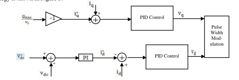
When a limit value of reactive power is reached, the control strategy of STATCOM is set up. Its reference value is determined by the ratio between the grid voltage and maximum of reactive power as . The control strategy is shown in Figure 5.
Fig. 5 Control strategy of STATCOM
III.
SIMULATION
RESULTS
The system under study is given in Figure 2. In this study, the simulations were conducted using MAT-LAB/SIMULINK software. In this section the dynamic response of 1.5MW DFIG based WT is simulated for a
PID Control
Pulse Width Mod-ulation
three phase symmetrical voltage dips, in which the grid voltage in three phases drops to 0.2pu (20% of its rated value) at t=0.9s and lasts for 300ms. Simulation parameters of the DFIG system are presented in Table I.
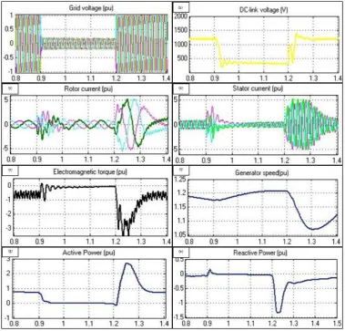
In this paper, two distinct cases are investigated and compared. In the first case, symmetrical grid voltage dips occurs under the conventional vector control of DFIG, simulation results shown in Figure 6. The second case the proposed LVRT strategy is applied (Figure 7).
TABLE I.
Simulation Parametres of Dfig System
Parameters Values
Rated power Power coefficient
Rated voltage Rated frequency (F) Stator resistance (Rs) Rotor resistance (Rr) The stator leakage inductance (Lls)
Rotor leakage inductance (Llr) Stator and rotor mutual inductance (Lm)
Number of pole pairs (p)
1.5MW 0.9 575V 50 Hz 0.00706 pu
0.005 pu 3.07 pu 3.056 pu
2.9 pu 6
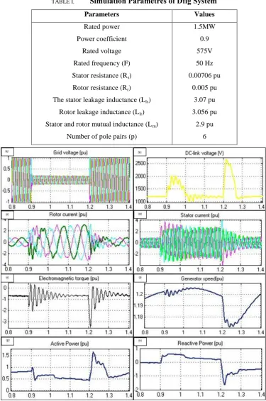
Figure 6 illustrates: (a) The grid voltage, (b) The DC-link voltage, (c) The rotor current, (d) The stator
current, (e) The electromagnetic torque, (f) The generator speed, (g) The active power and (h) The
reactive power. As can be seen from Figure 6, during the grid voltage dips and without any protective
measures, stator and rotor currents can be increased to 3 times the rated values, which can produce a
great harm to the RSC. Moreover, the electromagnetic torque has amplitude of more than 2 times its
nominal value and significant fluctuations, which will have an impact on drivetrain system and
me-chanical components of WT, as seen in Figure 6 f) the generator speed presents fluctuations. Active
and reactive powers are not stables, which has a negative impact on the weak power grid. The DC bus
voltage increased up to 2200V. Therefore, the GSC loses control and cannot be timely feed current to
the grid. This will seriously jeopardize the security and stability of the DC link operation.
to assist in keeping the grid voltage stable. After the voltage recovery, the Crowbar circuit is deactivated and the STATCOM is still activated and proving reactive power until the transients after fault are cleared.
IV.
CONCLUSION
This paper presents a LVRT strategy of DFIG based wind power generation system using STATCOM and Crow-bar circuit. When symmetrical grid voltage fault occurs, the proposed strategy: (i) efficiently suppress the rotor over-current and DC-link overvoltage, which protects the DFIG converter. (ii) Makes the DFIG system provides reactive power to the grid during voltage dips, facilitating DFIG to support the stability of the grid voltage. (iii) Can reduce the oscillation of electromagnetic torque which is helpful for the operation of the DFIG system. (iv) Contributes to improving the quality of the output power.
REFERENCES
[1] Yu Zou, Malik E. Elbuluk, Senior Member, IEEE, and Yilmaz Sozer, Member, IEEE: “Simulation Comparisons and Implementation of Induction Generator Wind Power Systems”. IEEE TRANSACTIONS ON INDUSTRY APPLICATIONS, VOL. 49, NO.3, MAY/JUNE 2013.
[2] Norouzi, A.H.; Sharaf, A.M.; , "Two control schemes to enhance the dynamic performance of the STATCOM and SSSC," Power Delivery, IEEE Transactions on , vol.20, no.1, pp. 435- 442, Jan 2005. [3] D. Xiang, L. Ran, P. Tavner, and S. Yang: 'Control of a doubly fed induction generator in a wind turbine
during grid fault ride-through", IEEE Trans. Energy Convers'. vol. 21, no. 3, pp. 652662, Sep. 2006. [4] Xiang Dawei, Ran Li, Tavner P J, et al. “Control of a Doubly Fed Induction Generator in a Wind Turbine
during Grid Fault Ride-Through”//Proceedings of IEEE Power Engineering Society General Meeting, Jun 18-22, 2006, Montreal, Canada.
[5] J. Lopez, P. Sanchis, X. Roboam, and L. Marroyo, “Dynamic behavior of the doubly fed induction generator during three-phase voltage dips”, IEEE Trans. Energy Convers., vol. 22, no. 3, pp. 709–717, Sep. 2007.
[6] C. Abbey; G. Joos: “Effect of low voltage ride through (LVRT) characteristic on voltage stability”. Power Engineering Society General Meeting, 2005. IEEE, pp. 1901- 1907 Vol. 2, 12-16 June 2005.
[7] P. Flannery and G. Venkataramanan, ”Evaluation of voltage sag ridethrough of a doubly fed induction generator WT with series grid side converter”, in Proc. 38th IEEE Power Electronics Specialists Conferences, Orlando, FL, USA, pp. 1839- 1845, 17-21 June 2007.
[8] Rahimi M, Parniani M., ”Efficient control scheme of WTs with doubly fed induction generators for low voltage ride-through capability enhancement”, IET Renew Power Gener 2010;4:24252.
[9] Iov F, Hansen A, Sorensen P, et al. “Mapping of grid faults and grid codes”. RISØ Report, 2007.
[10] Hua Geng, Member, IEEE, Cong Liu, and Geng Yang, Senior Member, IEEE,”LVRT Capability of DFIG-Based WECS Under Asymmetrical Grid Fault Condition”, IEEE TRANSACTIONS ON INDUSTRIAL ELECTRONICS, VOL. 60, NO. 6, JUNE 2013
[12] Holdsworth, L., Wu, X.G., Ekanayake, J.B. and Jenkins, N.: „Comparison of fixed-speed and doubly-fed induction generator wind turbines during power system disturbances‟, IEE Proc. C - Gener. Transm. Distrib., vol. 150, no. 3, pp. 343-352, July 2003.
[13] Dragan Jovcic, ”Phase locked loop system for FACTS[J]”.IEEE Trans on Power Systems,2003,18(3):1116-1122.