Article
1
Cogging torque reduction based on a new pre-slot
2
technique for a small wind generator
3
Miguel García-Gracia 1*, Ángel Jiménez Romero 1, Jorge Herrero Ciudad2 and Susana Martín
4
Arroyo1
5
1 Dpto. Ingeniería Eléctrica, Universidad de Zaragoza; [email protected]
6
2 For Optimal Renewable Energy Systems, S.L. (4fores); [email protected]
7
* Correspondence: [email protected]; Tel.: +34-976-761923
8
9
Abstract: Cogging torque is a pulsating, parasitic and undesired torque ripple intrinsic of the
10
design of a permanent magnet synchronous generator (PMSG), which should be minimized due to
11
its adverse effects: vibration and noise. In addition, as aerodynamic power is low during start-up at
12
low wind speeds in small wind energy systems, the cogging torque must be as low as possible to
13
achieve a low cut-in speed. A novel mitigation technique using compound pre-slotting, based on a
14
combination of magnetic and non-magnetic materials, is investigated. The finite element technique
15
is used to calculate the cogging torque of a real PMSG design for a small wind turbine, with and
16
without using compound pre-slotting. The results show that cogging torque can be reduced by a
17
factor of 48% with this technique, while avoiding the main drawback of the conventional
18
pre-slotting technique: the reduction of induced voltage due to leakage flux between stator teeth.
19
Furthermore, through a combination of pre-slotting and other cogging torque optimization
20
techniques, 84%, cogging torque can be eliminated for a given design.
21
22
Keywords: cogging torque; permanent magnet synchronous generator; small wind turbines; finite
23
element method; renewable energy, energy conversion.
24
25
1. Introduction
26
Increasing interest in the efficiency of electric machinery and reducing maintenance costs is
27
making the use of permanent magnet synchronous generators (PMSGs) more common. PMSGs
28
combine high efficiency with low maintenance and a high power density [1], factors that make them
29
extremely attractive for use in renewable energy applications, such as wind [2], wave power [3] and
30
tidal power [4], or electrical mobility applications [5] and, in general, in uses where they must act as
31
a motor or generator. Furthermore, in renewable energy applications, PMSGs allow direct-drive
32
configurations, making the use of gearbox unnecessary or reducing the number of gearbox stages,
33
which decreases the overall generator volume and improves its efficiency [6].
34
However, machines based on permanent magnets (PMs) also have some drawbacks, and the
35
cogging torque is one of the main ones. The magnetic interaction between the flux generated by the
36
rotor PMs and the stator geometry results in a pulsating torque called cogging torque, which,
37
depending on the PM machine design, can cause an undesired ripple in both the machine’s induced
38
voltage (EMF) and its mechanical torque [7,8]. Other problems with PMSGs are the vibrations and
39
noise they make. Since this type of machine has high magnetic flux density values in the air gap, the
40
electromagnetic forces between the PMs and the stator teeth are high [9]. These electromagnetic
41
forces are divided into two components, one radial and the other tangential. The tangential
42
component of the electromagnetic force contributes to the torque in the stator teeth, while the radial
43
component causes vibrations and even deformations in the machine [10]. These radial forces act on
44
the stator producing vibrations and noise, especially when their frequency coincides with the
45
natural frequency of the machine’s mechanical structure [11].
46
The cogging torque is especially important in wind energy applications as it establishes in which
47
conditions the system will begin generating. The mechanical torque captured by the generation
48
system must be larger than the cogging torque starting the rotation, which is why achieving a
49
reduced cogging torque is one of the objectives for this type of machine.
50
There are several methods to reduce cogging torque in the PMSG design phase. The most used
51
is skewing, which consists of preventing the stator teeth and the magnets from becoming aligned by
52
either turning the stator teeth [6, 12] or the rotor’s permanent magnets [1, 2, 13]. The required skew
53
angle to largely cancel out the effect of the interactions between the PMs and the slots depends on
54
how many slots and poles the machine has. Other methods study the use of notches in stator teeth
55
[7, 14]. These notches produce the same effect in the magnetic interaction as the slots and increase
56
the effective number of slots, which impacts on the cogging torque as it depends on how many poles
57
and slots the machine has. Therefore, this method’s effectiveness is conditioned by the number of
58
poles and slots selected in the design.
59
A study is presented in [15, 16] in which slot openings in one half of the stator shift in one
60
direction with respect to the tooth and the other half shift in the other direction. This means the
61
cogging torque waveform moves in opposite directions in each machine half and the cogging caused
62
by each machine half may be cancelled out depending on the shifted angle. Other studies focus on
63
the shape of PM edges, concluding that their size can be reduced on the magnet sides to lessen air
64
gap reluctance variation, which reduces the magnetic energy variation in the machine and,
65
therefore, mitigates the cogging torque [17, 18].
66
Several authors have conducted studies of PMSG with closed slots and their effects. Leakage
67
fluxes caused as a result of closing stator slots are analyzed in [4], concluding that the size of PMs
68
should be increased to compensate flux loss through closed slots. The increase in iron losses caused
69
by tooth-tip saturation, distortion in the induced voltage this saturation causes and how the use of
70
closed slots influences this are studied in [19 and 20]. The study by [21] focuses on average torque
71
and its ripple in machines with closed slots for several stator types.
72
Unlike the above-mentioned methods, which focus on minimizing the cogging torque in the
73
machine design stage, this article proposes a cogging torque reduction method that is easy to
74
implement without the need for any changes to the original design of the machine, a 6.3-kW
75
generator for a small wind turbine. The suggested solution comprises sliding a metal part (pre-slot)
76
into the slots after completing the machine winding. This technique minimizes slot openings so that
77
induced voltage remains unaltered and the mounting of machine windings is not hampered. The
78
results of the proposed method are analyzed using FEMM 2D finite element software on an original
79
PMSG design and compared with the results obtained experimentally. Additionally, constructive
80
improvements are suggested to reduce cogging torque. Finally, the article shows how the proposed
81
technique can also be combined with the skewing technique, thus significantly reducing the cogging
82
torque to 0.03 Nm in the ideal case and 0.51 Nm when imperfections in the manufacturing process
83
2. Machine type and main parameters
85
The machine involved in this study is a 6.3 kW PMSG with an interior rotor and
86
surface-mounted magnets comprising 36 slots and 20 poles. Figure 1(a) is a cross section of the
87
generator showing the slots forming the stator, the rotor in the internal part and the
88
surface-mounted magnets above it in the central part. The details of the millimeter measurements of
89
the machine’s slots and PMs are shown in Figure 2. The characteristic parameters of the studied
90
PMSG are shown in Table 1.
91
The analysis of the PMSG and the cogging torque reduction methods proposed in this study has
92
been performed using FEMM 2D finite element software. To validate the FEMM model used in the
93
cogging torque reduction analysis a comparison will be made with the experimental values of the
94
original machine.
95
96
(a) (b)
Figure 1. Cross section area of the PMSG: (a) Original model; (b) Model with centered holes.
97
98
Figure 2. Slot and magnet dimensions (mm).
99
Parameter Value
Phase 3
Pole number 20 Slot number 36 Rated speed 232 rpm Rated power 6300 W Rated voltage 256.4 V
Air gap 1 mm
Thickness of PM 3 mm Air gap diameter 188 mm
Material of steel M330-50A Material of PM NdFeB
3. Cogging torque
101
Cogging torque is a parasitic torque resulting from interactions between the rotor’s permanent
102
magnets and the stator slots. Air gap reluctance differs depending on the rotor’s angular position to
103
the slots. Rotor magnets tend to align with the stator in the position in whichair gap permeance is
104
larger [22], so when they are shifted from this position during rotation, they generate a torque, the
105
cogging torque.
106
Electromagnetic torque can be obtained from the variation in the total energy of the magnetic
107
field compared with the angular position of the rotor θ when excitation current is constant [14]
108
= − (1)
The total energy stored in the magnetic field or coenergy Wc in a PMSG is given by [7]
109
=1
2 +
1
2( + ) ∅ + ∅ (2)
where L is the inductance of the windings, i the excitation current, R and Rm are, respectively, the
110
reluctances viewed by the magnetomotive force and by the magnetic field, Фm the flux due to the
111
magnets crossing the air gap, and N the number of winding turns.
112
Therefore, substituting in (2) results in
113
=1
2 −
1
2 ∅ +
∅ (3)
The second term of (3) corresponds to magnet reluctance torque and it is known as cogging
114
torque [17], Tcog.
115
= −1
2∅ (4)
As observed in (4), cogging torque is independent of the current and corresponds to the result
116
of analyzing (3) when the machine is in open circuit. Cogging torque depends on magnetic flux and
117
on the rate of change of air-gap reluctance. From (4), to minimize Tcog, reluctance R should be
118
independent of the rotor position. Therefore, a very low cogging torque design requires an almost
119
constant value of R for any rotor position.
120
4. Cogging torque measurement
123
Cogging torque is calculated in FEMM for every angular rotor position, making the machine
124
operate off-load. The torque is calculated by integrating the Maxwell stress tensor throughout the air
125
gap
126
=
μ
(5)
where L is the rotor depth, g is the air gap length, Bn the normal flux density, Bt the tangential flux
127
density and r the radius from the center of the rotor to the center of the air gap [7].
128
Compared with the results obtained when the calculation is based on the magnetic energy
129
variation with respect to the angular rotor position given by (1), in [18] it is shown that both methods
130
obtain almost identical results.
131
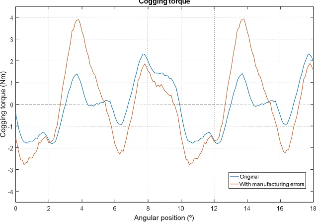
The simulation in FEMM of the PMSG in Figure 1 (a) obtained the cogging torque shown in
132
Figure 3 (“original” curve), whose maximum value is 2.32 Nm, while the experimental results of the
133
machine show maximum values of 3.70 Nm. The main reason for this deviation from experimental
134
values is due to component manufacturing tolerance. Consequently, if a tolerance of ± 0.1 mm is
135
included in the 20 PMs of the PMSG model and this error is distributed randomly at the height of the
136
PMs, the result shown in Figure 3 (curve “with manufacturing errors”) is obtained. Having magnets
137
that are not the same impacts the cogging torque significantly, mainly because differently sized PMs
138
cause higher magnetic flux variations in the air gap. The maximum cogging torque value obtained in
139
the simulation is 3.90 Nm (Figure 3). This value is slightly higher than the experimental PMSG
140
results, making it possible to validate the developed FEMM model with respect to the cogging
141
torque analysis.
142
143
Figure 3. Simulation results of cogging torque of the original model considering manufacturing errors.
144
145
146
147
C
o
g
g
in
g
t
o
rq
u
e
(
N
m
5. Cogging torque reduction methods
148
5.1.Pre-slot method
149
The main objective is to reduce the cogging torque without affecting the machine’s construction
150
characteristics and, therefore, without making any changes in the generator’s geometry.
151
A closed-slot stator topology reduces reluctance variation in the air gap and, therefore, the
152
machine’s maximum cogging torque value. Furthermore, the minimum dimensions of PMSG slot
153
openings are conditioned by winding mounting factors. Their minimum size depends on the cross
154
section of the winding conductors so that they can be inserted in the slot.
155
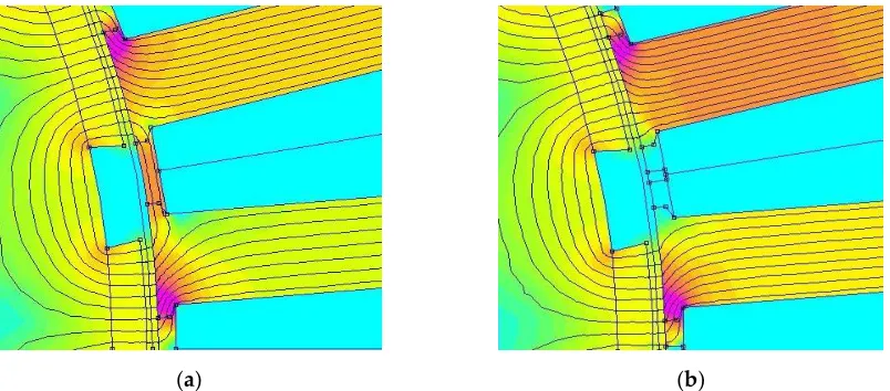
Furthermore, the slot closing method has the drawback of generating a leakage flux through the
156
slots due to the high permeability of the magnetic core connecting the teeth, Figure 4 (a). These
157
leakages reduce the flux linked by the machine windings, thus producing a drop in induced voltage.
158
This drop in induced voltage can be seen in Figure 5, showing the induced voltage of the PMSG with
159
open slots (the “original” curve) and with closed slots. The effective induced voltage value is 256.4 V
160
in the original generator model with open slots, and it decreases to 221.6 V when the slots are closed.
161
(a) (b)
Figure 4. Magnetic field lines (θ=0°): (a) Model with closed slots; (b) Model with pre-slots.
162
163
Figure 5. Effect of closed slots in back electromotive force (EMF).
164
P
h
a
s
e
b
a
c
k
-E
M
F
(
V
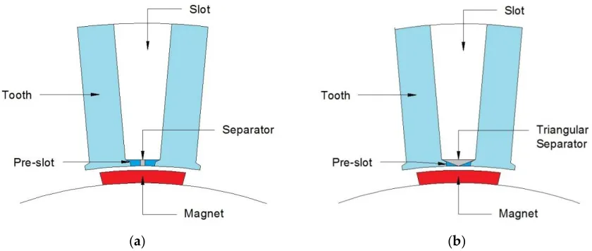
To avoid the above-mentioned drawbacks, the proposed cogging torque reduction method
165
consists of closing the slots by sliding in a pre-slot part made of the same ferromagnetic material as
166
the stator, as observed in Figure 6. The pre-slot is placed between the teeth longitudinally after
167
machine winding; this does not alter the winding or the slot fill factor. Figure 6 (a) provides details of
168
the space between two of the machine’s stator teeth showing where the ferromagnetic part is slid
169
into the start of each slot. The pre-slot considered in this study is 1.5 mm high; its dimensions are
170
adjusted to the available space to render changing the machine winding unnecessary.
171
A material separator with low magnetic permeability (aluminum or similar) and a width of
172
1 mm, the same distance as the machine’s air gap, is in the central part of the pre-slot. The purpose of
173
the central separator is to prevent the above-mentioned flux leakage linked by the windings. As this
174
is a non-magnetic separator, it prevents the pre-slot from closing the magnetic field lines and,
175
therefore, preventing flux from circulating between two consecutive PMs.
176
(a) (b)
Figure 6. Proposed cogging-torque reduction method: (a) Pre-slot with separator; (b) Pre-slot with triangular
177
separator.
178
In accordance with the developed FEMM model, inserting pre-slots with a separator manages
179
to reduce the maximum cogging torque value by 37.9% compared with the original PMSG, as
180
observed in the results shown in the graph in Figure 7, but it does not decrease induced voltage as
181
using the separator reduces leakages.
182
This cogging torque reduction can be improved by considering other alternative geometrical
183
pre-slot configurations. A triangular separator, as shown in Figure 6 (b), can lessen the magnetic
184
energy variation caused in the original teeth edges or in pre-slot separators, which decreases the
185
machine’s cogging torque.
186
Pre-slot geometry with a triangular separator prevents leakage flux through it, as occurs with
187
the central separator model, thus preventing the undesired decrease in induced voltage and in
188
linked flux through machine windings. Similarly, it produces a higher reduction in maximum
189
cogging torque, as shown in the graph in Figure 8, decreasing the cogging torque generated by over
190
192
Figure 7. Comparison of cogging torque reduction with pre-slot method.
193
194
Figure 8. Comparison of cogging torque reduction with the triangular pre-slot method.
195
An analysis of induced voltage harmonics was conducted to confirm that the installation of the
196
proposed pre-slot system to reduce cogging torque does not affect the machine’s technical
197
characteristics. The PMSG is designed for small wind-power applications and, therefore, if an
198
uncontrolled rectifier is used, the harmonics level is of no importance. However, if the connection is
199
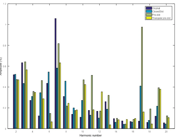
via a full converter, the opposite is the case. Figure 9 shows the frequency spectrum of the first 20
200
harmonics of each of the waves and the harmonic distortion rate (THD) for each model; therefore,
201
the analysis was conducted from the fundamental frequency of 38.67 Hz to the twentieth harmonic
202
(773.4 Hz).
203
C
o
g
g
in
g
t
o
rq
u
e
(
N
m
Table 2 shows how the THD values obtained remain low and similar across all cases and never
204
exceed 2%. The pre-slot solution with a triangular separator presents the least harmonic distortion of
205
the considered models; it is very similar to the closed-slot model and improves the original
206
configuration.
207
208
Figure 9. Harmonic spectrum for the proposed reduction method.
209
Table 2. THD of the different models.
210
Model THD (%)
Original design 1.54 Design with closed slot 1.39 Design with pre-slot 1.88 Design with triangular pre-slot 1.33
211
5.2.Manufacturing aspects to reduce the cogging torque
212
Any change in the magnetic circuit alters its reluctance and, therefore, in accordance with (4), it
213
affects the cogging torque and must be considered to reduce it. Consequently, it was found that the
214
holes for correctly aligning the rotor sheet metal with screws in the original design significantly
215
influence the machine’s cogging torque, depending on their position with respect to the PMs, Figure
216
1(b).
217
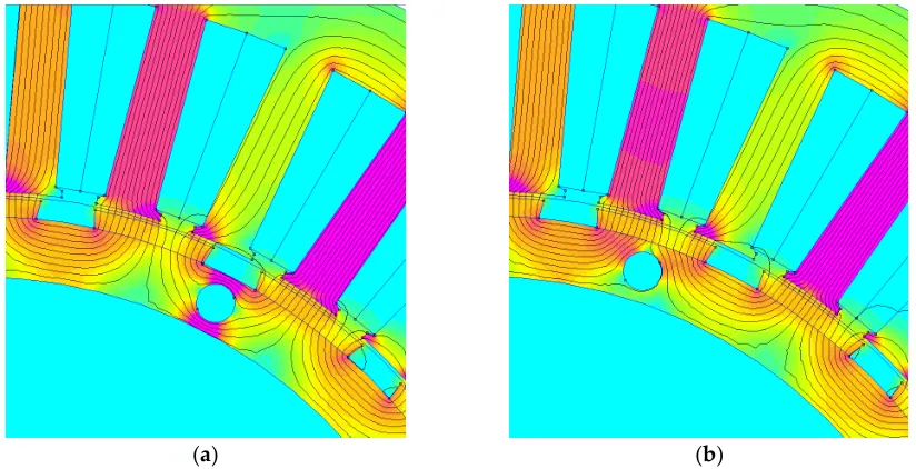
The impact of these holes on the cogging torque was analyzed for their different positions with
218
respect to the PMs. The conclusion is that the optimal position, which minimizes cogging torque, is a
219
centered position with respect to the magnets. Figure 10 (b) shows the case in which the rotor hole is
220
centered with respect to the PMs. In this situation, the holes have virtually no influence on magnetic
221
field lines linking one magnet with another. In contrast, when the hole is decentered, Figure 10 (a),
222
the effect is a smaller effective area in the rotor through which the field lines circulate. Therefore,
223
reluctance increases with respect to the case shown in Figure 10 (b) (centered hole) and the magnetic
224
energy in the rotor decreases as observed in Figure 11.
225
A
m
p
lit
u
d
e
(
%
(a) (b)
Figure 10. Magnetic field distribution (θ=0°): (a) Original model, without centered holes; (b) Model with
226
centered holes.
227
228
Figure 11. Magnetic energy in the rotor.
229
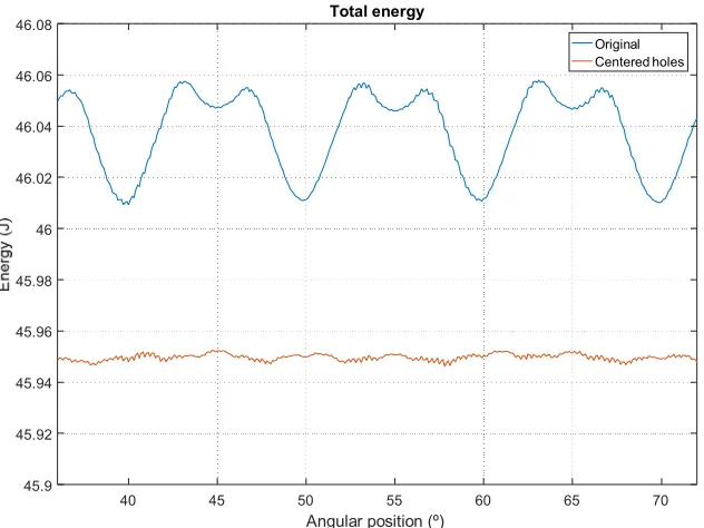
Figure 12 shows the magnetic energy stored in the machine with respect to the rotor during
230
electrical 360° (mechanical 36°) for both PMSG models. If the hole is decentered, energy minimums
231
occur when the hole is aligned with a stator tooth. In this position, the flux between two adjacent
232
magnets would be the maximum if there was no hole. Consequently, as observed in Figure 12, and
233
given that the teeth are distributed every mechanical 10° along the stator, the energy minimum
234
occurs with this frequency.
235
E
n
e
rg
y
(
J
236
Figure 12. Total magnetic energy.
237
Figure 13 compares the cogging torque for both PMSGs, resulting in a higher value when the
238
hole is decentered given that more magnetic energy variations occur, as presented in Figure 12. The
239
cogging torque of the model with decentered holes is 2.32 Nm, while this value does not exceed
240
0.86 Nm when the holes are centered. Figure 13 also shows that the presence of decentered holes
241
even produces a change in the cogging torque wave period.
242
243
Figure 13. Cogging torque of the original PMSG and model with centered holes.
244
245
246
247
40 45 50 55 60 65 70
Angular position (º) 45.9
45.92 45.94 45.96 45.98 46 46.02 46.04 46.06
46.08 Total energy
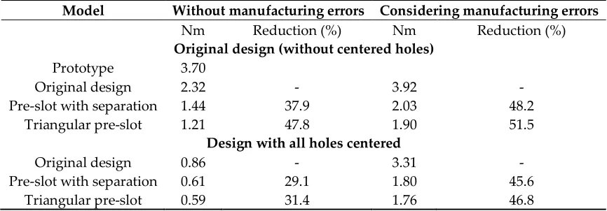
5.3.Comparative results
248
Table 3 compares the maximum cogging torque values obtained with the original design with
249
the two proposed pre-slot configurations and shows the reduction percentage with respect to the
250
original design. The results of the different models are shown in the ideal case (with no
251
manufacturing errors) and considering manufacturing errors in the magnets.
252
253
Table 3. Comparison of the maximum cogging torque values obtained for the prototype and the different
254
models considered in the study.
255
Model Without manufacturing errors Considering manufacturing errors
Nm Reduction (%) Nm Reduction (%)
Original design (without centered holes)
Prototype 3.70
Original design 2.32 - 3.92 -
Pre-slot with separation 1.44 37.9 2.03 48.2
Triangular pre-slot 1.21 47.8 1.90 51.5
Design with all holes centered
Original design 0.86 - 3.31 -
Pre-slot with separation 0.61 29.1 1.80 45.6
Triangular pre-slot 0.59 31.4 1.76 46.8
256
Finally, the proposed pre-slot method was compared with the skewing technique and the
257
combination of both is considered. The technique of fractional skewing in the rotor [23] comprises
258
dividing the rotor and turning one division away from another for half the cogging torque period.
259
Four divisions have been considered in this analysis, as observed in Figure 14. Therefore,
260
considering that the cogging torque period is mechanical 2, the shift of one division with respect to
261
another is half of this period, which equals 1. As observed in Table 4, concerning the model with
262
centered holes and in the ideal case of having no manufacturing errors, applying this combined
263
technique manages to reduce the cogging torque to a peak value of 0.03 Nm or to 0.51 Nm if
264
manufacturing errors are considered. In either of the two cases, the cogging torque reduction is very
265
significant.
266
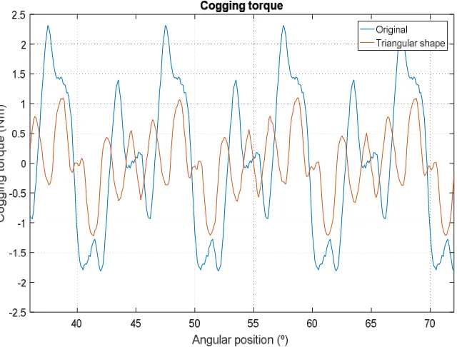
Figure 15 shows the cogging torque waveform obtained for the PMSG with centered holes.
267
Because of the reluctance periodicity, the cogging torque is a periodic waveform with a frequency
268
given by:
269
= ∙ ,
360° = 696
(6)
where is the mechanical speed (1392°/s), LCM the least common multiple of the number of slots
270
(Nslots=36) and the number of poles (Npoles=20). The results in Figure 15 show the decrease in the
271
cogging torque with the pre-slot triangular method and that this improvement is even better when
272
combining this pre-slot installation technique with fractional skewing in the rotor, up to 84% less in
273
275
Figure 14. Fractional skewing in the rotor.
276
Table 4. Comparison of the maximum cogging torque values of PMSG with centered holes and the different
277
models considering skewing.
278
Model Without manufacturing
errors
Considering manufacturing errors Nm Reduction (%) Nm Reduction (%)
Design with centered holes 0.86 - 3.31 -
Design with centered holes + Triangular
pre-slot 0.59 31.4 1.76 46.8
Design with centered holes + Skewing 0.31 64.0 1.34 59.5 Design with centered holes + Triangular
pre-slot + Skewing 0.03 96.5 0.51 84.6
279
Figure 15. Cogging torque of the centered holes PMSG model, triangular pre-slot model and triangular pre-slot
280
model with skewing (with manufacturing errors).
281
282
283
284
C
o
g
g
in
g
t
o
rq
u
e
(
N
m
6. Conclusions
285
This article presents a new cogging torque reduction technique that does not require changes to
286
the machine’s main geometry. It proposes placing pre-slots in the initial part of the stator slots. These
287
pre-slots are made of the same ferromagnetic material as the stator, with a non-magnetic central
288
separator (in two halves). The pre-slots are slid longitudinally between the slots after completing
289
machine winding and, therefore, without altering the PMSG’s fill factor.
290
Introducing a central part of non-magnetic material prevents leakage flux between the
291
machine’s teeth and also stops its induced voltage from reducing significantly with respect to the
292
configuration without pre-slots.
293
The proposed method manages to reduce cogging torque in PMSGs with surface-mounted
294
magnets by up to 47.8%. Additionally, the article analyzes how changing the magnetic circuits for
295
construction reasons can affect the cogging torque, which can easily be optimized. The pre-slot
296
technique is also compatible with other cogging torque reduction techniques, such as skewing.
297
When the above-mentioned methods are combined, cogging torque is reduced by 84.6% considering
298
manufacturing errors.
299
300
Author Contributions: Miguel García-Gracia and Ángel Jiménez Romero performed the simulations and wrote
301
the paper. 4fores contributed with the prototype and valuable comments and corrections. All authors discussed
302
the results and commented on the manuscript at all stages.
303
Funding: This research was funded by “Ministerio de Economía, Industria y Competitividad (Plan Estatal de
304
Investigación Científica y Técnica y de Innovación 2013-2016)” and “Fondo Europeo de Desarrollo Regional FEDER”,
305
grant number RTC-2016-5234-3, in the frame of the Project MHiRED “Nuevas tecnologías para minirredes híbridas
306
eólica-fotovoltaica gestionadas con almacenamiento en conexión a red y con apoyo síncrono en funcionamiento en isla”.
307
Acknowledgments: The authors wish to thank 4fores for granting their permission to publish some data
308
presented in this article. Furthermore, the technical support from the Research Group on Renewable Energy
309
Integration of the University of Zaragoza (funded by the Gobierno de Aragón) is also gratefully acknowledged.
310
Conflicts of Interest: The authors declare no conflict of interest.
311
312
References
313
1. Fei, W.; Zhu, Z. Q. Comparison of Cogging Torque Reduction in Permanent Magnet Brushless Machines
314
by Conventional and Herringbone Skewing Techniques. IEEE Trans. Energy Convers. 2013, 28 (3), 664–674.
315
2. Ose-zala, B.; Pugachov, V. Methods to Reduce Cogging Torque of Permanent Magnet Synchronous
316
Generator Used In Wind Power Plants. Elektron. ir Elektrotechnika 2017, 23 (1), 43–48.
317
3. Leijon, J.; Sjölund, J.; Ekergård, B.; Boström, C.; Eriksson, S.; Temiz, I.; Leijon, M. Study of an Altered
318
Magnetic Circuit of a Permanent Magnet Linear Generator for Wave Power. Energies 2018, 11 (1), 1–13.
319
4. Lejerskog, E.; Leijon, M. Detailed Study of Closed Stator Slots for a Direct-Driven Synchronous Permanent
320
Magnet Linear Wave Energy Converter. Machines 2014, 2 (1), 73–86.
321
5. Raihan, M. A. H.; Smith, K. J.; Almoraya, A. A.; Khan, F. Interior Permanent Magnet Synchronous Machine
322
( IPMSM ) Design for Environment Friendly Hybrid Electric Vehicle ( HEV ) Applications. In Humanitarian
323
6. Öztürk, N.; Dalcali, A.; Çelik, E.; Sakar, S. Cogging Torque Reduction by Optimal Design of PM
325
Synchronous Generator for Wind Turbines. Int. J. Hydrogen Energy 2017, 42 (28), 17593–17600.
326
7. Ozoglu, Y. New Stator Tooth for Reducing Torque Ripple in Outer Rotor Permanent Magnet Machine.
327
Adv. Electr. Comput. Eng. 2016, 16 (3), 49–56.
328
8. Liu, C.; Lu, J.; Wang, Y.; Lei, G.; Zhu, J.; Guo, Y. Techniques for Reduction of the Cogging Torque in Claw
329
Pole Machines with SMC Cores. Energies 2017, 10 (10), 1–17.
330
9. Ito, T.; Akatsu, K. Electromagnetic Force Acquisition Distributed in Electric Motor to Reduce Vibration.
331
IEEE Trans. Ind. Appl. 2017, 53 (2), 1001–1008.
332
10. Chen, Y. S.; Zhu, Z. Q.; Howe, D. Vibration of PM Brushless Machines Having a Fractional Number of
333
Slots per Pole. IEEE Trans. Magn. 2006, 42 (10), 3395–3397.
334
11. Min, S. G.; Bramerdorfer, G.; Sarlioglu, B. Analytical Modeling and Optimization for Electromagnetic
335
Performances of Fractional-Slot PM Brushless Machines. IEEE Trans. Ind. Electron. 2017, 65 (5), 4017–4027.
336
12. Tseng, W.; Chen, W. Design Parameters Optimization of a Permanent Magnet Synchronous Wind
337
Generator. 19th Int. Conf. Electr. Mach. Syst. 2016.
338
13. Levin, N.; Orlova, S.; Pugachov, V.; Ose-Zala, B.; Jakobsons, E. Methods to Reduce the Cogging Torque in
339
Permanent Magnet Synchronous Machines. Electron. Electr. Eng. 2013, 19 (1), 23–26.
340
14. Ma, G.; Li, G.; Zhou, R.; Guo, X.; Ju, L.; Xie, F. Effect of Stator and Rotor Notches on Cogging Torque of
341
Permanent Magnet Synchronous Motor. IEEE Trans. Ind. Appl. 2017, No. 1.
342
15. Liu, T.; Huang, S.; Gao, J.; Lu, K. Cogging Torque Reduction by Slot-Opening Shift for Permanent Magnet
343
Machines. IEEE Trans. Magn. 2013, 49 (7), 4028–4031.
344
16. Dajaku, G.; Gerling, D. New Methods for Reducing the Cogging Torque and Torque Ripples of PMSM.
345
2014 4th Int. Electr. Drives Prod. Conf. EDPC 2014 - Proc. 2014.
346
17. Hsiao, C.; Yeh, S; Hwang, J. Permanent Magnet Structure Optimization for Cogging Torque Reduction of
347
Outer Rotor Type Radial Flux Permanent Magnet Generator.A novel cogging torque simulation method
348
for permanent-magnet synchronous machines .Energies 2011, 4, 2166-2179.
349
18. Imamori, S.; Ohguchi, H.; Shuto, M.; Toba, A. Relation between Magnetic Properties of Stator Core and
350
Cogging Torque in 8-Pole 12-Slot SPM Synchronous Motors. IEEJ J. Ind. Appl. 2015, 4 (6), 696–702.
351
19. Wu, D.; Zhu, Z. Q.; Chu, W. Q. Iron Loss in Surface-Mounted PM Machines Considering Tooth-Tip Local
352
Magnetic Saturation. 2016 IEEE Veh. Power Propuls. Conf. VPPC 2016 - Proc. 2016, No. 2011.
353
20. Wu, D.; Zhu, Z. Q. On-Load Voltage Distortion in Fractional Slot Surface-Mounted Permanent Magnet
354
Machines Considering Local Magnetic Saturation. IEEE Trans. Magn. 2015, 51 (8).
355
21. Li, Y. X.; Li, G. J. Influence of Stator Topologies on Average Torque and Torque Ripple of Fractional-Slot
356
22. Todorov, G.; Stoev, B.; Savov, G.; Kyuchukov, P. Effects of Cogging Torque Reduction Techniques
358
Applied to Surface Mounted PMSMs with Distributed Windings. 2017 15th Int. Conf. Electr. Mach. Drives
359
Power Syst. ELMA 2017 - Proc. 2017, 17–21.
360
23. Galfarsoro, U.; Parra, J.; McCloskey, A.; Zarate, S.; Hernandez, X. Analysis of Vibration Induced by
361
Cogging Torque in Permanent-Magnet Synchronous Motors. Proc. 2017 IEEE Int. Work. Electron. Control.
362
Meas. Signals their Appl. to Mechatronics, ECMSM 2017 2017.
363