The Interaction Vortex Flow Around Two Bluff Cylinders
Y. Yokoi1,a, and K. Hirao2
1National Defense Academy, Department of Mechanical Engineering, 1-10-20 Hashirimizu, Yokosuka 239-8686, Japan
2Japan Air Self-Defense Force, Gifu Base, Naka-kanyuumubanchi, Kakamigahara, Gifu 504-8701, Japan
Abstract. In this study, the interaction vortex flow features around a pair of parallel arranged bluff cylinders were observed by visualizing water flow experiment at the range of the gap ratio G/d=0~3. It was obtained that the result of established wind tunnel test and the result of this water tank test agreed about the characteristics of vortex shedding when varying the distance of circular cylinder gap. The flow pattern and vortex shedding frequency of another type bluff cylinder (triangular and square cylinder) were also investigated. As a result of the experiment, it was shown that the flow pattern of wake flow was divided into three kinds (coupled vortex streets, biased gap flow and single vortex street) regardless of the cylinder section shape and cylinder size. Then, the region of the appearance of flow pattern was shown about each case. In the case where two each other independent vortex streets were formed, three typical flow patterns of vortex formation (in-phase coupled vortex streets, out-of-phase coupled vortex streets and complication coupled vortex streets) were observed. It was known that three configuration of vortex formation appear intermittently and alternatively.
1 Introduction
If a bluff cylinder is placed into a flow, the Karman vortex street will occur behind the bluff cylinder. In the fluid engineering field, this is a phenomenon known well and is a very familiar phenomenon also in everyday life. By this Karman vortex, a flow causes oscillation and fluid force transmits it to the bluff cylinder. Then, the bluff cylinder may be excited by oscillation of the fluid. Such the phenomenon is called a flow induced vibration and is one of the very interesting phenomena in an engineering field. In the design of a structure, it is important to estimate oscillation produced according to the fluid force. Therefore, it is positioned as the important study theme in the engineering field. When an example is given as the structure placed into the flow, they are a high-rise building, the masts of a ship, multi-leg chimneys, power lines, the leg structures of an offshore oil field platform, the pipes of a heat exchange machine, etc. The fundamental shape of these structures and structural elements is a circular cylinder, a triangular cylinder, and a square cylinder. And they exist by plurality in many cases rather than existing independently. It is important in the engineering field to understand the fluctuation fluid force accompanied by mutual interference and the vortex flow of multi-bluff cylinders. And it is meaningful as basic data for systematic grasp of the flow induced vibration phenomenon.
In relation to the practical use problem of many fields, such as mechanical engineering, civil engineering, and
architectural engineering, there is much study on the vortex flow in the case of having arranged two circular cylinders in a flow. The examples of typical arrangement of two circular cylinders are tandem arrangement and parallel arrangement. Nevertheless, the report of research performed by parallel arrangement has few numbers compared with the report of research performed by tandem arrangement. Now, some examples are only seen [1-7]. The study using the two bluff cylinders from which study of the two bluff cylinders using a triangular cylinder or a square cylinder and cross-sectional shape differ is equal to there being almost nothing. Study of the flow around a pair of two bluff cylinders with cross-sectional shape other than a circular cylinder has the very high value as engineering underlying data. So, accumulation of data is demanded.
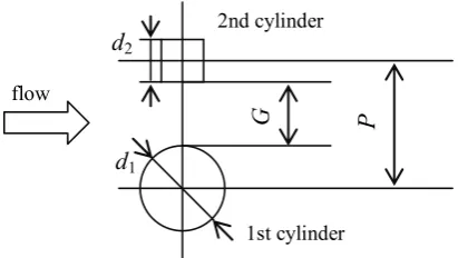
In this study, about the mutual interference vortex flow from two bluff cylinders arranged in parallel, the combination and the gap ratio of bluff cylinder were varied and the visualization experiment was performed. Here, the combination of two bluff cylinders is the same size, different size, and a different shape. The gap ratio is defined by G/d, G is the gap of two bluff cylinders and d is the projection width of the bluff cylinder. Investigation of the flow pattern of each gap ratio and the vortex shedding characteristic from each bluff cylinder were performed. In the combination of each two bluff cylinder, the ranges of the gap ratio which carries out mutual interference, fundamental flow patterns, and intermittent substitution of flow patterns were shown.
EPJ Web of Conferences DOI: 10.1051/
C
Owned by the authors, published by EDP Sciences, 2013 ,
epjconf 201/
01098 (2013)
45
34501098
This is an Open Access article distributed under the terms of the Creative Commons Attribution License 2 0 , which . permits unrestricted use, distributi and reproduction in any medium, provided the original work is properly cited.
Fig. 1. Aspect of a towing water tank.
Fig. 2. Aspect of a closed circuit water channel. Fig. 3. Coordinate system and definition of symbols.
d1
G P
flow
d2
1st cylinder 2nd cylinder
2 Experimental apparatus and Method
2.1 Outline of experimental apparatus
The experimental apparatus consists of a towing water tank, a closed circuit water channel, visualization equipment, and recording equipment. In the experiment, two kinds of water tank equipment were properly used according to the use. Observation of the flow pattern and measurement of the vortex shedding frequency were performed using the towing water tank. The check of a phenomenon and record photography which were obtained were performed using the closed circuit water channel. Figure 1 shows a cover shot of the towing water tank. The towing water tank consists of a main tank unit, a rail unit, a towing carriage and drive equipment. The length of the main tank unit is 10 m, the width is 0.8 m, the depth is 0.7 m and the both side walls are made from glass. So as not for the vibration when towing a carriage to propagate to the main tank unit, the main tank unit and rail unit become separate. The towing carriage which was put on the rail unit is operated by the drive equipment using two timing belts.
Figure 2 shows a cover shot of the closed circuit water channel. The closed circuit water channel is a vertical circulation type of 5.8 m in length, 1.2 m in width, and 2.5 m in height, and the volume of water is 4 m3 (4 tons). The water channel is consisted of water flow generation equipment (two sets of axial flow type pumps), rectification device, test section and 4 corner parts with
guide vanes. The test section is 2 m in length, 0.8 m in width, 0.4 m in depth, and the flume structure with the surface of the water. In the test section, the window made of the glass of 1.5 m in length and 0.4 m in width has been installed in the both sides wall and the bottom for the observation. The velocity distribution in the test section was plus-minus 1.5 % against main flow velocity 0.4 m/s from depth 50 - 350 mm and the test section center in the direction of width within the range of plus-minus 300 mm. There is a set of rail orbit on the flume flange and a carriage is set up.
Two sets of the halogen lights of 500 W were used as a visualization lighting installation. Two sets of halogen light are equipped on the carriage of towing water tank, and the test section of closed circuit water channel is equipped with two sets of halogen light. The recording equipment consists of a small 3CCD color video camera for industry, and a set of video recording playback equipment.
2.2 Test cylinders
The length of all the test cylinders used in the experiment is 600 mm. The cross-sectional shape of a test cylinder is three kinds, circular, a square, and an equilateral triangle. Cylinder size is four kinds and each diameter is 8, 16, 25
and 32 mm. Two tracer oozing ports (φ1 mm) are
2.3 Flow visualization method
The flow visualization was performed by the streak line method which used tracer ink. The tracer was made to ooze from the oozing port on the surface of cylinder in the case of circular cylinder and square cylinder. In the case of the right triangular cylinder, the small tube for tracer introduction was provided in the upstream side of the cylinder, and tracer oozing was performed from there. As for tracer ink, Rhodamine B was used in the experiment of frequency measurement, and the poster paint (turquoise and fluorescence pink) of two colors was used in record photography. The specific gravity of the tracer ink used here is adjusted so that it may become the same as surrounding fluid (water).
2.4 Experimental parameters
The main experimental parameters are given by the shape of cylinder, the size of cylinder, the combination of cylinder and the gap ratio G/d (the ratio of gap between cylinders G to the projection width of larger cylinder d). The shapes of each cylinder are circular, square, and equilateral triangle, and are five kinds (circular, flat face square, sharp square, flat face triangular and sharp triangular) including the case where direction is varied. About the size of the cylinder, they are a total of eight kinds. The number of circular cylinders is four (8, 16, 25, and 32 mm), that of square cylinders is three (9, 15, and 20 mm), and that of equilateral triangle cylinders is one (20 mm). The combinations of two bluff cylinders are three kinds, and are the same size (the projection width same in the same shape), different size (projection width which is different in the same shape), and a different shape. Here, the flow velocity which is easy to visualize the experimental flow velocity in each water tank was chosen. The towing speed (the relative flow velocity) at the towing water tank was 0.045 m/s, and the flow velocity in the test section at the closed circuit water channel was 0.085 m/s.
2.5 Experimental procedure
The experiment using the towing water tank was performed in the following procedures. Water is filled so that the water level of water tank may be set to 400 mm. The controller of towing drive is operated and the towing carriage velocity is set up. The cylinder setting interval (gap ratio, G/d) is determined and cylinders are installed on the towing carriage. Towing of carriage is performed after water fully suppressed. The tracer is made to ooze during towing of carriage under the water surface in the position of 150 mm. The aspects of the visualized flow are observed with a video camera, and it records on the videotapes. After towing, the carriage returns to the start position, changes a setup, and repeats operation.
The experiment using the closed circuit water channel was performed in the following procedures. Water is filled and prepared so that the water level of the test section of the water tank may be set to 400 mm. An operating condition is inputted into the operation operator
control panel of the closed circuit water channel, and the flow velocity of test section is set up. Cylinders are set up based on the gap ratio G/d. The tracer ink is oozed under the water surface in the position of 150 mm, and flow visualization is performed. The aspect of the visualized flow is observed with a video camera, and it records on video tape. The frequency of the vortex shedding from the cylinder was calculated from the number and measurement time of the vortex which passes through the observation point arbitrarily appointed about each cylinder. Here, the range of an observation position is cylinder behind from 1.5d to 3d approximately, and the separating shear layer discharged from the both sides of cylinder made it the position which can observe both.
In the coloring in the flow visualization of record photography, turquoise was used for the 1st cylinder and fluorescence pink was used for the 2nd cylinder. Moreover, in the coloring of 25 mm circular cylinder which can be oozed individual, turquoise was used for left-hand side and fluorescence pink was used for right-hand side.
3 Experimental results and discussion
3.1 In the case of same size cylinder
In order to verify the validity of this visualization measurement technique, the verification experiment was performed about the case of two circular cylinders arranged in parallel. The gap ratio G/d of parallel two circular cylinders was varied, and it compared with the previous experimental result [1, 2]. It is known that the Strouhal number in the vortex flow of the behind of parallel two circular cylinders will change with gap ratio G/d like the following description. Here, a Strouhal number is defined by St=fd/U (f is vortex shedding
frequency, d is cylinder projection width, and U is the
flow velocity). In the region of G/d>1, the value of the Strouhal number is not different from the value of an independent circular cylinder (single cylinder). In the region of 0.5<G/d<1, two values of Strouhal number exist. In the region of G/d<0.5, the value of Strouhal number turns into a value of the half of an independent circular cylinder. The present visualization experimental result which used the circular cylinder with a diameter of 16mm and a diameter of 25mm, and the previous wind tunnel experimental result are shown in figure 4. An abscissa is the gap ratio G/d and an ordinate is a Strouhal number St.
In this case, Reynolds number Re (= Ud/ν, ν are
Fig. 4. Strouhal number in terms of gap ratio G/d in the case of circular cylinder.
0 0.5 1 1.5 2 2.5 3
0 0.1 0.2 0.3 0.4
G/d
St
一 Spivack (1)
-- Bearman & Wadcock (2)
1st , 2nd 25mm-25mm ○ ●
16mm-16mm △ ▲
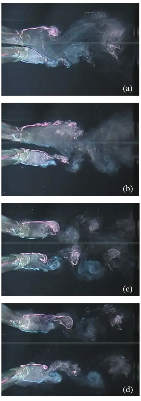
Fig. 5. Representative flow patterns, (a) Single vortex street G/d=0.2, (b) Biased gap flow G/d=0.6, (c) In-phase coupled vortex streets G/d=1.0, (d) Out-of-phase coupled vortex streets G/d=3.0
the flow pattern of two circular cylinders of parallel arrangement will change with gap ratio G/d. The flow patterns are divided roughly into the region which carries out mutual interference, and the region not influencing by gap ratio G/d=1. When the gap ratio G/d is G/d<1, the vortices discharged from two circular cylinders interfere mutually, and a wake vortex street is formed. When the gap ratio G/d is G/d>1, an alternate vortex street is formed in independent from two circular cylinders. Here, if its attention is paid to cylinder near wake, in the former region, it will be more divided into two regions by gap ratio G/d=0.5. When the gap ratio G/d is G/d<0.5, the flow pattern constitutes a compound single vortex street. It is considered that two circular cylinders are single circular cylinders. On the other hand, when the gap ratio G/d is 0.5<G/d<1, the deviation flow occurs between two circular cylinders, and it becomes a biased gap flow in the wake of two circular cylinders. When the gap ratio G/d is G/d>1, there are two flow patterns by the phase of vortex arrangement. One of which is the symmetrical arrangement (in-phase), and other is the asymmetrical arrangement (out-of-phase). It is observed that the appearance of the two arrangements was changed intermittently. The aspect of the flow in each gap ratio G/d is shown in figure 5. The flow feature which is already known can be seen reproduced from those figures. However, since it is the case where the direction of the biased gap flow has turned to the direction of the 1st circular cylinder in figure 5(b), the relationship of the value of the vortex shedding frequency of each circular cylinder has been reversed with the result shown in figure 4. Figure 5(a) shows the state of the flow in gap ratio G/d=0.2. The flow which passes through the gap between two circular cylinders is making two separating shear flows (right-hand side of the 1st circular cylinder, and left-hand side of the 2nd circular cylinder) unite. The flow which united joins the separating shear flow on the left-hand side of the 1st circular cylinder, and forms the counterclockwise vortex. On the other hand, the separating shear flow on the right-hand side of the 2nd circular cylinder forms the clockwise vortex independently. Therefore, although it is two circular cylinders, the vortex street discharged from the single
(c)
(d)
(a)
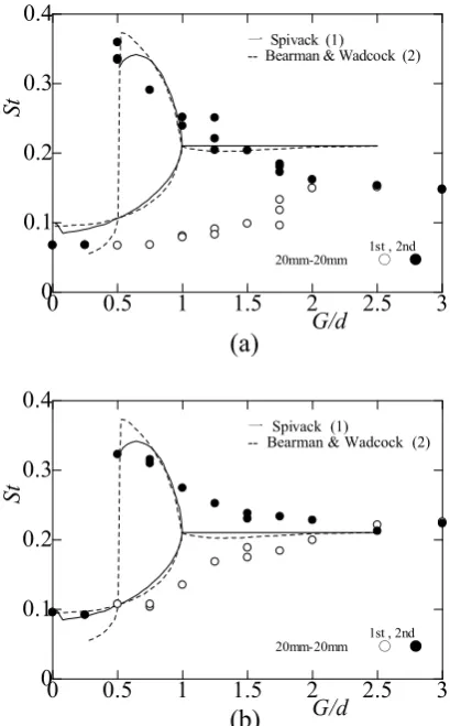
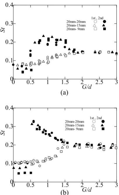
Fig. 6. Strouhal number in terms of gap ratio G/d in the case of (a) flat face suare cylinder and (b) sharp square cylinder
0 0.5 1 1.5 2 2.5 3
0 0.1 0.2 0.3 0.4
G/d
St
一 Spivack (1)
-- Bearman & Wadcock (2)
1st , 2nd 20mm-20mm ○ ●
15mm-15mm △ ▲
0 0.5 1 1.5 2 2.5 3
0 0.1 0.2 0.3 0.4
G/d
St
一 Spivack (1)
-- Bearman & Wadcock (2)
1st , 2nd 20mm-20mm ○ ●
15mm-15mm △ ▲
(a)
(b)
Fig. 7. Strouhal number in terms of gap ratio G/d in the case of (a) flat face triangular cylinder and (b) sharp triangular cylinder
0 0.5 1 1.5 2 2.5 3
0 0.1 0.2 0.3 0.4
G/d
St
一 Spivack (1)
-- Bearman & Wadcock (2)
1st , 2nd 20mm-20mm ○ ●
0 0.5 1 1.5 2 2.5 3
0 0.1 0.2 0.3 0.4
G/d
St
一 Spivack (1)
-- Bearman & Wadcock (2)
1st , 2nd 20mm-20mm ○ ●
(a)
(b)
circular cylinder and the same vortex street are formed. This vortex flow is called a "single vortex street." Figure 5(b) shows the state of the flow in gap ratio G/d=0.6. It is shown that the flow which passes through the gap between two circular cylinders inclines toward the 1st circular cylinder side. The length of the stagnation region of each circular cylinder differs, and the separating shear layer has been rolled individually. An aspect that a subordinate vortex street (1st circular cylinder side) unites to a dominant vortex street (2nd circular cylinder side) in each rolled separating shear layer is shown by the wake. In the wake of a long stagnation region, the width spreads and the period which a vortex rolls becomes long. In the wake of a short stagnation region, the width narrows and the period which a vortex rolls becomes short. As a result, two Strouhal numbers will be obtained in one gap ratio. As for figures 5(c) and (d), gap ratio G/d is in the state of G/d>1, and an aspect that the Karman vortex street is formed from each circular cylinder is shown. In these two figures, it is shown that the relationships of arrangement of the vortex of an alternate vortex street (Karman vortex street) differ. Although two pairs of vortex streets are symmetrically arranged in figure 5(c), two pairs of vortex streets are asymmetrically arranged in figure 5(d). In addition, the appearance of these flow patterns is not specified by gap ratio G/d, and replacement of two kind arrange (symmetrical
arrangement, asymmetrical arrangement) produces it intermittently. The frequency of the replacement is described later.
Fig. 8. Distribution of flow pattern, (1) coupled vortex streets, (2) biased gap flow, (3) single vortex street.
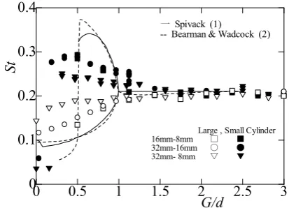
Fig. 9. Strouhal number in terms of gap ratio G/d in the case of unequal diameter circular cylinder.
0 0.5 1 1.5 2 2.5 3
0 0.1 0.2 0.3 0.4
G/d
St
一 Spivack (1)
-- Bearman & Wadcock (2)
Large , Small Cylinder 16mm-8mm □ ■
32mm-16mm ○ ●
32mm- 8mm ▽ ▼
case of the square cylinder, and in the case of the triangular cylinder, it is the same as that of the case of the circular cylinder. It is shown that the value of Strouhal number changes with gap ratio G/d. Accordingly, the following three regions exist. One of which is the region which is the same as the time of independent in the value of Strouhal number. The others are the region where two values of Strouhal number exist by mutual interference, and a region where the value of Strouhal number turns into a value of the half at the time of independent. These regions are made into the thing of explanation called for convenience the 1st region, the 2nd region, and the 3rd region, respectively. Although three regions existed, it turned out that the range in which each region appears changes with cross-sectional shape of the cylinder. The result about each cylinder is shown in figure 8. Here, the mutual interference region is shown by the shadow area. When the separating point is being fixed, it is shown that the range which carries out mutual interference is wider than the case where a separating point moves. In the case of sharp triangular cylinder, the range which carries out mutual interference is the widest, and it was found that the range of the 2nd region is also the maximum.
3.2 In the case of different size cylinder
It is one of the most interesting things of this study to investigate the mutual interference vortex flow between the cylinders from which natural vortex shedding frequency differs. Generally it is known that the value of Strouhal number changes with cross-sectional shape of the cylinder. For example, the Strouhal number in the case of single circular cylinder is 0.2, and the Strouhal number in the case of single flat face square cylinder is 0.14. Since the Strouhal number is defined by St=fd/U, if sizes differ also in the same cross-sectional shape, the vortex will be discharged on the frequency corresponding to the size. So, the experiment of the mutual interference vortex flow from two cylinders was conducted about the case where sizes differ in the same cross-sectional shape. Figure 9 shows the relationship between the gap ratio G/d and the Strouhal number with previous experimental results about the case of circular cylinder. Here, the diameter of each circular cylinder was used in calculation of the Strouhal number of each circular cylinder. Moreover, the diameter of a thick circular cylinder was used in calculation of the gap ratio. The Strouhal number characteristic in the case of different diameter showed the
characteristic variation by the gap ratio like the case of the same diameter. When the range of gap ratio G/d was 1.5<G/d<3, the vortex shedding characteristics of the 1st circular cylinder and the 2nd circular cylinder were the same, and it was found that two pairs of vortex flows have not interfered mutually. Moreover, when the value of gap ratio was small from about 1.5, it was found that the vortex shedding characteristic from each circular cylinder changes with mutual interference. There is a tendency for vortex shedding frequency to decrease with the 1st circular cylinder, and the vortex shedding frequency tends to increase with the 2nd circular cylinder. These tendencies are considered because there is peculiar character by the value of the ratios d2/d1 of the cylinder outer diameter. If the value of the ratios d2/d1 of the cylinder outer diameter becomes small, the difference of the value of the Strouhal number of two circular cylinders will become small.
Figure 10 shows the aspect of the vortex shedding from two circular cylinders that diameters differ. The diameter of the 1st circular cylinder is 32 mm, the diameter of the 2nd circular cylinder is 8 mm here, and the circular cylinder outer diameter ratios d2/d1 is 0.25. And also, the gap ratio is changed. The state of gap ratio G/d=1.6 is shown in figure 10 (a). The state of flow at this time is a single vortex flow. In figures 10 (b) and 10 (c), the gap ratio G/d shows the state of 0.3 and 0.6, respectively. The flow feature between two circular cylinders shows the "biased gap flow". The flow is inclining and flowing into the 2nd circular cylinder side. Two figures showed that the deviation condition of a biased gap flow decreased, when the cylinder gap increased. Figure 10 (d) is in the state of gap ratio G/d=2.5, and an aspect that the vortex street which became independent from each circular cylinder is formed is shown.
Fig. 10. Rep mm stre (c) vor presentative fl m and 8 mm co
eet G/d=0.16, Baiased gap f rtex streets G/
low patterns in ombination, (a (b) Baiased g flow G/d=0.6, /d=2.5
n the case of a) Single vort gap flow G/d= , (d) Coupled
(a
(b
(c
(d
32 tex =0.3, Fig vort regi vort 3.3 The perf cyli diff proj resu by m each and the mm dash cyli lege mea squ and It w Stro com)
b)
)
d)
g. 11. Strouha case of sharp sq 0 0 0 0.1 0.2 0.3 0.4 St 0 0 0 0.1 0.2 0.3 0.4 St tex shedding ion where s tex flow.
In the case
e experiment formed by va inder from wh fer. Here, calc
jection width ult of having
making the ci h figure of fig d the ordinate
diameters of m, 16 mm, and
hed line show inders of the end in the fig ans a flat fac uare cylinder, F d S.T. means
was found tha ouhal number mbined the cy
al number in te f (a) flat face s quare cylinder
0.5 1
0.5 1
characteristic scarcely chan
e of different
of mutual int arying the ga hich the shape culation of the of a larger cy experimented ircular cylind gure 12, the ab
is the Strouha f basic circula d 8 mm. More w the experim same diame ure, C.C. mea ce square cyl F.T. means a f a sharp triang at the tenden r to the gap linder from w
erms of gap ra square cylinde
r.
1.5 2
G/d
20mm-20mm
20mm-15mm 20mm- 9mm
1.5 2
G/d
1 20mm-20mm 20mm-15mm 20mm- 9mm
c was found e nging become
t shape cyli
terference vo ap ratio G/d c
e of the sectio e gap ratio wa ylinder. Figure
d combining er into the ba bscissa is the al number St. I ar cylinder ar eover, the soli mental result o eter for comp ans a circular linder, S.S. m flat face triang gular cylinder ncy of the va p ratio of th which the shap
(a)
(b)
atio G/d in the er and (b)
2.5 3
d
1st , 2nd ○ ●
△ ▲ □ ■
2.5 3
d
1st , 2nd
○ ● △ ▲
□ ■
except for the es the single
nder
rtex flow wa combining the on and the size as based on the e 12 shows the each cylinde asic section. In
gap ratio G/d In each figure re 32 mm, 25 id line and the of two circula parison. In the
cylinder, F.S means a sharp
gular cylinder r, respectively ariation of the
Fig. 12. Strouhal number in terms of gap ratio G/d in the case of circular cylinder.
0 0.5 1 1.5 2 2.5 3
0 0.1 0.2 0.3 0.4
G/d
St
一 Spivack (1)
-- Bearman & Wadcock (2)
□ F.S. 20mm
■ F.S. 15mm
◇ S.S. 20mm
◆ S.S. 15mm
▲ S.T. 20mm
▼ F.T. 20mm
○32
0 0.5 1 1.5 2 2.5 3
0 0.1 0.2 0.3 0.4
G/d
St
一 Spivack (1)
-- Bearman & Wadcock (2) ○25
□ F.S. 20mm
■ F.S. 15mm
◇ S.S. 20mm
◆ S.S. 15mm
▲ S.T. 20mm
▼ F.T. 20mm
0 0.5 1 1.5 2 2.5 3
0 0.1 0.2 0.3 0.4
G/d
St
一 Spivack (1)
-- Bearman & Wadcock (2) ○16
□ F.S. 20mm
■ F.S. 15mm
◇ S.S. 20mm
◆ S.S. 15mm
▲ S.T. 20mm
▼ F.T. 20mm
0 0.5 1 1.5 2 2.5 3
0 0.1 0.2 0.3 0.4
G/d
St
一 Spivack (1)
-- Bearman & Wadcock (2) ○ 8
□ F.S. 20mm
■ F.S. 15mm
◇ S.S. 20mm
◆ S.S. 15mm
▲ S.T. 20mm
▼ F.T. 20mm
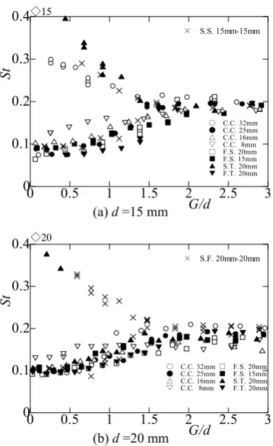
Fig. 13. Strouhal number in terms of gap ratio G/d in the case of flat face square cylinder.
0 0.5 1 1.5 2 2.5 3
0 0.1 0.2 0.3 0.4
G/d
St
□15
× F.S. 15mm-15mm
○ C.C. 32mm
● C.C. 25mm
△ C.C. 16mm
▽ C.C. 8mm
◇ S.S. 20mm
◆ S.S. 15mm
▲ S.T. 20mm
▼ F.T. 20mm
0 0.5 1 1.5 2 2.5 3
0 0.1 0.2 0.3 0.4
G/d
St
□20
× F.S. 20mm-20mm
○ C.C. 32mm
● C.C. 25mm
△ C.C. 16mm
▽ C.C. 8mm
◇ S.S. 20mm
◆ S.S. 15mm
▲ S.T. 20mm
▼ F.T. 20mm
and the size differ is close to the tendency of the variation in the case of two circular cylinders of the different
diameter. Moreover, it was found that an interaction region becomes wide. Although it is having seen also in the case of two circular cylinders with which diameters differ, the variation of the vortex shedding frequency in an interaction region is participating in the size of each other projection width. When own projection width is larger than the partner's projection width enough, the vortex shedding frequency decreases with reduction of the gap ratio. On the contrary, when own projection width is smaller than the partner's projection width enough, the vortex shedding frequency increases with reduction of the gap ratio. In the case of comparable projection width, it was found that the tendency changed with another cross-sectional shape. The ratio of projection width is about 0.8, the vortex shedding frequency has the tendency to increase with reduction of the gap ratio.
Figure 13 shows the result of having experimented combining each cylinder by making the flat face square cylinder into the basic section. In each figure of figure 13, the abscissa is the gap ratio G/d, and the ordinate is the Strouhal number St. In each figure, the width of the basic square cylinder is 15 mm and 20 mm. Moreover, the experimental result of the two square cylinders of the same width is also shown for comparison. It was found that the range of the mutual interference region becomes wide as compared with the case of the same width. Figure 14 shows the result of having experimented combining each cylinder by making the sharp square cylinder into the basic section. The figure shows the relationship
(d)
(a) d =32 mm
(b) d =25 mm
(c) d =16 mm
(d) d =8 mm
(a) d =15 mm
Fig. 14. Strouhal number in terms of gap ratio G/d in the case of sharp square cylinder.
0 0.5 1 1.5 2 2.5 3
0 0.1 0.2 0.3 0.4
G/d
St
○ C.C. 32mm
● C.C. 25mm
△ C.C. 16mm
▽ C.C. 8mm
□ F.S. 20mm
■ F.S. 15mm
▲ S.T. 20mm
▼ F.T. 20mm ◇15
× S.S. 15mm-15mm
0 0.5 1 1.5 2 2.5 3
0 0.1 0.2 0.3 0.4
G/d
St
◇20
× S.F. 20mm-20mm
□ F.S. 20mm
■ F.S. 15mm
▲ S.T. 20mm
▼ F.T. 20mm
○ C.C. 32mm
● C.C. 25mm
△ C.C. 16mm
▽ C.C. 8mm
Fig. 15. Strouhal number in terms of gap ratio G/d in the case of (a) flat face triangular cylinder and (b) sharp triangular cylinder.
0 0.5 1 1.5 2 2.5 3
0 0.1 0.2 0.3 0.4
G/d
St
▽20
× F.T. 20mm-20mm
○ C.C. 32mm
● C.C. 25mm
△ C.C. 16mm
▽ C.C. 8mm
□ F.S. 20mm
■ F.S. 15mm
◇ S.S. 20mm
◆ S.S. 15mm
▲ S.T. 20mm
0 0.5 1 1.5 2 2.5 3
0 0.1 0.2 0.3 0.4
G/d
St
△20
× S.T. 20mm-20mm
○ C.C. 32mm
● C.C. 25mm
△ C.C. 16mm
▽ C.C. 8mm
□ F.S. 20mm
■ F.S. 15mm
◇ S.S. 20mm
◆ S.S. 15mm
▼ F.T. 20mm
between the gap ratio and the Strouhal number, and also shows the experimental result of the two square cylinders of the same width for comparison. Here, the projection width of the square cylinder in figure 14(a) is 21.21 mm, and the projection width of the square cylinder in figure 14(b) is 28.28 mm. The experimental result in this case was the same as the experimental result of the flat face square cylinder. Accordingly, as compared with the case of the same width, it was found that the range of the mutual interference region becomes wide.
Figure 15 shows the result of having experimented combining each cylinder by making the right triangular cylinder into the basic section. The figure shows the relationship between the gap ratio and the Strouhal number, and also shows the experimental result of the two triangular cylinders of the same width for comparison. The experimental result of the flat face triangular cylinder and the experimental result of the sharp triangular cylinder are shown in figures 15(a) and 15 (b), respectively. It was found that the range of the mutual interference region scarcely changes. In the case of the vortex shedding from the square cylinder or the triangular cylinder, as compared with the vortex shedding from the circular cylinder, the vortex discharged from another cylinder does not affect the vortex shedding from its own cylinder. However, the relationship of the Strouhal number to the gap ratio changes with combination of another cylinder, respectively. The flow pattern in this case showed the variation by the gap ratio like the case of two cylinders of the same width or
different width. The flow pattern changed to the single vortex street, the bias gap flow, and the couple vortex flow as the gap ratio became large, but the range of each region changed with the combination partner's cylinders.
3.4 Arrangement of two vortex streets
In the 1st region where the gap ratio G/d is larger than 1.0, the aspect of the arrangement of the vortex street discharged from each cylinder corresponding to the gap ratio was investigated. Figure 16 is a diagram for judging the aspect of the arrangement of the vortex street, and shows two pairs of vortex streets schematically. Distinction of the aspect of the arrangement of vortex streets was performed by the arrangement relationship of the vortex of two pairs of vortex streets which exists inside mutually. It was classified into three kinds according to the value of the interval "s" of A vortex and B vortex. When the value of the interval s was s=0, the arrangement of vortex street was called "in-phase arrangement". On the other hand, when the value of the interval s was s=l/2, the arrangement of vortex street was called "out-of-phase arrangement". In the case where the value of the interval s is s<l/4, or s>3l/4, the arrangement of vortex street was called "un-known arrangement". Here, the "un-known arrangement" means the arrangement which is not in the in-phase arrangement or the out-of-phase arrangement. Figure 17 shows the rate of
(a)
(b) (a) d =15 mm
(b) d =20 mm
(a)
Fig. 16. Exp cyl pha
an abundance for every cyli an arrangeme times of vort that two or intermittently paid especial square cylind triangular cy arrangement conditions.
4 Conclus
About the mu a pair of cylin in parallel, characteristic cylinder was obtained.
(1) In the characteristic cylinder, a sq shown. Abou interference, narrowest is the widest is t (2) In the circular cylin wide, but in changeless.
(3) In the characteristic shedding cha the process combination.
(4) In the flow patterns coupled vorte (5) Three phase, out-of region (the 1 arranged inde two or mo intermittently
position of vor linders, s=0: in ase case, s<l/4
e ratio of three inder. Here, th ent state was ex shedding. more arrang y, and have ap
lly the case o der, and in the
ylinder, it appears in h
sions
utual interferen nders of three
the investi when varyin performed. T
case of the s about three quare cylinder ut the regio
it was found the circular c the sharp trian e case of the nder, the mutu
the case of s
case of differ became the aracteristic in of variation
e wake of two s (single vorte ex streets) occ e kinds of vo f-phase and un 1st region) in ependently. In ore arrangem y. Moreover,
rtex formation n-phase case, 4 or s>3l/4: un
e kinds of the he rate of an a s determined In each cylin gement patte ppeared. When
of G/d=2.5-3 e case of G/d=
became clea high probabili
nce vortex flo kinds of com igation of ng the arrange The following
same size, the kinds of cyli r, and triangu n which car d that the ca cylinder and t ngular cylinde different siz ual interferenc
square cylind
rent shape, the same tenden the case of d n changed w
o bluff cylind ex street, bias
urred.
rtex street ar n-known) wa which two v n the region, ment patterns it became
n behined two s=l/2: out-of-n-known case.
arrangement s abundance rati
by observing nder, it was fo erns interchan n its attention of the flat =3 of the flat ar that spe ity depending
ow produced f mbination arran
vortex shed ement interva
conclusions w
e vortex shed inders (a circ ular cylinder) rries out mu ase of being the case of b er.
ze, in the cas ce region bec der, it was alm
e vortex shed ncy as the vo
different size, with partners
der, three kind sed gap flow
rrangement (in s observed in vortex streets it was found s were chan clear that o . Fig state io of g 50 ound nged was face face cific g on from nged ding al of were ding cular was utual the eing e of came most ding ortex , but s of ds of and nch-n the s are that nged the part app
Re
1. 2. 3.4.
5.
6.
7.
g. 17. Appea various (b) In t of un-k 0 1 0 0.2 0.4 0.6 0.8 1 In -P ha se/ n 0 1 0 0.2 0.4 0.6 0.8 1 Out-of -P ha se /n 0 1 0 0.2 0.4 0.6 0.8 1 Un -k no w n/ n ticular arrang pears in high p
eferences
H.M. Spivak P.W. Bearm 499-511 (19 T. Kobayash 1452-1461 ( K. Ohumi, K Suppl. 1, 35-K. Ohumi, (1995) M. Moriya e 676, 3310-33 Y. Yokoi, S 138 (2004)arance of thre s gap ratio, (a the case of ou known .
1 2 3
1 2 3
1 2 3
ement which probability.
k, J. Aeronaut man, A.J. Wad
73)
hi, Trans. Jpn 1976) K. Imaichi, E.
-40 (1990)
J. Vis. Soc.
et al., Trans. 315 (2002)
ci. and Eng. R (b
(c (a
ee typical flo a) In the case ut-of-phase, (
3 4 5
G/d ○ △ ▽ □ ◇
3 4 5
G/d ○ △ ▽ □ ◇
3 4 5
G/d ○ △ ▽ □ ◇ is dependent
. Sci., 13, 289 dcock, J. Fluid
n. Soc. Mech.
. Tada, J. Vis
Jpn, 15 Sup
Jpn. Soc. Me
Report of ND b)
c) a)
ow pattern at e of in-phase
c) In the case
5 6
○ C.C.
△ S.T.
▽ F.T.
□ F.S.
◇ S.S.
5 6
○ C.C.
△ S.T.
▽ F.T.
□ F.S.
◇ S.S.
5 6
○ C.C.
△ S.T.
▽ F.T.
□ F.S.
◇ S.S.
on condition
9-297 (1946) d Mech., 61-3
Eng., 42-357
s. Soc. Jpn, 10
ppl. 1,217-220
ech. Eng., 68