Structural Behavior Of Self-Compacting Deep
Beam With Opening Strengthened By
(CFRP)-Analytical Study
Ragheed Fatehi Makki, Hussein A. AbdulhusseinAbstract: The main aim of this study is to investigate thoroughly the structural behaviour of (SCC) deep beams that contain openings and reinforced with CFRP strips around the holes, by using the nonlinear finite element program (ANSYS version 16.1). Thirteen beam specimens, one sold reference deep beam and twelve beams with different shapes of openings, i.e. circle, square, rectangle and rhombus, without shear reinforcement were simulated and analyzed by (ANSYS) under four-point loading setup. The beams with openings were equally divided into two groups; with and without CFRP strips, as a reference group. Each reference beam has a strengthened beam to compare with while the solid beam was the reference for all the twelve beams. The results have shown that, for the same area of perforation, the reduction in the SCC deep beam specimens’ shear resistance depends on the perforation’s shape and orientation. The beam strengthened by CFRP with symmetric circular openings resists higher load than the same beam with square or rhombus openings, about 40 and 70% respectively. Also, a beam specimen, strengthened by CFRP, contains horizontal rectangular- shaped openings load resistance is 50% higher than a specimen with vertical rectangular openings of the same dimensions. In addition, the CFRP sheets strengthening effects are higher at the perforations with edges, such as square and rectangle, than the circular shape as the sheets are effective in resisting 19 the stress concentration at the sharped edges.
Index Terms: Self-Compacting Concrete (SCC) ; Deep beams; Openings; Strengthening; CFRP. Sheets, ANSYS. ————————————————————
1
I
NTRODUCTIONRC deep-beams are structural elements with depth much higher than usual if compared with their span, while the width, in the perpendicular dimension of the deep beams, is significantly less than both span or depth(Nilson, 2016).The ACI code ,[ACI Committee 318 (ACI 2014)], defines the (deep–beams) as members with clear span ( ) less than or equal four-times of overall member height (h) (i.e. ≤4h ) or a part of a beam loaded by a straight load placed in a distance (a), less than or equal to 2h, from the centre of support where the load on one side and the support on the opposite side. In tall buildings, the deep beams are commonly designed as load-distribution structural segments which transfer loads from one or more columns to other columns. Furthermore, deep– beams are utilized in some pile caps, offshore structures and foundation walls, (Wight & Macgregor, 2009.) ;( Russo, Venir, & Pauletta, 2005). The using of deep-beams in the tall buildings has increased the need to provide openings in the beam’s web that facilitate the accessibility of fundamental services such as ducts of ventilating and air conditioning, water and drained pipes. However, these openings typically lead to a decrease in the resistance of the beams. This reduction in beam’s resistance is affected, among the other factors, by the size and shape of the openings (El Maaddawy & Sherif, 2009). Alsaeq in (2013)(Alsaeq, 2013) presented finite element analyses to increase the strength of (RC) deep beam which contained large openings. Two ways of strengthening were investigated in the study; firstly, using steel bars near around the openings; secondly, using CFRP laminates around the openings.
The software that used for simulation and analysis of the deep-beams was (ANSYS 12.1.) The study concluded that using steel bars in strengthening improved the ultimate strength by 48% compared to 29% for CFRP laminates. Moayad M. Kassim et. al. in 2015 (Kassim, Salahaldin, & Ali, 2015) carried out a numerical study using a finite element method and ANSYS software program. The research aimed to study the impact of using CFRP sheets n improving the shear resistance of deep-beams containing large web cut off. The variables adopted in their research were the fiber direction of CFRP sheets and the thickness of used CFRP externally bonded. This study concluded that the strengthened beams strength of the beams by (25, 53 and 59) % for vertical CFRP sheets with (0.7, 1.4 and 2.8) mm in thickness individually. While, the horizontal strengthening of beams upgrading the beams’ capacity by (54, 78 and 90) % for the same above thicknesses respectively. It is worth mentioning that the ring CFRP sheets improved the strength of the beams by 85, 92 and 97% for the three layout used in which sheet thickness was 0.1.
Chin et. Al in 2011(S. C. Chin, Shafiq, Kusbiantoro, & Nuruddin, 2014) studied the effect of both the location of a large square opening and their strengthening by using CFRP sheet around the opening on the beams’ performance. The study included cast and tested six deep beams with dimensions (120x300x2000) mm. Two of the six samples were sold reference beams and three beams were un-strengthened beams with one large square opening, (210 x210) mm, placed at distances of (0.5 d, d and 1.5 d). While the last beam was strengthening by CFRP. In 2018 Jassem, Hayder (Jassem, 2018) analysis 8 reactive powder concrete(RPC) deep beams contains square opening and strengthened by different layouts of CFRP by using non-linear finite element program (ANSYS 15). The analysis results indicate that ANSYS analysis software suitable for simulating the properties of reactive powder concrete members. The numerical simulation of tested beams was done by a non-linear finite element (FE) in which a two-dimensional (2D) modelling was adopted for this study. ____________________________
Ragheed Fatehi Makki is currently a assistance professor of structural engineering in Kufa University, Country-Iraq. E-mail: [email protected]
2
D
ETAILSO
FS
IMULATINGS
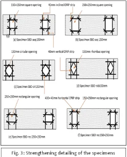
PECIMENSIn this study, one solid reference beam and twelve deep beams with different shapes of openings were constructed by SCC and tested under symmetrically four-point loading system. All deep beams had a total length of (1400 mm), a width of (150 mm) and an overall depth of (400 mm). The clear span of the deep beams was 1200 mm, and free ends of those beams extended by 100 mm beyond the centre of the support. the clear span of 1200 mm between the supports. Steel plates, of (100mm x 150mm x 10mm), were used under the applied load. The Figures (1,2 and 3) shown the details of the simulating beams.
3
F
INITEE
LEMENTM
ODELINGA large number of connected nodes and elements, which have different behaviour according to each specified materials, were used in the non -linear finite simulations of deep beams. (ANSYS 16.1) was utilised because it contains a large number of various elements that can simulate the homogenous and non-homogenous materials.
The eight nodes element (SOLID65) was used to simulate the self-compact concrete.
(LINK180) element represented the flexural steel bars.
CFRP sheets simulated as a Shell element (shell41).
The brick element (SOLID185) simulated the loading and bearing plates modelling.
Figure (4) shown Elements used in modelling the beams.
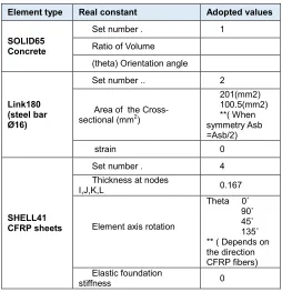
3.1 Real Constant
Table 1 Real Constant Of The Elements Used In Modelling
Element type Real constant Adopted values
SOLID65 Concrete
Set number . 1
Ratio of Volume (theta) Orientation angle
Link180 (steel bar Ø16)
Set number .. 2
Area of the Cross-sectional (mm2)
201(mm2) 100.5(mm2) **( When symmetry Asb =Asb/2)
strain 0
SHELL41 CFRP sheets
Set number . 4
Thickness at nodes
I,J,K,L 0.167
Element axis rotation
Theta 0˚ 90˚ 45˚ 135˚ ** ( Depends on the direction CFRP fibers) Elastic foundation
stiffness 0
3.2 Material Properties
In the numerical simulation software’s such as ANSYS, the properties of the materials that were used to create the representation of the structural members define the behaviour of that member during the finite element analysis. For instance, a reinforced concrete member can behave similar to a combined system although it formed originally from two different materials, concrete and steel reinforcement, which is the case of the normal or self-compacting concrete. The steel reinforcement usually regarded as a uniform material, homogenous, which has similar behaviour in compression and tension (specially stress strain relationship). In contrary, due to the properties of concrete ingredients, such as cement mortar, coarse and fine aggregates, the concrete behaves differently in tension and compression which make it a quasi-brittle material. In this study, the ANSYS software a full bond between the different materials used in the modelling was assumed. The eight nodes element (solid 65) is able to simulate the crushing and cracking of concrete due to the stresses in both compression and tension. This is the main difference between solid 65 and element (solid 185) which was used for modelling bearing plates at supports and loading point. The steel reinforcement simulated by uniaxial 3D bar element (LINK180) as a discrete straight element. Finally, (shell 41), which is a 4 nodded member, was used for modelling CFRP sheets. Tables (2,3,4 and 5) shows the properties of the elements used in the beams’ simulations.
Table 2 Material Properties For (Solid 65)
Linear. Isotropic Modulus of Elasticity, MPa Ex
28120**
From experimental work results
Poison’s Ratio PRXY 0.2
Concrete. Parameters
Transfer Coefficient of Open Shear
Cracks 0.1
Transfer Coefficient of Closed Shear
Cracks 0.35
Concrete Cracking Stress 3.63
Concrete Crushing Stress 35
Tensile Crack Factor 0.68
Table 3 Material Properties for (Link 180)
Material Properties for (Link 180) Ø16 Linear Isotropic
Modulus of Elasticity, MPa 2000
Poison’s Ratio 0.3
Bilinear Isotropic
Yield Stress, MPa 550
Tangent Modulus, MPa 2000
Table 4 Materials Properties For Shell 41
Material Properties for (Shell 41)
Linear orthotropic
EX 230000
EY 1
EZ 1
PRXY 0.3
PRYZ 0
PRXZ 0
GXY 1
GYZ 1
GXZ 1
Table 5 Material Properties for (solid 185)
Material Properties for (solid 185) Linear Isotropic
Modulus of Elasticity, MPa 2000
4
G
EOMETRY OF THE SPECIMENS:
The simulation of the tested beams in ANSYS 16.1 software was carried out for one-quarter of the beam due to the symmetry of the beams in the following configurations: supports, opening location, loading point reinforcement and concrete, see Figure 5 (A &B). This system of modelling reduced significantly both the run time and the computer drive space requirement.
5
A
PPLIEDL
OADS ANDB
EAM’
SB
OUNDARYC
ONDITIONSDuring the beams’ testing, bearing steel plates with dimensions of (100mm x 150mmx 10mm) were placed at the support and under the loading points to avoid the problems of stress concentration. In the finite element representation, this plate was modelled in the same dimensions and the load was distributed on one line nodes within the plate centreline following approximate the procedure that shares of the exterior node is half that of the interior one as shown in Figure 6. The majority of the previous studies approved this approximate as acceptable simulation with consideration to the area around
6
O
PTIMISING THES
IZE OF THEE
LEMENTThe aim of this step is to find the most appropriate finite element mesh to complete the FE analysis with acceptable accuracy and suitable running time. This aim was achieved by the observation of the effect of mesh density on the mid-span deflection. Therefore, three trials were done to analysis the control beam with different mesh densities, 12.5 mm x 12.5 mm, 25 mm x 50 mm and 25 mm x 25 mm with similar depth of 25mm, as shown in the Figure 7. As a result, the best meshing which satisfy the accuracy of the tests’ results in a suitable time to simulate the deep beam was (25 x 25x 25) mm.
7
R
ESULTS OFF
INITEE
LEMENTA
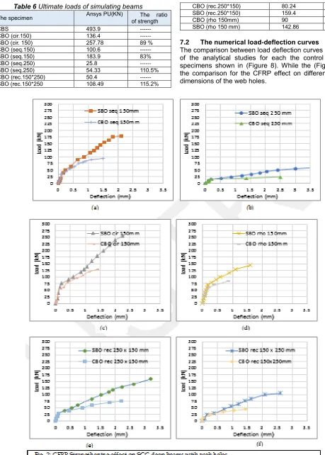
NALYSISAll the 13 beams were simulated and analysed by ANSYS 16.1 software. The results included the ultimate load of each beam and compare the load-deflection curve for control and strengthen beams, as the following:
7.1 Numerical results of the ultimate load
Table 6 Ultimate loads of simulating beams
The ratio of strength Ansys PU(KN)
The specimen
--- 493.9
CBS
--- 136.4
CBO (cir.150)
89 % 257.78
SBO (cir. 150)
--- 100.6
CBO (seq.150)
83% 183.9
SBO (seq.150)
--- 25.8
CBO (seq.250)
110.5% 54.33
SBO (seq.250)
--- 50.4
CBO (rec.150*250)
115.2% 108.49
SBO (rec.150*250
--- 80.24
CBO (rec.250*150)
98.6% 159.4
SBO (rec.250*150)
--- 90
CBO (rho 150mm)
58.7% 142.86
SBO (rho 150 mm)
7.2 The numerical load-deflection curves
8
CONCLUSIONS:
Several conclusions can be drawn from the non –linear finite element investigations:
1. The CFRP sheets installation have increased the load capacity of the deep beam with openings; however, in different values depending on the opening’s shape and its dimensions.
2. The CFRP sheets effect is higher at the shapes with edges, square and rectangle, than the circular shape as the sheets are effective in resisting the stress concentration at the sharped edges.
3. The deep beam with the circular shape, SBO cir 150 mm, resisted a higher load than the other beams the same as its reference beam.
4. The highest effect for the CFRP installation was increasing the failure load by 115.2%% at the beam with rectangle openings of 150 x 250 mm.
5. The lowest effect for the CFRP strengthen was in SBO rho 150 mm, about 58.7%.
9
R
EFERENCES[1] ACI Committee 318, "Building Code Requirements for Structural Concrete (ACI 318M-14) and Commentary," American Concrete Institute, Farmington Hills, MI 48331, USA, 2014, 520 pp.
[2] Alsaeq H.M. ,2014. Enhancing the Structural Behaviour of R.C. Deep Beams with Openings. Journal of Babylon University (Engineering Sciences). [3] ANSYS Help V 16.1. A finite element computer software theory and user manual for nonlinear structural analysis.
[4] Chin, S. C., Shafiq, N., Kusbiantoro, A., & Nuruddin, M. F. (2014). Reinforced Concrete Deep Beams with Openings Strengthened Using FRP – A Review. Advanced Materials Research.
[5] El Maaddawy, T. and Sherif, S., 2009. FRP composites for shear strengthening of reinforced concrete deep beams with openings. Composite Structures, 89(1), pp.60-69.
[6] Jassem, H. A. A. (2018). Structural Behavior of
[7] Russo, G., Venir, R., & Paulette, M. (2005). Reinforced concrete deep beams - Shear strength model and design (vol 102, pg. 429, 2005). ACI Structural Journal, 102(102), 913.