www.ijiarec.com
Author for correspondence:
Volume-7 Issue-2
International Journal of Intellectual Advancements
and Research in Engineering Computations
Analysis of microstrip patch antenna for 5G mobile communications
Mrs.P.Kokila
1, Logeshwaran.N
2, NarayanaMoorthy.S
2, Nithyanandhan.S
2, Shobana.M
21
Assitant Professor, Department of ECE, Nandha Engineering College, Erode ,Tamilnadu, India
2
Under Graduate, Department of ECE, Nandha Engineering College, Erode, Tamilnadu ,India
ABSTRACT
Mobile technology has experienced tremendous growth and has brought expeditious change in the way of connecting, information sharing, and empowering people around the globe. In the future, fifth generation (5G) wireless system will bring a new era and is expected to fulfill the increasing demands of higher mobility, higher efficiency, higher data rates, better connectivity, better adaptability and better flexibility than the current fourth generation mobile networks. To provide the data rates in the Gb/s range, frequency band from 6 to 100 GHz is now being considered globally. In this paper we analyze the antennas with three different frequency ranges for the better establishment of 5G network.
Index Terms- Antenna Analysis, Communications, Microstrip Patch Antenna, Performance Analysis.
INTRODUCTION
An antenna is an electrical conductor or a system of conductors which is “that part of a transmitting or receiving system that is designed to radiate or receive electromagnetic waves”. A microstrip patch antenna is a metallic strip or patch mounted on a dielectric layer (substrate) over a ground plane. They are used for high performance in extreme applications. Microstrip patch antennas are used for mobile phone applications due to their small size, low cost, ease of production etc. The MSA has proved to be an excellent radiator for many applications because of its several advantages. Here we analyze the gain, directivity, return loss, input impedance and efficiency for the frequency range of 5.6 GHz, 6.4 GHz and 7.6 GHz that provide spectacular comparison for establishment of network.. And this helps the future communication, fifth generation (5G) wireless system will bring a new era and is expected to fulfill the increasing demands of higherThe research methodology inculcates the designing of the slot couple patch antenna. This designed antenna structure is fed by using single coaxial probe feed. After feeding the antenna structure these designed antennas are further
simulated over HFSS simulation software, a FET
based
simulation software.MICROSTRIP PATCH ANTENNA
Design of Microstrip Patch Antenna
3003
Kokila P et al., Inter. J. Int. Adv. & Res. In Engg. Comp., Vol.–07(02) 2019 [3002-3014]
inset-fed microstrip antenna provides impedance control with a planar feed configuration [1-5].
The structure of the Micro strip patch antenna consists of a thin square patch on one side of a dielectric substrate and the other side having a plane to the ground. In its most fundamental form, a Micro strip antenna consists of a radiating patch on one side of a dielectric substrate which has a ground plane on other side as shown in the figure below. The patch is generally made of conducting material such as copper or gold. The basic antenna element is a strip conductor of length L and width W, on a dielectric substrate. The thickness of the patch being h with a height and thickness t is supported by a ground plane. The rectangular patch antenna is designed so that it can operate at the resonance frequency. The length of the patch for arectangular patch antenna normally would be 0.333λ<L<0.5λ.Where, λ being the free space wavelength. The thickness of the patch is selected to be in such a way that is t<<λ.
Design Equations
1. For an efficient radiator, a practical width that leads to good radiation efficiencies is
2. Determine the effective dielectric constant of the microstrip antenna
3. Once W is found using, determine the extension of the length _L.
4. The actual length of the patch can now be determined by solving for L.
Structure of Patch Antenna
3004
Kokila P et al., Inter. J. Int. Adv. & Res. In Engg. Comp., Vol.–07(02) 2019 [3002-3014]
Figure 2.1 Structure of Patch Antenna
Substrate
The first step in designing an antenna is to choose an appropriate substrate. The substrate in micro strip antennas is principally needed for the mechanical support of the antenna. To provide this support, the substrate should consist of a dielectric material, which may affect the electrical performance of the antenna, circuits and transmission line. A substrate must, therefore, simultaneously satisfy the electrical and mechanical requirements, which is sometimes difficult to meet. We have different dielectric substrate frequently used in microstrip patch antenna to enhance overall efficiency of antenna. Various substrates like foam, duroid, benzocyclobutane, roger 4350, epoxy, FR4, Duroid 6010 are in use to achieve better gain and bandwidth. A dielectric substrate is a insulator which is a main constituent of the microstrip structure, where a thicker substrate is considered because it has direct proportionality with bandwidth whereas dielectric constant is inversely
3005
Kokila P et al., Inter. J. Int. Adv. & Res. In Engg. Comp., Vol.–07(02) 2019 [3002-3014]
values and electrical insulating qualities in both dry and humid conditions. These attributes, along with good fabrication characteristics, lend utility to this grade for a wide variety of electrical and mechanical applications.Grade designations for glass epoxy laminates are: G10, G11, FR4, FR5 and FR6. Of these, FR4 is the grade most widely in use today. G-10, the predecessor to FR-4, lacks FR-4's self-extinguishing flammability characteristics. Hence, FR-4 has since replaced G-10 in most applications.FR-4 epoxy resin systems typically employ bromine, a halogen, to facilitate flame-resistant properties in FR-4 glass epoxy laminates. Some applications where thermal destruction of the material is a desirable trait will still use G-10 non flame resistant.
Feeding Techniques
There are mainly four basic methods for the feeding to these antennas Probe Coupling Method,
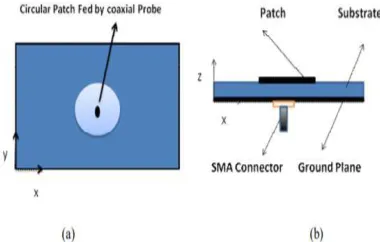
Microstrip Line Feeding Method, Aperture Coupled Microstrip ,Feed Method Proximity Coupling Probe Coupling Method: Coupling of power to the microstrip patch antenna can be done by probe feeding method. The inner conductor of the probe line is connected to patch lower surface through slot in the ground plane and substrate material . To get perfect impedance matching we need to find out the location of the feed point over the antenna element. Design simplicity and input impedance adjustment through feed point positioning, makes this feeding method popular. But there are some limitations also like larger lead for thicker substrate, difficulty in soldering for array elements etc.
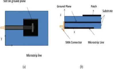
Microstrip Line feeding Method: Using microstrip line we can give excitation to the antenna as shown in the figure. This method is very simple to design and fabricate.
Figure 2.2 Probe Coupling Method a) Top View b) Side View
But this technique suffers from some limitations. If substrate thickness is increased in the design then the surface waves and the spurious radiation also increases. Because of that the
undesired cross polarization radiation arises. Microstrip line feeding can be used in the conditions where performance of the antenna is not a strict matter.
3006
Kokila P et al., Inter. J. Int. Adv. & Res. In Engg. Comp., Vol.–07(02) 2019 [3002-3014]
Figure 2.3 Geometry of direct microstrip feed microstrip patch antenna a) Top view b) Side view
Figure 2.4 Geometry of Proximity Coupled Method microstrip patch antenna a) Top view b) Side view
Aperture Coupled Feed Method: This method employs ground plane between two substrates. A slot will be placed on the ground plane and feed line will be placed on lower substrate. This will be electromagnetically connected to patch on the
upper substrate through the ground plane slot. One should take care about substrate parameters and they have to choose in a way that feed optimization and independent radiation functioning can exist.
Figure 2.5 Geometry of Aperture Coupled Feed Method microstrip patch antenna a) Top view b) Side view
MicrostripPatch
A patch antenna is a type of radio antenna with a low profile, which can be mounted on a flat surface. It consists of a flat rectangular sheet or
3007
Kokila P et al., Inter. J. Int. Adv. & Res. In Engg. Comp., Vol.–07(02) 2019 [3002-3014]
a length of approximately one-half wavelength of the radio waves. The radiation mechanism arises from discontinuities at each truncated edge of the microstrip transmission line. The radiation at the edges causes the antenna to act slightly larger electrically than its physical dimensions, so in order for the antenna to be resonant, a length of microstrip transmission line slightly shorter than one-half the wavelength at the frequency is used. The patch antenna is mainly practical at microwave frequencies, at which wavelengths are short enough that the patches are conveniently small. It is widely used in portable wireless devices because of the ease of fabricating it
on printed circuit boards. Multiple patch antennas on the same substrate (see image) called microstrip antennas, can be used to make high gain array antennas, and phased arrays in which the beam can be electronically steered. A variant of the patch antenna commonly used in mobile phones is the shorted patch antenna, or planar inverted-F antenna (PIFA). In this antenna, one corner of the patch (or sometimes one edge) is grounded with a ground pin. This variant has better matching than the standard patch. Another variant of patch antenna with the partially etched ground plane, also known as printed monopole antenna, is a very versatile antenna for dual-band operations.
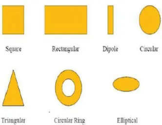
Figure 2.6 Common Shape OfMicrostrip Patch Antenna
Analysis Method
Finite Element Method
The Finite Element Method (FEM), unlike the MoM, is suitable for volumetric configurations. In this method, the region of interest is divided into a number of finite surfaces or volume elements depending upon the planar or volumetric structures to be analyzed. These discredited units, generally referred to as finite elements, can be any well-defined geometrical shapes such as triangular elements for planar configurations and tetrahedral
3008
Kokila P et al., Inter. J. Int. Adv. & Res. In Engg. Comp., Vol.–07(02) 2019 [3002-3014]
OUTPUT OF 5.6 GHZ
Figure 3.1 Structure of 5.6GHZ patch antenna
Figure 3.3 VSWR of 5.6GHZ patch antenna
3009
Kokila P et al., Inter. J. Int. Adv. & Res. In Engg. Comp., Vol.–07(02) 2019 [3002-3014]
Figure 3.2 Impeadance of 5.6GHZ patch antenna
Figure 3.4 S Parameter of 5.6GHZ patch antenna
Figure 3.6 Gain of 5.6GHZ patch antenna
OUTPUT OF 6.5 GHZ
3010
Kokila P et al., Inter. J. Int. Adv. & Res. In Engg. Comp., Vol.–07(02) 2019 [3002-3014]
Figure 4.2 VSWR of 6.5GHZ patch antenna
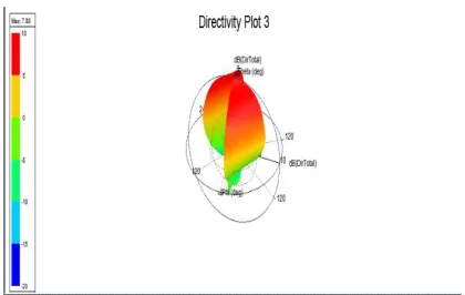
Figure 4.3 Directivity of 6.5GHZ patch antenna
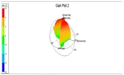
Figure 4.4 Gain of 6.5GHZ patch antenna
3011
Kokila P et al., Inter. J. Int. Adv. & Res. In Engg. Comp., Vol.–07(02) 2019 [3002-3014]
OUTPUT OF 7.5 GHZ
Figure 5.1 S Parameter of 7.5GHZ patch antenna
Figure 5.2 VSWR of 6.5GHZ patch antenna
Figure 5.3 Directivity of 6.5GHZ patch antenna
3012
Kokila P et al., Inter. J. Int. Adv. & Res. In Engg. Comp., Vol.–07(02) 2019 [3002-3014]
Figure 5.5 Impedance of 7.5 patch antenna
ANALYSIS OF ANTENNA
In electromagnetics, an antenna's power gain or simply gain is a key performance number which combines the antenna's directivity and electrical efficiency. In a transmitting antenna, the gain describes how well the antenna converts input power into radio waves headed in a specified direction. In a receiving antenna, the gain describes how well the antenna converts radio waves arriving from a specified direction into electrical power. When no direction is specified, "gain" is understood to refer to the peak value of the gain, the gain in the direction of the antenna's main lobe. A plot of the gain as a function of direction is called the radiation pattern. Antenna gain is usually defined as the ratio of the power produced by the antenna from a far-field source on the antenna's beam axis to the power produced by a hypothetical lossless isotropic antenna, which is equally sensitive to signals from all directions. Usually this ratio is expressed in decibels, and these units are referred to as "decibels-isotropic" (dBi). An alternative definition compares the received power to the power received by a lossless half-wave dipole antenna, in which case the units are written as dBd. Since a lossless dipole antenna has a gain of 2.15 dBi, the relation between these units. For a given frequency, the antenna's effective area is proportional to the power gain. An antenna's effective length is proportional to the square root of the antenna's gain for a particular frequency and radiation resistance. Due to reciprocity, the gain of any reciprocal antenna
when receiving is equal to its gain when transmitting.
Directive gain or directivity is a different measure which does not take an antenna's electrical efficiency into account. This term is sometimes more relevant in the case of a receiving antenna where one is concerned mainly with the ability of an antenna to receive signals from one direction while rejecting interfering signals coming from a different direction.
RADIATION PATTERN
3013
Kokila P et al., Inter. J. Int. Adv. & Res. In Engg. Comp., Vol.–07(02) 2019 [3002-3014]
graphs can be drawn using cartesian (rectangular) coordinates or a polar plot. This last one is useful to measure the beamwidth, which is, by convention, the angle at the -3dB points around the max gain. The shape of curves can be very different in cartesian or polar coordinates and with the choice of the limits of the logarithmic scale. The four drawings below are the radiation patterns of a same half-wave antenna.
EFFICIENCY
Efficiency is the ratio of power actually radiated by an antenna to the electrical power it receives from a transmitter. A dummy load may have an SWR of 1:1 but an efficiency of 0, as it absorbs all the incident power, producing heat but radiating no RF energy; SWR is not a measure of an antenna's efficiency. Radiation in an antenna is caused by radiation resistance which cannot be directly measured but is a component of the total resistance which includes the loss resistance. Loss resistance results in heat generation rather than radiation, thus reducing efficiency. Mathematically, efficiency is equal to the radiation resistance divided by total resistance (real part) of the feed-point impedance. Efficiency is defined as the ratio of the power that is radiated to the total power used by the antenna; Total power = power radiated + power loss.
IEEE defines bandwidth as "The range of frequencies within which the performance of the antenna, with respect to some characteristic, conforms to a specified standard."In other words, bandwidth depends on the overall effectiveness of the antenna through a range of frequencies, so all of these parameters must be understood to fully characterize the bandwidth capabilities of an antenna. This definition may serve as a practical definition, however, in practice, bandwidth is typically determined by measuring a characteristic such as SWR or radiated power over the frequency range of interest. For example, the SWR bandwidth is typically determined by measuring the frequency range where the SWR is less than 2:1. Another frequently used value for determining bandwidth for resonant antennas is the -3dB Return Loss value.
DIRECTIVITY
Antenna directivity is the ratio of maximum radiation intensity (power per unit surface) radiated by the antenna in the maximum direction divided by the intensity radiated by a hypothetical isotropic antenna radiating the same total power as that antenna. For example, a hypothetical antenna which had a radiated pattern of a hemisphere (1/2 sphere) would have a directivity of 2. Directivity is a dimensionless ratio and may be expressed numerically or in decibels (dB). Directivity is identical to the peak value of the directive gain; these values are specified without respect to antenna efficiency thus differing from the power gain (or simply "gain") whose value is reduced by an antenna's efficiency.
GAIN
low-3014
Kokila P et al., Inter. J. Int. Adv. & Res. In Engg. Comp., Vol.–07(02) 2019 [3002-3014]
gain (as long as the base station is within range, the antenna can be in an any orientation in space).
CONCLUSION
This paper presents a slot coupled patch antenna simulated at different frequencies from 5.6 GHz to 7.5 GHz as shown in figures 3.1-4.5 where fig 3.1-fig 3.5 represents the radiation pattern of the antenna at 5.6 respectively. Fig 3.1 to fig 3.5 represents return loss characteristics of the antenna at these three frequencies respectively. The patch and the ground plane are separated by a material with low dielectric constant FR4 epoxy and an air gap. In the first case at operating frequency 5.6
GHz the S11 versus frequency plot we can clearly see that there is one resonance. In the second case at operating frequency 6.5 GHz we can see that bandwidth is seen to be increased from 7.3 t0 8 GHZ and it is greater than the first case first case. In the third case at operating frequency 7.5 GHz we can see that bandwidth is seen to be increased from 7.3 to 8.4 GHZ and it is greater than the second case. Hence we would like to conclude that there is a tradeoff between frequency of operation and increase in bandwidth and radiation loss. Bandwidth achieved at higher frequencies is high but the problem is that the radiation loss is also high at higher frequencies.
REFERENCES
[1]. TusharGoel, and AmalenduPatnaik “Novel Broadband Antennas for FutureMobile Communications” IEEE Trans. Antennas Propag.,- 63(4), 2018, 1225–1233.
[2]. J. Bai, S. Shi, and D. W. Prather, “Modified compact antipodal Vivaldi antenna for 4–50-GHz UWB application,”IEEE Trans. Microw. Theory Techn., 59(4), 2011, 1051–1057.
[3]. J. Y. Siddiqui, Y. M. M. Antar, A. P. Freundorfer, E. C. Smith, G. A. Morin, and T. Thayaparan, “Design of an ultrawideband antipodal tapered slot antenna using elliptical strip co nductors,” IEEE Antennas Wireless Propag. Lett., 10, 2011, 251–254.
[4]. Y. W. Wang, G. M. Wang, X. J. Gao, and C. Zhou, “Double-slot Vivaldi antenna with improved gain,”Electron. Lett., 49(18, 2013, )1119–1121.
[5]. R. Natarajan, J. V. George, M. Kanagasabai, and A. K. Shrivastav, “A compact antipodal Vivaldi antenna for UWB applications,” IEEE Antennas Wireless Propag. Lett., 14, 2015, 1557–1560.
[6]. G. K. Pandey, H. Verma, and M. K. Meshram, “Compact antipodal Vivaldi antenna for UWB applications,” Electron. Lett., 51(4), 2015, 308–310.
[7]. M. Moosazadeh, S. Kharkovsky, J. T. Case, and B. Samali, “Antipodal Vivaldi antennawith improved radiation characteristics for civil engineering applications,”IET Microw.,Antennas Propa g., 11(6), 2016¸ 796–803.
[8]. M. Sun, X. Qing, and Z. N. Chen, “60-GHz end-fire fan-like antennas with wide beamwidth,”IEEE Trans. Antennas Propag., 61(4), 2013, 1616–1622.
[9]. S. M. Nair, V. A. Shameena, R. Dinesh, and P. Mohanan, “Compact semicircular directive dipole antenna for UWB applications,”Electron.Lett., 47(23), 2011, 1260–1262.