Dhattarwal et al. World Journal of Engineering Research and Technology
COUNTER BASED LOW POWER CMOS TEMPERATURE SENSOR
FOR LOW-FREQUENCY APPLICATIONS
Babita Dhattarwal* and Uma Nirmal
1
(M.Tech.) VLSI, CET, Mody University of Science & Technology, Laxmangarh, Sikar,
Rajasthan, India.
2
Assistant Professor, CET, Mody University of Science & Technology, Laxmangarh, Sikar,
Rajasthan, India.
Article Received on 25/03/2018 Article Revised on 15/04/2018 Article Accepted on 06/05/2018
ABSTRACT
We Propose a completely coordinated temperature sensor for
battery-worked, ultra-low power exhibited RFID application. Senor task
depends on temperature independent /dependent current sources that
are utilized with oscillator and counters to produce a Digital
temperature code. Dissimilar to Conventional temperature sensors are
based on band gap reference and ADC that expend extensive measure
of energy. An improved counter approach is utilized here rather than the regularly utilized
complex devastation channel strategies. This approach is fitting for applications that have low
examining rate of the temperature. The outline accomplishes one degree precision over the
range 0°C to 85°C which is appropriate for generally applications. Utilizing such approach
save power and area. With a specific end goal to expand the temperature affectability and
dynamic range a supply voltage of 1V is utilized, The sensor is actualized in 0.18µm CMOS
and keeping in mind that devouring low power. Temperature sensor has a 10 - bit digital
output code over a temperature scope of 0ºC to 85ºC.
1. INTRODUCTION
Radio Frequency Identification (RFID) innovation is generally utilized as a part of different
applications, for example, real-time production monitoring, security and supply chain
wjert, 2018, Vol. 4, Issue 3, 309-318.
World Journal of Engineering Research and Technology
WJERT
www.wjert.org
ISSN 2454-695X
Review Article
SJIF Impact Factor: 5.218
*Corresponding Author Babita Dhattarwal
(M.Tech.) VLSI, CET,
Mody University of Science
& Technology,
Laxmangarh, Sikar,
Dhattarwal et al. World Journal of Engineering Research and Technology
identification, Future generation, of RFID tags will have the capacity to detect and give rich
data about the environment. Specifically, temperature monitoring RFID tag can be utilized in
a variety of application for commercial and industrial applications.[12]
Different kinds of temperature sensors have been designed in CMOS technology. Most
conventional temperature sensors depend on bipolar intersection transistors (BJTs). Thus,
MOSFET-based temperature sensors targeted for wireless system have been presented. For
low power activity, time-to-digital[2,3] or frequency to- digital conversion[4,5] is utilized rather
than ADCs. Temperature can be computed utilizing temperature-dependent frequency or
pulse. These sensors consume less power than BJT based sensors.
In this paper, a low power high speed Counter -based temperature sensor for low frequency
application is displayed. A single phase of an oscillator comprises an inverter took after by
transmission gate (TG). To reduce static power consumption, the first stage utilizes a NAND
gate to prevent unnecessary oscillation.
Fig.-1.
2. Voltage Controlled Ring Oscillator
The proposed Temperature sensor made out of ring oscillator, a Frequency divider, a
multiplexer, and a 10-bit counter is appeared in figure1. Change of temperature to digital
output is accomplished by counting the quantity of clock edges of oscillator during sampling
period. Produced frequencies are changed over into an digital output through asynchronous
Dhattarwal et al. World Journal of Engineering Research and Technology
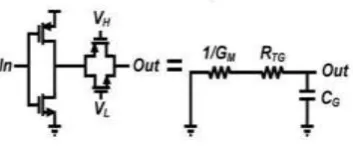
Figure 2: Schematic of ring oscillator with NAND gate.
Figure 3: RC small signal model.
Oscillator frequencies are controlled by adjusting the resistance of transmission gate (RTG)
with voltages (VH and VL) from the previous stage Using RC model the delay of each stage
cab be expressed as[7]
Where gM is the transconductance of single inverter and CG is the total gate capacitance of
stage (including both NMOS and PMOS). It can be seen that for gMRTG 1, each stage delay
will be determined by RTG, rendering inverter delay temperature dependence negligible.
Effective resistance of RTG is an average value of VTG/ ITG during transition, where VTG and
ITG are voltage and current across a transmission gate, respectively. Given a step response of
a rising input and VDD/2 as a switching point, ITG will be main same during transition as Vds
(=VDD/2) is kept above 3VT. In this case, effective resistance for a falling transition can be
Dhattarwal et al. World Journal of Engineering Research and Technology
Similar discussion also holds for a rising transition. From (1) and (2), the oscillation
frequency Fosc of an N-stage oscillator can be expressed as:
Therefore, the time delay of an individual inverter decreases as the temperature increases,
consequently as the temperature increases, the frequency of the ring oscillator increases.
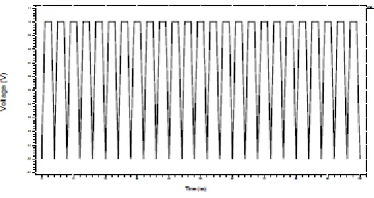
Figure 4: Output waveform of voltage controlled ring oscillator.
The schematic of ring oscillator appeared in fig 2. The oscillator is made out of transmission
gate and to reduce static power utilization, the main stage utilizes a NAND gate to prevent
the unnecessary oscillation. All components of ring oscillator are intended to work at supply
voltage of 1V. Because of the temperature dependence of threshold voltage, the oscillator
works in sub-threshold, near sub –threshold or above threshold region as the temperature
increments. Consequently, the output frequency of ring oscillator has a wide dynamic
range.[11]
Table I: Comparison of Different Voltage Controlled Ring Oscillator in Terms of Supply Voltage, Frequency Power Consumption.
[13] Design 1
Supply voltage 0.7V 0.8V 0.9V 1.0V
frequency 338.98khz 833.33khz 900.33khz 927.23khz Power dissipation 23.83 µW 53.12 µW 87.71 µW 130.67 µW
[15] Design 2
Supply voltage 0.7 0.8 0.9 1.0
frequency 500khz 600khz 800khz 1000khz
Power dissipation 66.27µW 48.13 µW 22.16 µW 0.163mW
[14] Design 3
Supply voltage 0.7 0.8 0.9 1.0
frequency 4Hz 174Mhz 216Mhz 256Mhz
Dhattarwal et al. World Journal of Engineering Research and Technology
The input voltage is fluctuated from 0.7 to 1V, in step of 0.1V and the time period at different
value of voltages from the waveform (Fig.4) can be acquired. After that Frequency is
computed by taking inverse of the time period. Table I indicates control utilization and
frequencies for various estimations of voltages.
3. Frequency Divider and Mux
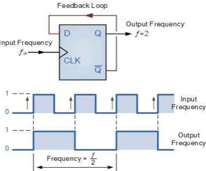
Another useful feature of the D-type Flip-Flop is as a binary divider, for Frequency Division
or as a “divide-by-2” counter. Here the inverted output terminal Q (NOT-Q) is connected
directly back to the Data input terminal D giving the device “feedback” as shown in Figure 5.
Figure 5: Block diagram of divided by 2.
Using master slave D flip – flop we implemented the divide by 2, 4 and 8 prescaler. And mux
is also implemented by using transmission gate. Throughout these techniques can reduce the
power of the circuit and improve the overall performance of the circuit.[9,10]
4. Conventional Counter
A counter circuit is normally developed of various flip-flops associated. Counters are a
broadly utilized segment in computerized circuits, and are produced as particular coordinated
Dhattarwal et al. World Journal of Engineering Research and Technology
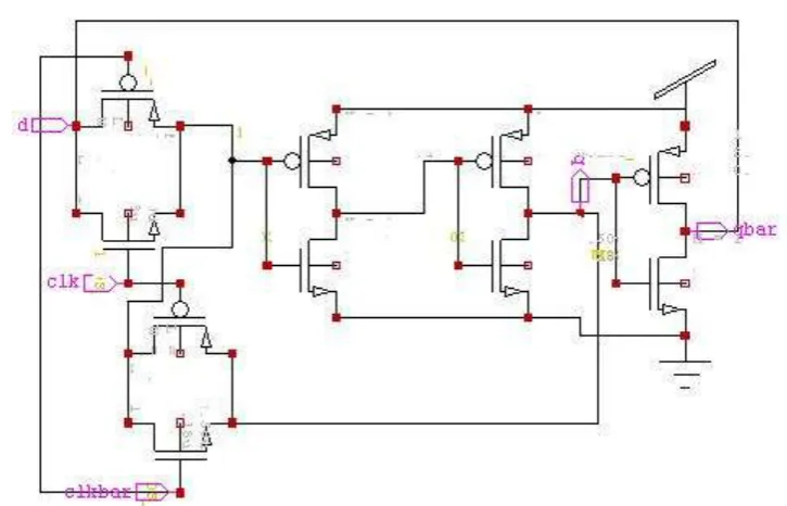
5. Conventional CMOS Implementation of D – flip flop 1-bit counter
Figure 7: Schematic conventional CMOS D flip flop 1- bit counter.
6. Proposed Counter
In this paper we proposed a 1- bit counter using different D- flip flop like ETSP based, TSPC
based and IETSP based D flip flops , Among all these design we get the TSPC D –flip flop
based counter gives the better result.
An improved counter approach is utilized here rather than the regularly utilized complex
devastation channel strategies. This approach is fitting for applications that have low
examining rate of the temperature. The outline accomplishes one degree precision over the
range 0°C to 85°C which is appropriate for generally applications. Utilizing such approach
save power and area.
Dhattarwal et al. World Journal of Engineering Research and Technology
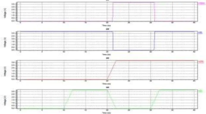
Figure 9: waveform of TSPC D- flip flop 1- bit counter.
Table II: Comparison table of conventional and proposed d flip flop 1- bit counter of power dissipation & delay at different voltage.
Design parameter Conventional CMOS D-flip flop ETSPC D- flip flop Masterslave D
-flip flop
Improved ETSPC D-
flip flop
Proposed TSPC D flip –
flop
Process(um) 180 180 180 180 180
Supply 1.0 0.9V 1.0V 0.7V 1.0V
voltage
Power 0.12mW 0.15Mw 0.87mW 37.25µW 7.9µW
Consumption
Delay(ns) 90.45 90.43 90.01 89.78 84.45
Transistor 10 8 10 9 11
count
The input voltage is varied from 0.7 to 1V, in steps of 0.1V and then time period at different
values of voltages from the waveform (Fig.9) can be obtained. After that frequency is
calculated by taking inverse of the time period. Table II shows the 1- bit counter using
different D flip flops power consumption and time delay for different values of voltages.
In this paper, mainly we work on counter using different D flip flop. We found that the
conventional CMOS D- flip flop using 1 - bit counter consume more power as compare to
TSPC D- flip flop.
We obtain a digital output code a 10- bit digital counter based temperature sensor, which use
Dhattarwal et al. World Journal of Engineering Research and Technology
division values of 2, 4 and 8 is followed by the digital counter for robust operation and
ensures functionality.[12]
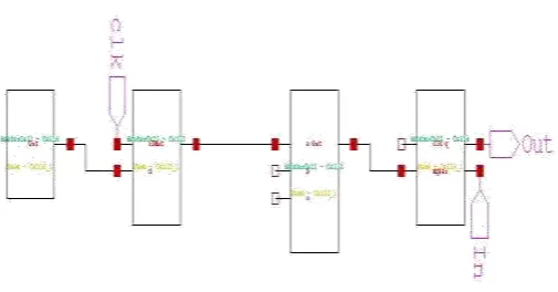
Figure 10: Schematic of proposed temperature sensor.
Fig.10 is the schematic view of proposed temperature sensor and Fig.11 shows the
Temperature variation with respect to Oscillation Frequency.
Figure 11: Temperature Characteristic of Ring Oscillator showing Frequency of Oscillation Linear to Temperature.
7. CONCLUSION
A Low power counter based -CMOS temperature sensor has been displayed. This paper’s aim
is to reduce the power of counter and improve the overall performance of temperature sensor.
For low power task, the ring oscillator is intended to be powered at voltage of 0.7-1V. With a
specific end goal to deal with process variety, the frequency of the oscillator can be carefully
trimmed. At last, since the temperature sensor exploits the temperature dependence of the
edge voltage. Ring oscillators are essential building block of complex intergraded circuits.
Dhattarwal et al. World Journal of Engineering Research and Technology
sensor has full range voltage controllability along with a wide tuning range and is most
reasonable for low-voltage and low power consumption.
REFERENCES
1. X. Zhao, B. Jin, S. Yu, and Z. Long, "Composite subscription and matching algorithm for
RFID applications," in IEEE International Conference on Advanced Information Networking andApplications, 2008; 122-129.
2. M. K. Law, A. Bermak, and H. C. Luong, “A sub- W embedded CMOS temperature
sensor for RFID food monitoring application,” IEEE J. Solid-State Circuits, Jun. 2010;
45(6): 1246–1255.
3. M. K. Law and A. Bermak, “A 405-nW CMOS temperature sensor based on linear MOS
operation,” IEEE Trans. Circuits Syst. II, Dec. 2009; 56(12): 894–895.
4. A. Vaz, A. Ubarretxena, I. Zalbide, D. Pardo, and H. Solar, “A full passive UHF tag with
a temperature sensor suitable for human body temperature monitoring,” IEEE Trans. Circuits Syst.II, Jan. 2012; 57(2): 95–99.
5. S. Zhou and N. Wu, “A novel ultra-low power temperature sensor for UHF RFID tag
chip,” in IEEE Proc. Asian Solid-State Circuits Conf.(A-SSCC), Nov. 2007; 464–467.
6. Z. Shenghua and W. Nanjian, "A nobel ultra-low power temperature sensor for UHF
RFID tag chip," in IEEE Asian Solid-State Circuits Conference, 2007; 464-467.
7. N. Retdian, S. Takagi, and N. Fujii, “Voltage controlled ring oscillator with wide tuning
range and fast voltage swing,” in IEEE Asia-Pacific Conf. ASIC, Aug. 2002; 201–204.
8. N. H. E. Weste and D. M. Harris, CMOS VLSI Design: A Circuits and Systems Perspective. Boston, MA, USA: Pearson/Addison-Wesley, 2011; 4: 154–155.
9. Kunwar Singh, Satish Chandra Tiwari and Maneesha Gupta,: “A Modified
Implementation of Tristate Inverter Based Static Master-Slave Flip-Flop with Improved
Power-Delay-Area Product”, Hindawi publishing Corporation, The Scientific World Journal, February 2014; 2014(3): Article ID 453675.
10.H.J. Wei, C. Meng, Y.C .Lin and G.W.Huang, “A 9- GHz dual modulus0.18-µm CMOS
prescaler using HLO-FF technique,” Asia Pacific Microwave Conference (APMC), Macau, Dubai, 2008; 1-4.
11.Kunwar Singh, Satish Chandra Tiwari and Maneesha Gupta,: “State-of-the-Art Master
Dhattarwal et al. World Journal of Engineering Research and Technology
12.Z. Shenghua and W. Nanjian, ‚A novel ultra-low power temperature sensor for UHF
RFID tag chip, ‛in IEEE Asian SolidState Circuits Conference, 2007; 464–467.
13.Gupta, N., “Voltage-controlled ring oscillator for low phase noise application”.
International Journal of Computer Applications, 2011; 14(5): 23-27.
14.Sheu, Meng-Lieh, Ta-Wei Lin, and Wei-Hung Hsu. "Wide frequency range voltage
controlled ring oscillators based on transmission gates”. Circuits and Systems, 2005.
ISCAS 2005. IEEE International Symposium on. IEEE, 2005.
15.Antonio corres- Matamoros, Esteban Martinez- Guerrero, and Jose’ E. Rayas – Sanchez.
“A programmable CMOS voltage controlled ring oscillator for radio frequency diathermy