Sidegn Aspects of Microhydro
Sunil Kumar1, Astha Dixit*2, Dasrath Kumar#3 #
Assitant Professor& Department of Electrical& maharishi university of information technology,lucknow(up),india-22013
Abstract — The purpose of this thesis is to first conduct a literature review regarding the technical specifications and design parameters required to design a working Micro Hydro Power System MHS (Micro Hydropower System). After review of the theory and principles of Micro Hydro System design; these principles are applied to the real case of Lamaya Khola Micro Hydro Project in Pangrang Village Development Committee (VDC) of Nepal. The field data required to design the civil components of the micro hydro project were derived from secondary data sources such as the study conducted by the village development committee as well as other independent project surveys. The micro hydro designed in this thesis was of "run-of-the river" type. Similarly, system components designed in this thesis are intake structure, headrace canal to divert the water from the source, for eBay tank, sedimentation basin and the penstock assembly. Owing to the complexity and lengthy process of designing all of the system components; only these specific civil structures are designed in this study. Design of other powerhouse and distribution components is beyond the scope of this study and so are merely selected based on the design criteria from the literature. Despite these shortcomings, the system designed is plausible, applicable and principally sound in the real life case of Lamaya Khola Micro Hydro Project in Nepal. Wherever possible, the system components that are designed are also illustrated with AutoCad. The contribution of this thesis is its practical implementation of the principle of micro hydro system design in a real life situation and specific considerations in the case of Nepal, which is topographically very different from majority of the other countries
Keywords — HPP ,Kg ,KM .Kw,
MHP,MHS,PPA,VCD etc. .
I. INTRODUCTION
A. Overview of Hydropower Systems and their Classification
In a hydropower system, the energy present in water is converted into mechanical or electrical energy by the use of hydropower plant. Generic hydro power systems can be categorized in many different ways. Some of the methods of classification are based on how the electricity is generated by the plant, what kind of grid system is utilized for the distribution of
electricity, the type of load capacity and the type of storage used by the system. (Pandey, 2006)
a) Power generation capacity
Although various categorizations exist based on different locality and nationality, the generally accepted classification of hydro power plants based on the ability to generate power is provided in Table 1.
Table 1 Common Classification of Hydro Power Plants (HPP) based on capacity generation
.
Generally, hydropower plants (HPP) generating less than 100kW of electricity are termed as micro HPP; those generating 100 to 1000 kW are termed as mini HPP; those anywhere between 1 MW to 10 MW are termed as small HPP; between 10 MW to 300 MW are termed as medium HPP and those with the power generating greater than 300 to 10 MW is termed as large HPP. Although variations in definitions exist; this is the most commonly accepted definition.
b) Types of Storage
Based on the type of storage used in hydro power plants they can be classified into storage type or "run-of-the- river" type. The major difference between these types of hydro power plants is that in the former, a dam is constructed to act as reservoir of water sources and has the ability to continuously supply the water in undulating manner. However in the latter, "run-of-the river" type, it is constructed by directing the water source to the turbine and the water source may vary according to seasons. Storage type are used generally in small to large hydropower plants whereas "run-of-the river" type are more common in micro, mini and small hydro power plants . In this study, “run-of-the-river type” of micro hydro plant is designed at a later stage.
c) Types of Grid System
Based on the type of grid system, hydro power plants can be classified into local grid and extensive grid
Power Generation
Capacity (Watts)
Type of Hydro Power Plant
<100 kW Micro
100-1000 kW Mini
1MW-10 MW Small
10MW-300 MW Medium
systems (Hydraulic Energy Program et al., 2004) . In the local grid system, the electricity is generated and distributed only for the small locality, without use of any sophisticated electromechanical distribution systems. In contrast, in an extensive grid system, the electricity generated by the HPP (Hydro Power Plant) is loaded in a form of extensive grid such as the national grid system. Generally larger HPP (Hydro Power Plant) are of these types but in this study, focus is paid to the local grid sys-tem. Similarly, based on the load of the distribution system HPP (Hydro Power Plant) have been classified into base load plant and peak load plant but it is beyond the scope of this study; as the system designed in this thesis does not consider these factors.
B. General Principle of Micro Hydro Power system (MHS)
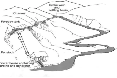
Micro hydro power plants are designed to generate electrical or mechanical power based on the demand for energy of the surrounding locality. In a typical MHS (Micro Hydro-power System) the water from the source is diverted by weir through an opening intake into a canal (Fox, 2004) . A settling basin might sometimes be used to sediment the for-11
eign particles from the water. The canal is designed along the contours of the landscape available so as to preserve the elevation of the diverted water. The water then enters the fore-bay tank and passes through the penstock pipes which are connected at a lower elevation level to the turbine. The turning shaft of the turbine is then used to operate and generate electricity (Siemens, 2004). The machinery or appliances which are energized by the hydro scheme are called the load. A typical MHS (Micro Hydropower System) layout is provided in Figure 1. The detailed description of the principal components will be given at a later stage
Figure1.1Micro Hydropower System
C. Research Description
a) Research Objectives and Questions
The objective of the study is to analyse the factors that are essential in designing a micro hydro system and to utilize this information to practically design a MHS (Micro Hydropower System) in a specific case of Nepal, which will be described in the method section. The focus of the study is in designing technical components of the MHS (Micro Hydropower System)
rather than the other factors such as the distribution of electricity after the completion of the project and other social, financial and environmental implication. Therefore the research questions could be formulated as follows:
What are the technical specifications of MHS (Micro Hydropower System)?
How can these specifications help to practically design a MHS (Micro Hydro-power System) in a real life situation?
What are the difficulties in practical implementation?
b) Research Design
Theoretical background at the beginning of the study will provide information regarding the principle that is used to generate electricity by using the water from the water source. The principle components of the MHS (Micro Hydropower System) are also described to facilitate the understanding of the system components and to explain how MHP (Micro Hydro Project) works in an interconnected manner. The technical specifications or design parameters that are required to design MHS (Micro Hydropower Sys-tem) will be also derived from literature review and explored further; because these are the most relevant information that are conducive to the design and implementation of MHS (Micro Hydropower System) in a practical context.
parameters that are very essential for the design of MHS (Micro Hydropower System) which contains such factors as measurement of head, flow of water, design discharge and so on. All of these concepts are explained while describing the method section.
1) Finally, based on the theoretical principles of MHS (Micro Hydropower System) and design parameters, coupled with onsite survey data and other calculations; a practical MHS (Micro Hydropower System) will be designed and implemented. Wherever possible, using the dimensions derived from the calculations, the components will be de-signed and shown figuratively using AutoCAD software. Lastly, the experience in system design in the specific context will lead to recommendations and implications for future system design in a similar context. The general research design or the structure of the study as described in this section are summarized
II. A. Powerhouse Components
It is at this stage that the conversion of mechanical energy of water into electrical energy takes place. Basically, powerhouse consists of electro-mechanical equipment such as turbines, generator and drive systems which will be explored further in the following sections
Turbine
In a MHS (Micro Hydropower System) hydraulic turbine is the primary component which converts the energy of the flowing water into mechanical energy through the rotation of the runner. The choice of particular turbine depends up-on technical parameters such as design head and discharge at which the turbine is to operate as well as other practical considerations such as the availability and cost of maintenance personnel. The optimum speed of the turbine is the particular speed of its rotor at which the turbine performs its best. The turbine needs to operate at this optimum speed in order to get maximum possible output at all loading conditions. Based on its functionality, turbines have been generally differentiated into two groups: impulse turbine and reaction turbine.
Generators
Although this study is not overly concerned with the selection, and uses of generators in the MHS (Micro Hydropower System) it is, however, relevant to de-scribe the basic types of generators and how they are integrated in the MHS (Micro Hydropower System). There are basically two types of generators in use for hydroelectricity generation; either synchronous or induction generators. Synchronous generators are the primary types of generators which
are used extensively in large scale power generation. When the power output levels are generally low (less than10 MW), induction generators are extensively used. Induction generators are also the preferred type of generators in MHP (Micro Hydro Project) because they can operate at variable speeds with constant frequency, are available cheaply and require less maintenance than the synchronous generator both of these generators have the possibility to be used connected to the grid or just standalone operation.
Drive systems
The main purpose of the drive systems is to transmit the power from turbine to the generators at a stable voltage and frequency at a required direction and re-quired speed. Like any normal drive systems, in a MHS (Micro Hydropower System) also, drive systems comprise of generator shaft, turbine shaft, bearings, couplings, gearboxes and belts and pulleys. The different types of drive systems common in MHS (Micro Hydropower System) are direct
drive,
“V” or wedge belts and pulleys, timing belt
and sprocket pulley and gearbox drive
systems. A direct drive system is one in
which the turbine shaft is connected directly
to the generator
shaft.
ELECTRICAL LOAD CONTROLLERS
All mhs (micro hydropower system) will have to have switchgear in order to separate the power flow when necessary and also to control the electrical power flow. There are several different kinds of switches used in an mhs (micro hy-23 droopier system) such as isolators which are manually operated, switch fuses which additionally can provide fuse for current limiting, mccb (melded case circuit breakers) which are used for protection from over current or short circuits and so on.
B. DESIGN PARAMETERS OF A MHS (MICRO HYDROPOWER SYSTEM)
a) HEAD MEASUREMENT
The head is defined as the vertical height in meters from the level where the water enters the penstock to the level where the water leaves the turbine housing. Altimeter is used to calculate the “head” during the field survey.
b) MEASURING WATER FLOW RATE
the first step in determining the hydro power potential of a water source is to measure the flow rate. it has been defined as the quantity of water flowing past a point at a given time. there are several methods available to measure water flow rate such as salt dilu-tion method, bucket method, weir method and so on. however, in mountainous region such as that of nepal salt-dilution method of determining the head is the most common one. the salt dilution method is especially appropriate in this case because most of the water source used for the mhs (micro hydropower system) is small flow stream.
C) MEASURING POTENTIAL POWER AND ENERGY
According to the Bernoulli energy equation, (Fox, 2004) energy in water is stored in terms of pressure energy, velocity energy and elevation energy. It can be further stated as:
Power (Energy/sec) = Pressure energy/sec +
velocity energy/ sec + elevation energy/sec
OR,
P=P/ΡG +V2/G+Z
Where,
P = electrical or mechanical power produced, W
ρ = density of water, kg/m3
g = acceleration due to gravity, m/s2
z = elevation of the point above the reference point
v = velocity energy of the water
The potential power that can be generated from the micro hydro power plant is often calculated from the survey of the site (Pandey B. , 2006).The difference in the energy is converted into useable energy by the hydropower plant when there is a
difference be-tween energy of the water. Therefore
P=P/ΡG +V2/G+Z OR P= (P/ΡG+V2/2G+Z)
INTAKE -(P/ΡG + V2/2G+Z) EXIT
d) SELECTION OF TURBINES AND ITS
COMPONENTS
The parameters that help in the choice of turbine are tabulated below in table 4. It is primarily the head measurement that determines the selection of a suitable turbine for a particular MHS (Micro Hydropower System). (Hydraulic Energy Program et al., 2004). For example, in cases where the head measurement is more than 50 meters, pelton or turbo types of turbines are chosen over others. Similarly, when the head measurement is in between 10 meters and 50 meters, cross-flow, turbo or multi jet pelton types of tur-bine are preferred. In cases where the head measurement is lower than 10 meters, cross-flow turbine is preferred. The selection for reaction type of turbines is also made in a similar way, and these criteria are summarized in
TABLE 4.
Factors affecting the selection of the Turbine for MHS (Micro Hydropower System)
Head
Classification
Type of Turbine
Impulse Reaction
High (>50m) Pelton, Turgo
Medium (10-50m)
Cross flow, Turgo, Multi-jet Pelton
Francis (spiral case)
Low (<10m) Cross flow Propeller, Kaplan, Francis (Open Flume)
However, there will be some loss of power while the available water energy is converted by the hydropower plant. The actual power that can be generated from the given source of water is thus, P=ρ.g.H.Q.η ……….(1.1)
Where,
P = electrical or mechanical power produced, W ρ = density of water, kg/m3
η = overall efficiency of MHs (Micro Hydropower system)
It can be seen clearly from the equation that the power generated by the water available depends upon the flow rate of the water, elevation head (elevation difference between intake and exit of water), and gravitation force, density of water and efficiency of the hydropower system. The goal of the hydro power is to convert the available water energy into mechanical
III. METHODS
A. Description of the Case
Lamaya Khola MHP (Micro Hydro Project) project was approved by the Pangrang Vil-lage Development Committee (VDC) of Nepal on May 2010, after a detailed feasibility research taking into account all the relevant technical, economic and social factors. The project gets its name from Lamaya Khola River, the water source for the MHP (Micro Hydro Project), which is a perennial source of water with sufficient discharge also in the dry season. Pangrang VDC lies in the western part of Nepal, in the mountainous re-gions where the elevation of the proposed site for the MHP (Micro Hydro Project) is above 1300 mean sea level.
Before discussing the design of primary components of the MHP (Micro Hydro Pro-ject), it is necessary first to discuss the preliminary data available through the feasibility survey. The survey team appointed by Pangrang Village Development Committee made detailed engineering survey at around summer of 2010. Detailed measurements were carried out to locate the best position for intake, headrace canal, forebay, power-house, tailrace and the spillway. Some of the important parameters that were measured were published by Pangrang VDC and have been used in this study as secondary source of data. Some of those important survey parameters are discussed in this section.
The report published by Pangrang V.D.C. on Lamaya Khola River shows that the flow of water measured on 12th of May, 2010 was 0.204 m3/s. However, as the report ex-plains, design discharge was taken to be 0.154 m3/s, after considering that 15% of the calculated lowest flow downstream releases due to environmental reasons and 10% of the discharge were lost through evaporation or seepage. The survey team used salt dilu-tion method to calculate the water flow and to derive the design discharge from this da-ta. The detailed results of the mean monthly flow of Lamaya Khola River, is shown in Table 5
Table 5: Mean Monthly Flow of Lamaya Khola River (Pangrang Village Development Committee, 2010
Month Flow at River, Liter/
Second
January 535.44
February 402.69
March 300.91
April 221.26
May 201.34
June 604.34
July 2480.30
August 3084.34
September 2212.58
October 1442.60
November 1006.72
December 736.79
Annual Average 1102.42
Pangrang VDC also conducted the survey about the energy consumption pattern in Pan-grang VDC and the estimated demand for electricity, so as to determine the power out-put of the MHP (Micro Hydro Project), which would be able to satisfy this demand. The detailed of the energy consumption pattern are quite much in detail but the part of the energy consumption pattern which shows the estimated power demand to be 25 kW is given in Appendix .
Design of the forebay tank
The forebay tank is similar to the settling basin except that the outlet transition is re-placed by a trash rack and the forebay tank has an opening to penstock pipes. The most important element to be calculated in the design of the forebay tank is the submergence 55
head. The submergence head or the depth of water above penstock pipe, should fulfill the criteria (Submergence head) hs1.5 V2/2g (6.1)
Where, V refers to the velocity of water in the penstock, which in this case is 2.5 m/s;
hs 0.48 m
In other words, the submergence head of the forebay tank should be 0.48 meters.
Similarly while designing the forebay tank it is also necessary to construct the diameter of the air vent or dairvent which is given as,
d2airvent = Q [(F/E) (D / effective) 3] (6.2) Where,
d2airvent = internal diameter of air vent in mm It is already known from the survey that the maximum flow of water through turbine is 0.154 m3/s, “E” is the Young’s modulus for the penstock material, D is the diameter of the penstock and “F” is the safety factor. In this case, it has been chosen as 10 because our design consists of exposed pipes. Therefore,
d2airvent = 154 [(10/210000) (280/ 2.78)3]
= 32.77 mm. The diameter of the air vent to be
constructed is therefore 32 mm.
3.3.7 Selection of Turbine and basic design of other powerhouse compo-nents
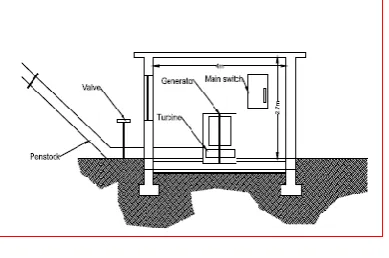
Since, the gross head of the MHS (Micro Hydropower System) is 30 m and the design discharge is 0.1554 m3/s, the appropriate turbine for this situation proposed is pelton flow turbine, with efficiency of 70-75% and rated capacity of more than 25 kW (most probably 38 kW). Similarly, the basic dimensions of the powerhouse were already cal-culated in the preliminary survey. Based on these dimensions, the design of physical powerhouse in autoCAD is given in figure 17.
FIGURE 17: DESIGN OF POWERHOUSE COMPONENTS FROM AUTOCAD
IV. RESULTS
Based on the field survey data, the study dealt with designing the major civil compo-nents for the Lamaya Micro Hydro project in Pangrang Village Development Commit-tee Nepal. Based on the design parameters, the calculations carried out helped to de-termine critical dimensions of the civil components of the Lamaya Khola Micro Hydro Project. The critical dimensions of various components are summarized in Table 7.
Table 7: Summary of the critical dimensions of civil components of Lamaya Khola MHP (Micro Hydro Project
)
Components Critical Dimensions
Dimensions of Orifice for side Intake
Design flood level = 1.4 m
Area of Orifice = 0.12 m2
Delivery discharge = 0.174 m3/s Or 174 l/s Flood discharge = 302.55 l/s
Dimensions of
Headrace Canal
Cross sectional area = 0.171 m2
Optimum Canal Height = 0.314 m
Canal bed width = 0.387 m
Canal top width = 0.7 m
Critical Velocity = 1.55 m/s
Wetted Perimeter = 1.08 m
Head Loss = 2.86 m
Hydraulic Radius = 0.161 m
Canal Bed Slope = 0.0028 (1: 374m) Size of largest particle = 4.74 mm
Dimensions of Settling Basin
Length = 6.84 m
Expected silt load = 3326.4 kg
Volume of Silt Load = 2.55 m3
Average collection depth = 0.26 m
Spillway Length = 6 m
Dimensions of
penstock assembly
Material = Mild steel pipe 280 mm MS ID Length = 70 m
Pipe diameter = 260 mm
Total head loss = 0.722 m
Forebay Submergence head >0.48 Diameter of air vent = 32.77 mm
V. CONCLUSIONS
only civil work components which comprised of the side intake, headrace canal, forebay, sedimentation tank, and spillway and penstock assembly. However, the thesis would have gone be-yond its limitation in scope and length if the design parameters and design process for other civil components such as the physical powerhouse have been added. In addition to civil components, a MHP (Micro Hydro Project) also consists of powerhouse compo-nents such as generator, turbine and so on and other components related to electrical distribution. These were not included in this thesis
Similarly, the practical design of various components that were conducted in this thesis also led to the realization that the design of the system components is very much deter-mined by the location specific factors. From the very beginning, the MHP (Micro Hy-dro Project) designed was constrained to being “run of the river” type, because the river source, Lamaya Khola, is situated in a mountainous topographical region. Similarly, in the design of spillway, headrace canal and forebay tank, the choice of materials were already determined by their availability and local topographical conditions. For exam-ple, the choice of stone masonry with cement mortar type of canal for the headrace was considered because in the topographically hilly reason, mud mortar type, for example would have led to seepage of water from the canal and so would have caused landslide in the longer run which is not considered desirable. Similarly, the choice of mild steel for the penstock and the type of turbine selected were also
largely selected based on the norm of the region. Altogether the study showed that construction of MHP (Micro Hy-dro Project) was feasible in the project site and there were no major problems apparent at least at the design stage of the micro hydro project.
REFERENCES
[1] Bhattarai, D. N. (2005). Hydropower Development in Nepal: A study of Demand for Electricity and Financial Requirement up to 2030. Devi Kumari Bhattarai.
[2] BPC Hydroconsult. (2006). Civil works guidelines for micro-hydropower in Nepal.
[3] Chitrakar, P. (2004). Micro-Hydropower Design Aids Manual. Kathmandu: Small Hydropower Promotion Project (SHPP/GTZ) and Mini-Grid Support Prorgramme (MGSP/AEPC-ESAP).
[4] Davis, S. (2003). Microhydro: Clean Power from Water. New Society Publishers.
[5] Davis, S. (20210). Serious Microhydro: Water Power Solutions from the Experts . New Society Publishers. [6] ENTEC AG. (March 2001). Evaluation of Small Hydro
Projects in Namche Bazaar (Nepal) and Rangjung (Bhutan). St. Gallen, Switzerland: Austrian Development Co-operation. [7] Fennell, M. (2011). Hydropower: Basic Concepts (The
Science of Electricity). Mark Fennell.
[8] Fox, R. W. ;McDonald, A. T. ;& Pritchard, P. J. (2004). Introduction to Fluid Mechanics: Sixth Edition. John Wiley and Sons, Inc.
[9] Greacen, C. E. (2004). The Marginalization of “Small is Beautiful”: Micro-hydroelectricity, Common Property, and the Politics of Rural Electricity Provision in Thailand. Berkeley: University of California.