(Received 22 December 2010/Accepted 20 April 2011)
When we design and construct a large-scale device, it is very important to confirm the interference among its parts. We might need to confirm not only the interference among the parts that are designed at the start but also the interference with some parts that are added after construction. However, sometimes even on using 3D CAD, we cannot detect the interference or the collision among parts, particularly when these parts form a complex 3D shape. On the other hand, virtual reality devices have been used in various fields such as design support systems; however, real-time collision detection among complex parts has been difficult to achieve. We constructed a system that can detect collision and interference in real time in a virtual reality system. This engine can detect interference between polygons. This enables to calculate more accurately than voxel-based detection engine. Moreover, we propose a dynamic interference vector for removing interference. This vector is defined as a local minimum vector which removes the interference from the same edge where the contact starts. This method enables to prevent an object moves discontinuously, when the interference is removed. Finally, we introduced an example of using this system for assembling parts.
c
2011 The Japan Society of Plasma Science and Nuclear Fusion Research
Keywords: design aid, assembly, augmented reality, haptic interface, collision detection, visualization DOI: 10.1585/pfr.6.2406061
1. Introduction
Immersive virtual reality (VR) systems, such as CAVE [1], have been installed and used in various fields. A feature of these systems is that the user can intuitively grasp 3D shapes and phenomena in the environment. De-signing systems is one of the practical uses of this device. Many 3D computer-aided design (CAD) software pack-ages are used for designing structures, because they are very effective in creating 3D models for design. However, these environments are not fully intuitive, because the user cannot observe a 3D model with stereoscopic view and touch the objects. The purpose of this study is to create an intuitive design environment with stereoscopic view and haptic sense (force feedback).
In general, there are two main purposes for using a VR system in design. One purpose is to use it instead of 3D CAD. The user directly draws lines and creates a 3D object in a virtual environment. In fact, many researches have been performed in this regard [2, 3]; however, it is difficult to design in an immersive VR system, because the user must design in the standing position and keep his/her arms in the air. The other purpose is to use it for assem-bling parts. When it is used only for assemassem-bling, it is easy for the users to keep their hands in the air. Researches on author’s e-mail: [email protected]
∗)This article is based on the presentation at the 20th International Toki
Conference (ITC20).
the assembly of parts, especially in an immersive virtual space have not been carried out as often. For example, the research studies of [4] and others simulate the assem-bly process. However, these systems only simulate the as-sembly process of a very simple and small structure. It is impossible to simulate accurate behavior without accurate interference simulation. Although some 3D CAD software packages have such interference functions, these functions cannot operate in real time. On the other hand, operating in real time is an indispensable function of VR systems. Therefore, this study aims to build a virtual assembly sys-tem with collision and interference detection functions that operate in real time.
Moreover, to construct an assembly assist system, it is also important to add a haptic sense. We have already constructed a system with the above-mentioned virtual as-sembly system; however, it is not intuitive. This is because when objects contact each other, the contacted object only flashes red [5]. Thus, we append haptic information to this system. By using haptic sense, we can directly feel the contact and intuitively know the amount and direction of the force.
2. System Configuration
Our system consists of drawing a stereoscopic image, rendering haptic information, and calculating the
interfer-c
2011 The Japan Society of Plasma
Fig. 1 PHANTOM Omnir.
ence between objects. Interference detection is expensive, and this influences the rate of graphics in VR if all of the calculations are performed on one computer. Therefore, it is necessary to use multiple computers. Our proposed system consists of two computers: one for the virtual envi-ronment including a haptic device control, and the other for calculating interference. These computers are connected to LAN; however, because the amount of data transferred is significantly small, it is not necessary to use a high-speed network.
2.1
Haptic device
We use a haptic device for controlling virtual objects. In our previous work [5], we only used a 3D mouse to move objects. By using a haptic device, we can get im-mersed to a greater extent in the virtual environment more and intuitively control virtual objects. In this study, we use a PHANTOM Omnir [6] (Fig. 1) as a haptic device. The PHANTOM can provide force feedback to the user with a stylus interface. Using this stylus, the user pokes the vir-tual objects. The PHANTOM Omni has three degrees of freedom. The position and posture of the stylus are auto-matically transformed to the PHANTOM coordinate sys-tem by a library. The maximum output force is 3.3 N, and the continuous output force is 0.88 N. In order to output suitable force to the user, the magnitude and direction of the force must be provided. The method for calculating this force vector is described in Section 2.2.
The workspace of the PHANTOM is 160 mm wide, 120 mm high and 70 mm deep. In general, when we use PHANTOM, its workspace is mapped to the entire vir-tual space. However, in this study, we use an immersive VR system [7] and the system measures approximately 3.6×4.1×2.8 m (maximum). It is unnatural to map the workspace of the PHANTOM to the entire virtual space, because the virtual space is physically considerably larger than the workspace of the PHANTOM. Therefore, we map a part of the virtual space to the PHANTOM workspace, and the workspace can be moved in the virtual space (Fig. 2). To use this function, we append a magnetic sensor (Polhemus Patriot) to the PHANTOM, which enables us to detect its position and posture in the virtual space. The coordinate system of the PHANTOM workspace is
trans-Fig. 2 Relationship between view volume of VR space and PHANTOM workspace.
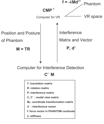
Fig. 3 Data flow.
formed by moving the PHANTOM itself.
2.2
Data flow
Figure 3 shows the data flow between the computers. When the user operates an object with the PHANTOM in the VR space, translation and rotation information is trans-formed from the PHANTOM coordinate system to the VR space coordinate system (Fig. 2). Then, this information is sent to the computer for interference detection in the form of a 4 model view matrix. This model view matrix is 4 ×4 and consists of transformation and rotation matrix. If the objects interfere, the model view matrix and the vector mentioned in section 3 that removes the interference are sent back to the computer for VR. Finally this matrix is applied to a present scene and the caused interference is removed. Moreover, the suitable force vector is calculated from the interference vectord’and the virtual stiffnessk. In this study, we only deal with rigid objects; however we set a virtual stiffness for providing force information to the user.
Many researches dealing with the collision and inter-ference detection have been proposed, especially in the fields where real-time collision and interference detection technology is highly required, such as the game production field. In one such proposed method, a 3D model is con-verted into a voxel data form, which covers the entire 3D model and searches the interference among these voxels. Following are the advantages of this method: it is a very simple algorism, easy to calculate, and rapid; however, this method cannot detect highly accurate interference. On the other hand, various algorisms, which can detect the inter-ference among complex objects, have been recently pro-posed [8, 9]. However, either these methods cannot detect interference among convex objects; therefore the concave-shaped objects are divided into convex-concave-shaped objects and calculated as multiple convex objects. These algorisms also cannot obtain a strict solution; neither can they esti-mate the manner in which these objects interfere (length of penetration). To solve such a problem, we constructed a VR system with an interference detection engine, called SmartCollision, which can detect interference among poly-gons. This algorism can calculate interference more accu-rately; on the other hand, the calculation speed is slower than that of a voxel-based detection algorism. Accuracy is indispensable for simulating a design in virtual reality; therefore, we adopt this algorism.
3.1
Determination of interference vector
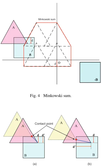
The penetration depth is calculated by the Minkowski sum [10]. Figure 4 shows an example of the interference. The Minkowski sum between A and B is given by the fol-lowing function.A⊕ −B={p+q|p∈A,q∈ −B}. (1) This equation calculates difference of all points between object A and B. Therefore, if the origin is inside the ob-ject obtained from this function, obob-jects A and B are inter-fered, and if the origin is on the edge of this object, object A contacts object B. On the other hand, if the origin is out-side, these objects are not interfered. By using this method, we can detect interference and the minimum interference vector for canceling the interference is easily calculated (Fig. 4).
3.2
Dynamic interference vector
Figure 5 shows the concept of a dynamic interference
Fig. 4 Minkowski sum.
Fig. 5 Dynamic interference vector. d is the minimum vector for removing penetration andd’is the dynamic interfer-ence vector: (a) Object A penetrates from the top edge of object B (b) Object A penetrates from the side edge of object B.
vector. The dotted triangle object A moves to the posi-tion of the solid line triangle, and penetrates object B. Fig-ure 5 (a) indicates the case where object A penetrates from the top of object B. In this case, the minimum interference vector isd, and by moving object A in the opposite direc-tion of this vector, we can remove this interference. On the other hand, in the case of Fig. 5 (b), the minimum vectord
is the same as that in the case of Fig. 5 (a). The difference is that object A penetrates from the side of object B. In this case, if we move object A in the opposite direction of the minimum vectord, object A penetrates from the side of ob-ject B and stands apart from the top side of obob-ject B. The observer feels that object A suddenly moves from the side to the top of object B. Then, we introduced the concept of a dynamic interference vector. In this concept, the dynamic interference vector is determined as a vector for removing the interference from the edge where the contact starts. By using this concept, the interference vector is defined byd’
Fig. 6 Virtual reality system [7] and experimental environment.
4. Application Example
An application example of a nuclear-fusion-reactor design is described in this section. A nuclear fusion re-actor consists of numerous parts having a complex, curved surface shape, and the construction period is 10 years or more; hence, the numerous parts and devices will be added after the initial design is complete. Therefore, it is diffi -cult to sustain consistency among the parts, although it is very important to maintain this device. The present pro-cedure of introducing new parts (or equipment) to the de-vice is as follows. The first step is to create the model of the parts in 3D CAD and to create a real 3D model based on the 3D CAD model. By using this model, consistency is manually confirmed. However, it takes a considerable amount of time to make a real 3D model, and it is diffi -cult to frequently change the shape of parts and to examine many types of parts. If this procedure can be performed in a virtual space, the time for constructing and estimat-ing the nuclear fusion reactor will be dramatically reduced. Moreover, if we can estimate the optimal size of the parts introduced to the device or can optimize the sequence to assemble the parts, we can also reduce the amount of time required for the construction or improvement of the nuclear fusion reactor.
We used two computers; one computer equipped with Intel Xeon CPU W3520 2.67 GHz and 4 GB RAM for the interference calculation and other computer equipped with Intel Core2Duo E8200 2.67 GHz and 2 GB RAM and a Geforce Quadro FX 4800 for the virtual environment. Fig-ure 6 shows the VR system in this study.
Figure 7 shows an example of applying this system. The operation object is the object drawn at the center of this figure, and this part is inserted in the nuclear fusion re-actor and assembled into the device. The top figure shows the object that does not contact the device. In this case, the controlled object is colored green and the haptic device provides no information. The bottom figure shows the ob-ject that contacts the device, and is colored red; the haptic device provides force information to the user as mentioned above.
We estimated one example: the controlled part con-sists of 709 vertices and 1,479 polygons, and the static model consists of 16,239 vertices and 30,930 polygons. As
Fig. 7 Example of collision detection.
a result of the estimation, the process speed is above 60 Hz. Moreover, if the size of the controlled parts is changed, the calculation speed does not change to a great extent.
5. Conclusion
In this study, we proposed a design aid system, in par-ticular an assembly support system in an immersive VR system. This system enables us to provide haptic infor-mation to the user by using the PHANTOM haptic de-vice. This haptic device promotes immersion and enables the user to intuitively control virtual objects. In order to provide suitable force feedback to the PHANTOM, this system has a function that can detect interference among both convex and concave objects. This interference detec-tion engine is sufficiently fast and accurate for utilizing this system in a real design field. Moreover, we explain the ap-plication to a nuclear fusion reactor in which the speed of interference detection is above 60 Hz. This speed is con-siderably faster than the refresh rate of images. It can be concluded that this system enables us to simulate the as-sembly of parts in an immersive VR system in real time, and to improve the design process.
Acknowledgment
This study was partly funded by a Grant-in-Aid for Scientific Research KAKENHI (22500114).
[1] C. Cruz-Neira, D.J. Sandin and T.A. DeFanti, Proc. SIG-GRAPH ’93 (1993).
![Fig. 6Virtual reality system [7] and experimental environment.](https://thumb-us.123doks.com/thumbv2/123dok_us/8443510.1702297/4.595.356.500.203.317/fig-virtual-reality-system-and-experimental-environment.webp)
