REQUIREMENTS EVOLUTION AND REUSE USING THE SYSTEMS ENGINEERING PROCESS ACTIVITIES (SEPA)
K. Suzanne Barber, Thomas J. Graser, Paul S. Grisham, Stephen R. Jemigan The Laboratory for Intelligent Processes and Systems
The University of Texas at Austin Austin, TX 78712
voice: 512-471-6152 fax: 512-471-3316 [email protected]
ABSTRACT
As more organizations attempt to reuse previous development efforts and incorporate legacy systems, typical software development activities have transitioned from unique ground-up coding efforts to the integration of new code, legacy code, and COTS implementations. This transition has brought on a whole new set of development issues, including resolving mismatches between integrated components and tracing legacy and COTS components to requirements. This paper presents the Systems Engineering Process Activities (SEPA) methodology, developed to address these and other issues in current software development practices. SEPA aids the reuse and integration process by focusing on requirements integration and evolution, while maintaining traceability to requirements gathered from domain experts and end users. The SEPA methodology supports the development process by promoting requirements analysis prior to design, separation of domain-based and application-based (i.e. implementation-specific) requirements, and evaluating system component suitability in terms of domain and application requirements. The paper also presents an example illustrating the application of SEPA in the emergency incident response domain to facilitate requirements management and foster requirements reuse.2
INTRODUCTION
Despite the introduction of software development methodologies and CASE tools to help alleviate the "Software Crisis," the development and maintenance of software is still too expensive and error prone. Effective reuse from previous software development efforts has the potential for increasing software productivity and quality an order of magnitude (Caldieri, Gianluigi, & Basili, 1991). However, current methodologies do not emphasize the reuse of artifacts other than code (analysis or design) from previous implementations. While code reuse typically occurs only at lower-level system design artifacts, analysis and design reuse often results in whole collections of related artifacts being reused (Department of Defense, 1996). Methodologies can further increase odds for reuse by identifying potential reuse at all system levels (e.g. system, component, code function) and among all participating elements (e.g. new development, legacy systems, and commercial off the shelf (COTS) components).
Reuse of requirements provides a number of benefits, including the following:
1. motivation for selection of components: Requirements guide the selection of optimal components for reuse. When requirements are transferred between development efforts, the rationale behind the original component selection decision is made available to the system designer.
2. context for reuse decisions: Requirements trace back to information gathered from domain experts and system users. Requirement-based reuse decisions are set in the context of domain processes or specific implementation needs.
3. parametric constraints: Requirements come in many forms, including parametric constraints (i.e. the system delivered must run at speed x) as well as general guidelines (e.g. the system's interface should be user friendly) and domain tasks and processes. Parametric constraints allow a static evaluation to narrow the field of available components.
The leveraging of legacy systems that were not designed with reuse in mind comprises a large part of the reuse motivation. However, the reusability of old systems is often difficult to evaluate by direct inspection. Perhaps the rework effort can be determined through code evaluation and system documentation. However, it can be difficult to determine the relative adherence of the old implementation to newly gathered requirements. When originally under development, requirements were likely gathered and analyzed for satisfaction by the old implementation. Given that a requirements effort has already occurred, an alternative is to determine which of the old requirements can transfer to satisfy new requirements rather than take on a fresh evaluation of the old system.
Section 0 provides a model of requirements evolution and a list of features which are strongly desired in a methodology intending to support requirements evolution and reuse. Section 0 introduces the System Engineering Process Activities (SEPA) methodology and positions its distinguishing characteristics among these features. Section 0 provides an example illustrating the application of SEPA in the incident response domain.3 Section 0 concludes with a discussion highlighting selected SEPA contributions to requirements evolution and reuse evident in the example.
REQUIREMENTS EVOLUTION AND NECESSARY METHODOLOGICAL FEATURES In this section, we discuss some essential features of good software engineering methodologies to support requirements evolution and reuse, with an emphasis on activities during requirements gathering and analysis. Figure 6 depicts the requirements evolution scenario and the traceability to implementations under a comprehensive development methodology. Old Requirements captured, analyzed, and verified are eventually linked to components in the implementation, Old Implementation. As New Requirements are captured, analyzed, and verified, they are mapped to Old Requirements, thereby indirectly referencing components from the Old Implementation. The mapping from New Requirements to Old Requirements may not cover the complete set of New Requirements and some of the Old Requirements may not be relevant in the New Requirements. As the Old Implementation may only partially address the New Requirements, there is a need for evolving (modifying) the Old Implementation. The remaining New Requirements spawn development of new components (New Implementation), which when integrated with components from the Old Implementation, result in a Delivered Product.
Requirements Mapping
Old Requirements
New Requirements
O;
0°
Old \^f ' •
Implementation
Traceability Links
b
NewImplementation
Integrated Components
Delivered Product
Figure 6: Requirements Evolution and Traceability
The difficulty in implementing the model in Figure 6 lies in matching requirements to implementations. To effectively render this mapping, implementations must be expressed in a meta-specification composed of the same language as the requirements themselves. Furthermore, this meta-specification should operate at an abstraction level that allows it to be independent of implementation specifics (e.g. Component A requires an integer value while Component B provides a float value), yet be expressive enough to capture a broad range of requirements (e.g. component must perform domain Task X on Operating System Y with Throughput Z). Defining this meta-specification at the appropriate level of abstraction along with careful management of Traceability Links4 from requirements to implementations will encourage the reuse of whole collections of related artifacts from analysis and design.
Given the requirements evolution process outlined above, the development cycle becomes an issue of integration on two levels:
3 Detailed discussions of the operations of SEPA tools are beyond the scope of this paper.
1. mapping, evolving, and integrating requirements previously gathered, analyzed, and verified into new requirements and
2. integrating technologies inferred by the traceability links from integrated requirements.
Figure 7 illustrates this two-level integration problem. Requirements are derived from an array of sources: a previous development effort, available media (e.g., system documentation), multiple domain experts, and multiple system users. Requirements elicited from multiple sources often overlap and possibly contradict. Yet understanding requirements involves incorporating multiple viewpoints, involving the capture, analysis, and resolution of many ideas, perspectives, and relationships at varying levels of detail (Kotonya & Sommerville, 1997). Once integrated, requirements guide the selection of appropriate COTS components, legacy systems, and newly developed implementations. Multiple system configurations may satisfy the same set of requirements, requiring further tradeoff studies for evaluation. Resulting selections are then integrated into a cohesive solution
Two-level Integration Problem
Previous Development
Efforts
v
Requirements
h 4 fc 4 k •* k.
W ^ F ^ F -^ p-Various Media used Different Different
for Requirements Domain System Capture Experts Users
y ^
Techno
w .j »>
r ^
logy •* ^
' i
-* >
Across multiple sources
integrated requirements to technology matches
r
Various Legacy Various COTS Infrastructures Implementations Developers
Across multiple technology solutions
Figure 7: Two-level Integration Problem
Opportunities for successful reuse, as suggested by the model in Figure 6, are increased through the use of a methodology that supports the following six features.
• Traceability: Throughout the requirements lifecycle, emphasis should be placed on maintaining accurate traceability. In (Gotel & Finkelstein, 1994), Gotel reported the results of a survey of more than 100 software engineering practitioners that indicated "most of the problems attributed to poor requirements traceability were found to be due to the lack of (or inadequate) pre-requirements specification (pre-RS) traceability." Contrary to the motivation of these results, they noted that existing tools mainly supported post-RS traceability only. Moreover, Palmer notes that current tools provide little support for identifying and maintaining traceability information (Palmer, 1997). Methodologies must provide the emphasis for the development of tools that support the identification and evolution of traceability information from requirements elicitation to requirements maintenance.
• Support for Multiple Viewpoints: The recognition of 'viewpoints' in software engineering is first credited to the CORE methodology (Mullery, 1979) in the late 70s. Since that time, it has become widely accepted that a complete requirements gathering effort must seek out the individual needs of the various stakeholders that will interact with the system to be developed (Sommerville, Sawyer, & Viller, 1998). Often the requirements gathered from these 'viewpoints' will overlap and possible conflict. Compromises are made in every development process to arrive at a single set of requirements for the project. These compromises may be implicit, un-documented, and performed without the input from the original stakeholders. Methodologies that hope to enable reuse of requirements and derivative artifacts (e.g., code) must accurately identify the source of these requirements (see Traceability above). This need requires that the methodology acknowledge the existence of multiple viewpoints and guide the viewpoint reconciliation process.
• Separation between Domain and Application Requirements: To improve chances for reuse, software methodologies often suggest that "what" a system must do should be modeled independently of "how" the system should be implemented. The presumption is that "what" is done in a domain changes far less often than "how" it is accomplished, especially given frequent changes in technology (Tracz, 1991; Tracz, 1993; Tracz, 1995). Despite this advice, other requirements management tools do not explicitly recognize this separation.
• Comprehensive Process Support for Requirements Refinement and Management: Numerous requirements management tools are available for requirements analysis and refinement, taking different approaches to requirements representation (Chipware, 1999; QSS, 1998; Technologies, 1999). Even more tools support object-oriented design after requirements have already been elicited, validated, and merged (SES, 1999; Verilog, 1997). Some tool suites attempt to bridge requirements identification with subsequent object-oriented analysis and design (Rational, 1998). However, no current tools adequately support the requirements refinement process with automated support for traceability maintenance from elicitation through maintenance (Gotel & Finkelstein, 1994; Palmer, 1997). Without this integration, the transition from requirements capture, to requirements synthesis, to class derivation, to system design becomes excessively difficult. In the absence of a comprehensive process support for requirements refinement and management, some requirements may be ignored while others may not be maintained in the long-term after implementation or as the domain scope changes.
• Support for Requirements Volatility: Requirements change even during the initial development of a system. Changes may be promoted by more accurate requirements elicitation, changing user needs, changes in the relative importance of various user's requirements, and technology changes. Dobson et. al. (Dobson, Blyth, Chudge, & Sterns, 1992) note that requirements can also be driven by the downstream development process. Failure of the methodology to support changing requirements will result in requirements that are "incomplete, inconsistent with the new situation, and potentially unusable" (Christel & Kang, 1992). The prospect that requirements might be used (reused) beyond the current development effort underscores the need for the methodology to recognize and support requirements volatility throughout the project's lifecycle.
In this section, a model for requirements evolution was presented and six necessary methodological features were identified. In the following section, a methodology is proposed that emphasizes these features so that the requirement evolution and reuse model can be realized.
THE SEPA METHODOLOGY
The Systems Engineering Process Activities (SEPA) Methodology builds upon the DSSA approach (Tracz, 1991) and popular object-oriented methodologies by distinguishing between domain functional requirements and implementation-specific requirements, defining a domain architecture, identifying applicable technology solutions, and finally utilizing the domain architecture and technology solution specifications to assist reuse evaluations and design trade-off decisions. The domain architecture represents an object-oriented partitioning of domain functional and data requirements without designating a particular implementation. To realize an actual system implementation, the system designer must select appropriate technology solutions that satisfy both domain requirements and application implementation-specific requirements.
Knowlege Acquisition
Unified Knowledge
Model *^_
^ Application
Infrastructure
Requirements
^ Model (AIRM)
^ . • • • . ' . '
Infrastructure
Ref^ch.
Classes (IRACs)v ;
tfr~ • •
Registered Technology
Solutions
System Design Specifications
Knowledge Acquisition
Knowledge Modal Creation & Synthesis
PARATION
Current
Technology,
Solutions
Appli Reauire
Reqmts Derivation
System Configuration
Evaluation
Knowledge Acquisition Transcripts
Domain Model
Technology Solutions Repository
Domain Reference Architecture Classes (DRAGS)
Figure 8: The SEPA Process Funnel
The SEPA methodology encourages gathering requirements from a diverse group of stakeholders (end-users, domain experts, developers, etc.) that are representative of all the contributing perspectives. The first step in the knowledge acquisition effort is to identify the relevant viewpoints from which domain knowledge will be elicited. To support the knowledge synthesis and resolution process, the domain viewpoints should be organized hierarchically. Next, domain experts must be selected and associated with a domain viewpoint. Ideally, each Knowledge Acquisition (KA) session will be conducted with a single stakeholder, and the artifacts generated as a result of that session will reflect knowledge from a single domain viewpoint.
The preferred approach to knowledge acquisition is to elicit information in the context of scenarios of operation (McGraw & Harbison, 1997), whether the scenario relates to the entire domain, current project, or past projects. In generating the session transcripts, the Knowledge Engineer should not worry about interpreting or filtering the acquired knowledge. Requirements modeling and validation will occur at a later phase, and the session transcripts will serve as an anchor for all subsequent requirements traceability.
Knowledge Model Creation and Viewpoint Resolution
Following the KA sessions, the knowledge that was elicited is represented in graphical Knowledge Models (KMs), including process traces, collaboration diagrams, task decompositions, etc. During knowledge modeling, the KE is often required to make interpretive decisions, such as the relevance of certain details, the proper levels of abstraction, and what to do about inconsistent facts. The knowledge models created from a given knowledge acquisition session are returned to the stakeholder who was interviewed for validation.
The representation used for the synthesized model must be expressive enough to contain all of the KM types. While UML is a popular meta-language appropriate for certain task and data modeling, additional flexibility can be gained through the use of more abstract data representations (e.g., semantic nets or first-order logic). Elements and assertions from the individual KMs must be mapped into the common target representation of the synthesized model (UKM) and conflicts resolved. The difficulty of this conflict detection and resolution process is reduced if mapping proceeds through three phases. First, the main concepts from all KMs are mapped into the synthesized model so that the model contains the equivalent of a set of domain dictionary entries. Matching synonyms and disambiguating homonyms provides a more stable foundation on which later mappings can be made. The next phase assures that assertions regarding concept types are consistent. For example, a concept may be used as a "task" in one knowledge model but refer to a "state" in another model. Since the SEPA methodology asserts that the "task" and "state" concept types conflict, the Knowledge Engineer must either choose a single type or divide the original concept. During the final phase, relations between concepts are merged into the developing model. Between each phase, the UKM's syntactic rules help to identify conflicts, and the resolution of these conflicts is recorded to ensure traceability.
Knowledge models are combined in a stepwise fashion up the viewpoint hierarchy. First models relating to a specific session or stakeholder are merged. Next, all models related to a specific viewpoint in the domain viewpoint hierarchy are merged. At the end, the synthesized UKM represents the compromises between the disparate viewpoints in the domain. While model synthesis's primary deliverable is the UKM, the intermediate models are also of value. For instance, if an intermediate model is the result of all the knowledge acquisition sessions conducted with a particular stakeholder viewpoint (e.g. physician, nurse, etc.), then that model represents the domain from that viewpoint. These models, a byproduct of the synthesis process, represent new, viewpoint-based models. Viewpoint models are especially useful when developing components, such as GUIs, that are specific to a single type of domain user.
Separation of Requirements
Although the goal of a particular KA session may be to focus on the elicitation of one type of knowledge over another, a typical KA session may gather a broad spectrum of information. The information gathered may contain domain knowledge, specific application requirements, and/or information about specific technologies currently in use (e.g., legacy systems). In an ideal situation, the KE would conduct separate KA sessions with a domain expert or end-user for each of these types of information. However, domain experts and end-users typically do not have this abstracted view of their work and may find it difficult to provide such information. Thus the information captured in the UKM contains both domain-specific and application-specific information. The SEPA methodology emphasizes the separation of requirements associated with a particular application from the requirements applicable to the domain in general. This emphasis on separation was made in an effort to facilitate reuse of domain analysis and design artifacts.
The domain requirements are the set of functional or data requirements shared by all or some of the respective viewpoints within a domain. The basic rule for identifying domain requirements is to locate tasks and data identified by the stakeholders. This information is gathered together into the Domain Model (DM).
Application requirements reflect the details of a system implementation or the implementation-specific requirements of a particular system client. In general, application requirements will be performance constraints on domain entities (tasks, roles, resources, etc.) or constraints on implementation choices. These requirements are gathered together into the Application Infrastructure Requirements Model (AIRM).
Performance constraints are quantitative requirements on the domain entities irrespective of implementation strategy, e.g., speed constraints, numerical accuracy, etc. Implementation or delivery constraints specify user requirements on the implementation of the system. For instance, a delivery constraint might be that the payroll system must be developed for a specific hardware platform and the system must interact with a particular legacy application. User interface requirements are also an example of implementation constraints. For instance, a particular application may be required to support federal accessibility guidelines, or adhere to the interface defined in a prototype model.
During Knowledge Acquisition, Knowledge Engineers are often given information about specific technology solutions, such as COTS tools or legacy applications. A technology specification template is available to the Knowledge Engineer to assist in gathering application information during this phase. This structure of the software specification template is based on the IEEE 830-1993 Recommended Practice for Software Requirements Specification and our extensive interaction with software developers and integrators on prior/current development efforts.
Domain Requirements Class Derivation
template for identifying and developing new technologies for particular implementations. The Domain RA must be completely domain-specific and highly flexible for building similar systems in the future. This flexibility is achieved by describing Domain Reference Architecture Classes (DRACs) in terms of their functional requirements.
In the process of creating the RA, the functional, procedural Domain Model is transitioned to an object-oriented Reference Architecture composed of technology independent DRACs applicable to a family of applications in the domain. While it is feasible to partition DRACs along either functional or object-oriented boundaries, an object-oriented approach promotes qualities such as reusability, faster development, flexibility, scalability, maintainability, and better correspondence to the domain being modeled (Graham, 1995). More importantly, by following an object-oriented approach, the delineation of DRACs based on what services must be performed allows for flexibility and accommodates changes in how a task is performed when DRACs are instantiated in a particular system design.
A DRAG is assigned responsibilities based on domain tasks and represented by three categories of information (Graser, 1996). The Declarative Model (D-M) defines the attributes and services contained within and offered by a DRAG. The Behavioral Model (B-M) defines the states of a DRAG, the transitions between those states, and the events which affect transitions. The Integration Model (I-M) defines the constraints and dependencies between DRACs, capturing integration requirements, potential subsystem compositions, and user integration preferences.
RA derivation is an iterative process, where successive iterations represent increasing coverage of domain information and greater refinement of the RA based on architectural goals. Typical architecture goals include extensibility, comprehensibility, and maintainability, often reflecting the benefits associated with object-oriented approaches. RARE guides the architect towards these goals through the application of architecture heuristics, architecture metrics, and heuristic strategies. These are described as follows:
• Architecture Heuristic: A "rule of thumb" compiled from expert experience on past projects which assists the architect in making rational decisions in defining DRACs. One well-known object-oriented heuristic recommends reducing coupling among DRACs to encourage reuse (Riel, 1997).
• Architecture Metric: A measurement of a particular characteristic of an RA which provides an indication whether the architect adhered to a given heuristic. Continuing with the previous example, the DRAG inheritance hierarchy and/or number of messages passed among DRACs would provide some evidence as to the degree of coupling in the RA.
• Heuristic Strategy: A step-by-step procedure (sequence of actions) used to apply a given heuristic. Following the "reduce coupling" example, a strategy might explicitly state, "move service SI from DRAG Dl to DRAG D2" to eliminate the need to exchange data between DRACs Dl and D2.
Technology Component
1
Internet Software Software 1 System Software 1 Application Software Middleware | Hardware 1 Computing Platform Peripheral People 1 Adapter Cards 111 1
Database Servers Application Server Web Servers System MgmntS/W Internet Tools -Operating System Device Drivers Utility Programs Assembler Debugger Compiler Runtime Environment Runtime Library - End-User - COTS — 1 Word Processin
y
Spreadsheet Database Graphics Desktop Publishing Presentation Communication Network or Messaging Middleware Database Middleware Copy Management/ Replication Middleware Static Display Dynamic Display - Modem _ Storage Device Dynamic Physical, Graphical and Sound I/OFigure 9: Subset of IRAC Hierarchy Application Requirements Classes
The Infrastructure Reference Architecture (IRA) models classifications of technology solutions and associated classifications of infrastructure required to support the different kinds of technology solutions. These technology solution classifications span from software, to hardware equipment, to people.
Most software systems require such basic service support as operating systems, database management systems, and middleware (Braun, 1999). The services provided by those kinds of components - e.g., resource/data management, communication, coordination, and user-interface - comprise the system infrastructure and can be constrained by the system stakeholders. For instance, a software system deployment site may require that the system communicate via a wireless network. The system will require specific types of networking hardware, and the networking middleware will have to be configured for broadcast, rather than point-to-point organization. Since these types of requirements refer to and constrain specific implementations, these requirements are not captured in the Domain Reference Architecture.
System delivery constraints specifying implementation and installation constraints were previously identified and represented in the Application Infrastructure Requirements Model (AIRM). Maintaining traceability links to the original source, delivery constraints are mapped to instances of Infrastructure Reference Architecture Classes (IRACs). IRACs model technology solutions as domain-neutral classes of implementations. When technology solutions are registered, their implementation details are specified in terms of IRACs and are evaluated against the delivery constraints. A high-level view of the IRACs is presented in Figure 9. In addition to the classes themselves, the ontology contains relationships between the classes. For instance, a class of applications identified as Interpreted Programs, require the services of a Runtime Environment to execute. Networking Middleware requires a Network Adaptor to connect components on different Computing Platforms. The technology registration process handles instantiating the specifications of technology solutions with regard to the IRACs and modeling the technology implementation and infrastructure constraints.
Component Technology Registration
by mapping the technology's coverage of functional requirements and describing how the technology is implemented. Since a wide array of technology exists (namely, technology an end-user recognizes as delivering some functional services and infrastructure-related technology), SEPA distinguishes the two during the registration process.
An "end-user application" is a specific technology solution which can be directly mapped to the domain requirements it provides. Registration of an end-user application begins by identifying a DRAG which approximates the basic domain functionality of the application. Ideally, the functionality of the end-user application will align very closely with the structure of the DRAG in the Domain RA, since this will allow systems to take advantage of the object-oriented features of the Reference Architecture design. An application is registered to a DRAG if it offers any service or manages any data or events in the specification of that DRAG. However, registration can be handled on a per-service or per-data-element basis as well.
After the domain requirements have been covered, it is necessary to acquire information about the way in which the application has been constructed. An end-user application is composed of one or more infrastructure technologies. Knowledge about the infrastructure requirements of the end-user application are represented as instances of respective IRACs. An end-user application might be composed of an executable software application, a database, an operating system, and a computing platform with a large hard disk. Each of these entities would be represented as infrastructure application technology which must be configured to implement the end-user application.
System Configuration Evaluation
As the system designers and integrators attempt to determine which application technology or systems can be deployed in a particular system configuration for a specific user installation site, they must determine the ability of applications to satisfy domain-related functional and data requirements specified in the Domain RA, the state of the applications (legacy custom system, COTS application, under development, planned), and the ability of the applications to meet delivery expectations with regard to implementation.
A System Design Specification (SDS) is constructed for a site by first selecting the subset of the Domain RA (DRACs or selected services within DRACs) which must be implemented for that site. For convenience, this subset is labeled as a "version" of the DRA. As defined in SEPA, a "site" is a group of physical computing platforms or locations which collectively must provide the services in that version. Once DRA services have been selected, end-user applications registered to those services can be identified. Knowledge about application infrastructure and relationships to DRA component classes guide decisions in selecting how a domain service in the DRA can be satisfied by candidate technology solutions. For example, DRA services are related based on the events and data they exchange; these service dependencies are represented in respective DRAG Integration Models. The selection of a particular service for an installation may infer additional required services based on service dependencies.
An Application Architecture is created for the site which covers the desired subset of the domain requirements in the Domain RA version. Depending on the alignment of the selected end-user applications to their corresponding DRAG boundaries, the Application Architecture may or may not demonstrate the beneficial design characteristics of the Domain Reference Architecture.
If the Application Architecture is satisfactory, then the underlying system infrastructure can be configured from infrastructure applications to create a Site Implementation Architecture. Several dimensions of evaluation are possible. First, the basic installation requirements of the end-user applications can be checked for satisfaction. Second, a preliminary integration report can be generated, driven by the topology of the Application Architecture and utilizing the infrastructure details in the Implementation Architecture. The integration reports can identify potential integration problems and suggest areas for further testing. Finally, the Implementation Architecture can be evaluated to determine if application and site requirements instantiated in the IRACs have been satisfied.
The solutions may be chosen based on any number of design trade-off concerns (e.g. cost, availability, ease of implementation, etc.). The resulting System Design Specification contains a set of application component solutions, system infrastructure components (e.g. COTS tools, middleware, and hardware), and the integration dependencies between respective end-user applications and between end-user applications and the infrastructure. The user may identify multiple system specifications that adequately satisfy requirements.
REQUIREMENTS MANAGEMENT AND REUSE EXAMPLE USING THE SEPA PROCESS AND TOOL SUITE
environment, most incident types are initially managed by first respondcrs. The process by which the incident is managed is locally defined and evolves during the course of the incident, based on pre-defined Standard Operating Procedures and local resource availability. The system under development will have functionality including responder task assignment and location tracking, casualty assessment, chem/bio agent analysis, and post-incident reporting and analysis. A key mandate of the resulting system is that it be flexible enough to support a wide variety of incident response facilities and
organizations. This mandate will demand a significant amount f • •'"•' i'.;]^: : _ ~
of application reuse and system customizability. The L: A^-**' requirements of each facility must be evaluated in the context
of the system and incident response domain and satisfied by associated applications, making reuse at the requirements level the clear approach to multi-site implementation.
On large, complex projects such as the DARPA emergency
response initiative, the requirements management processes METeR suggested by the SEPA methodology are impractical without
adequate tool support. SEPA process research is <^ RIVT
complemented by a suite of tools to support each activity in the
SEPA process. Figure 10 illustrates how the tool suite covers Figure 10: SEPA Tool Suite the activities associated with the SEPA funnel presented in
Figure 8. A brief description of each tool follows.
1. Knowledge Acquisition Manager (KAM): Provides project and document management functions for
the Knowledge Acquisition (KA) process through a web interface. KAM allows the knowledge engineer to (i) document KA plans, (ii) specify and maintain participant (e.g. domain experts, end users, knowledge engineers) contact info and background profiles, (iii) document intended KA session objectives, (iv) document elicitation scenarios, and (v) upload and search session reports which document the knowledge acquired during a session.
2. Hybrid Domain Representation Archive (HyDRA): Provides intelligent reasoning functions that guide
the user during the creation of knowledge models (KMs) and unification of the KMs. HyDRA's objectives are to: (i) aid the Knowledge Engineer (KE) by providing tool support for KA and modeling; (ii) automate the transition from unstructured, incomplete requirements to formal, complete, and consistent requirements; and (iii) maintain traceability through the necessary merging of requirements from varying viewpoints into the Unified Knowledge Model (UKM), representing the combined viewpoints of all domain experts. 3. SEPArator: Assists the Knowledge Engineer in navigating the UKM and separating domain
requirements from application requirements, and identifying specifications of existing, current technology solutions.
4. Reference Architecture Representation Environment (RARE): Semi-automatically guides in the
transition from the Domain Model (DM) to a Domain Reference Architecture (DRA) by systematically applying object-oriented (OO) heuristics, software architecture heuristics, and quality metrics. The derivation process is guided by goals prioritized by the system architect, including extensibility, reusability, comprehensibility, and maintainability.
5. Modeling Environment for Technology Requirements (METeR): Assists the developer in modeling
application requirements from the UKM in the interest of domain-independent Infrastructure Reference Architecture Classes (IRACs) to capture (i) delivery requirements imposed by client demands; (ii) installation constraints imposed by site requirements; (iii) application installation requirements; and (iv) integration issues imposed by the selection of cooperating applications.
6. Application Specification Environment and Registration Tool (ASERT): Provides system developers
with an interface to specify applications in terms of data and functional requirements in the (DRA) and application installation and integration requirements in the (IRA).
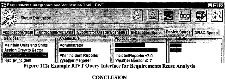
7. Requirements and Integration Verification Tool (RIVT): Assists stakeholders in system configuration
and interrogating requirements in the DRA and IRA from various perspectives (e.g. end-user questions, developer questions, system integrator questions). RIVT's querying capabilities encourage reuse by (i) aiding the identification and evaluation of applications against domain, application, and system infrastructure requirements and (ii) facilitating impact analysis as requirements and application technology change and/or evolve.
Using the DARPA emergency response project for illustration, the following subsections guide the reader through the activities depicted by the SEPA funnel, introducing the above tools as they become relevant.
V
•f* SEPA Activity: Knowledge Acquisition
All Users
HazMat
Specialist •/-Fire'' '-.' Police EMT
HazMat Incident Commander
Fire Incident Commander
f Fire Station ^ Administrator
Figure 11: Viewpoint Hierarchy The first step in gathering
requirements is to determine the stakeholder viewpoints or perspectives that must be considered when designing the system (Sommerville & Sawyer, 1997). Sommerville suggests that these viewpoints be gathered into a stakeholder viewpoint hierarchy. SEPA's Knowledge Acquisition Manager (KAM) tool actually uses two orthogonal hierarchies. The first hierarchy is used to describe the domain role viewpoints (with leaf nodes such as
HazMat Incident Commander or Fire Administrator). The second hierarchy is used to describe the organizational viewpoints (with leaf nodes such as City Y Fire Department or City X Police Department). While the KAM tool uses both viewpoint hierarchies simultaneously, this example will only use the shaded portion of the simple domain role viewpoint hierarchy shown in
Figure 11.
Domain experts for this project were selected so that a variety of expert viewpoints were represented, which for our example includes fire personnel and hazardous material specialists. The KAM tool was used to maintain contact information on project participants and allowed these domain experts to be assigned to leaf nodes of two hierarchies based on their domain role viewpoint and organization viewpoint. KAM was also used to schedule several KA Sessions with these experts and can record session information such as session goals, times, dates, locations, participants, and KA approaches.
Although KEs used a variety of approaches to elicit domain and system requirements, scenario analysis was the primary approach used to acquire domain task, performer, and timing information (Harbison, 1997). Other KA Sessions focused on acquiring specific implementation requirements through prototype review, yielding information about preferred look-and-feel as well as installation specifics such as required operating system. The SEPA example which follows is rooted in the information acquired from the sessions listed in Table 1.
Table 1; KA Sessions for Incident Response Example Session
1
2
3
Expert with Viewpoints Jim Hendrix - Hazardous Materials Specialist and HazMat Incident Commander • Sam Cook - Fireman, Fire Incident Commander, and Fire Station Administrator
Bob Smith - Fireman and Fire Incident Commander
Location :ity X -]ity Response
Center )ity Y -'ire Station 1
:ity Y -'ire Station 2
KA Approach Scenario Analysis Scenario Analysis Prototype Review Information Gathered Tasks, performers, and resources for chem/bio response
Tasks, performers, and resources for fire response
User Interface (UI) requirements and specific installation needs for fire response
To document each session, Knowledge Engineers (KEs) created one or more KA Session Reports, accompanied by supporting diagrams, videos, and supplemental documents. KA Session Reports represent knowledge from domain role and organizational viewpoints associated with the domain experts involved in each session. Knowledge Engineers use KAM to (1) identify domain experts, (2) define domain and organization viewpoints, (3) define an overall KA session plan, and (4) store the products from each session. Project participants can perform content-based searches with filters based on both domain role and organization viewpoints. These session reports, diagrams, videos, and supplemental documents provide the foundation for requirements traceability in the SEPA methodology.
SEPA Activity: Knowledge Modeling and Knowledge Model Synthesis Supporting Tools: Hybrid Domain Representation Archive (HyDRA) and
third party modeling tools
and creates structured graphical and textual Knowledge Models (KMs) in HyDRA and other third party modeling tools (e.g., Oracle Designer (Oracle, 1999)). Currently, the KE has the choice of a number of models, including data flow diagrams, task decomposition diagrams, task templates, Venn diagrams, entity-relationship diagrams, and concept maps. Appropriate knowledge models are selected based on the type of knowledge acquired. For example, task decomposition diagrams provide an overall view of domain tasks and subtasks, while a task template contains specifics about the data, timing, and performance requirements for a specific task. To facilitate the validation of KA artifacts with domain experts, each KA session yields a standalone collection of knowledge models called a Model Space (MS). The resulting knowledge models generated from the sessions in Table 1 are summarized in Table 2. Corresponding knowledge models are shown in Figure 7- Figure 12.
Table 2; Knowledge Models from Incident Response Example Knowledge Model
Venn Diagram (Figure 7Error! Reference source not found.) Task Decomposition (Figure SError! Reference source not found.)
Task Templates (Figure 9Error! Reference source not found.)
Task Decomposition (Figure lOError! Reference source not found.)
Task Templates (Not Shown)
Task Performance Constraint Template (Figure 1 1 Error! Reference source not found.) System Constraint Template (Figure 12Error! Reference source not found.)
Source
KA
Session
1
1
1
2
2
3
3
Data Represented
Attributes composing the "weather" concept.
Task decomposition for chem/bio incident response.
Selected task details for chem/bio incident response tasks, including pre/post conditions, performer, and input/output data.
Task decomposition for small fire incident response.
Selected task details for small fire incident response tasks, including pre/post conditions, performer, and input/output data.
Prototype presented to expert is associated with respective domain tasks as suggested implementation approach.
PsSVenn Editor
Fie Help
Diagram j mf0 | -rrace j History | Status j
o
HUID?*267-Wmd Direction
HUD #264-Temperalure
Select Tool
- ^—, J ~ , - .... . ,.., -A. ,-,..,AV.^
Select as View Point object
Figure 7: Venn Diagram from KA Session 1
Manage Responders During Incident
1.0
Assess Impact of Toxic Agent Release
2.0
Manage Sector Location
1.1
Create After Action Reports
3.0
Replay Incident 3.1
Create Incident Spill Report
3.2
Capture Weather Information
2.1
Determine Agent Dispersion and Possible Casualties
2.2
Gather Agent Characteristics
2.2.1
Determine Population Distribution
2.2.3
Gather Weather and Env. Parameters
2.2.2
Estimate Casualties
2.2.5
Create Dispersion Plume
2.2.4
Task: Manage Res ponders
During Incident
Precondltion: During Incident Postcondition: not specified Performer: Incident
Commander
Data Input: not specified Data Output: not specified
Task: Gather Weather and Env
Parameters
Precondition: not specified Postcondition: not specified Performer: not specified Data Input: Weather Data Output: not specified
Figure 9: Summary of Task Templates from KA Session 1
Manage Responds rs During Incident
1.0
Establish Env. for Local Installation
2.0
Assign Crew to Sector
1.1
Create After Action Reports
3.0
Maintain Units and Shifts
2.1
Manage Sector Location
1.2
Replay Incident 3.1
Create Incident Report
3.2
Figure 10: Summary of Task Decomposition from KA Session 2
To achieve a single, unified picture of requirements, HYDRA assists the KE in synthesizing requirements gathered from multiple experts, following a hierarchy of viewpoints defined for a domain. In this example, all models from "Hazardous Materials Specialist" experts would be merged into a "Hazardous Materials Specialist" model space (step 1 in Figure 13Error! Reference source not found.), and all models from "Incident Commander" experts would be merged into an "Incident Commander" model space (step 2 in Figure 13). These models space would subsequently be merged into a unified model space, the Unified Knowledge Model (UKM) (step 3 in figure 13).
Implementation ID: City Y Fire Dept. Constraints:
Operating System: Windows NT Memory: 128MB
Fixed Disk: 8 GB LAN: 10 Mbps Ethernet
Figure 11: Summary of System Constraint Template from KA Session 2
Task: Manage Responders During Incident Interface Prototype:
. Respondei Tiiinkc HHD
Prototype Description: Map-based approach
for assigning responders to various incident hotspots and tracking their location as an incident progresses.
KMsin KA Session 1 Model Space
KMsin KA Session 2 Model Space
KMsin KA Session 3 Model Space,
r
HazMat SpecialistKMsin Model SpaceKMsin Incident Commander
Model Space
KMsin Unified Knowledge
Model
Figure 13: Knowledge Synthesis Process
As synthesis proceeds, HyDRA detects conflicts between the knowledge models and presents the KE with possible resolutions. For example, when the ordering of two tasks vary between two models, HyDRA prompts the KE to choose which ordering to retain or to mark the tasks unordered. As each decision is made, HyDRA ensures the KE's rationale is captured. Traceability is retained to record how model elements were changed or merged to produce the resulting element. Details regarding the synthesis operation and representations can be found in (Barber & Jernigan, 1999).
Conflicts detected in this example along with their selected resolutions are:
1. Task with almost identical children: Task 3.0 in Figure 8 and task 3.0 in Figure lOError! Reference source not found, have the same name and share a common subtask. However, the other subtask (3.2) is different. During the merge, HyDRA detects this situation and asks the KE if it should (i) keep all three subtasks, (ii) ignore one of the dissimilar subtasks, or (iii) merge the two dissimilar subtasks into one task. In this case, the KE recognized that these are the same task and asked HyDRA to merge the two dissimilar tasks into one with the name "Create Incident Report." Alternatively, the difference between the subtasks under task 1.0, "Manage Responders During Incident," of the two task decompositions will not create a problem if the task decomposition from the first KA session (the session with only one subtask), is marked with an open world semantics or incomplete flag.
2. Type - usage conflict: HyDRA holds an ontology that specifies types of model elements, classifications of those model elements, and the relationships between those model types. The Venn diagram for "Weather" indicated the concepts in the diagram were "states" (not shown in panel exposed in Figure 7). However, the "Weather" concept was used in a task template knowledge model as a "resource" (Data Input in Figure 9). HyDRA detects this usage as being inconsistent with the type provided by the Venn diagram (Figure 7). Since, the knowledge models were validated by the domain experts before the merge, HyDRA cannot change them and preserve the validation. However, it can ask if the user would like to ignore the conflict, ignore the usage of "Weather" in the task template, or ignore the type information from the Venn diagram. Finally, the user has the choice of changing a source knowledge model, revalidating it with the domain expert, and re-performing the merge process. In the example, the KE chose to change the Venn Diagram so that it indicated that the concepts were to be classified as type "information," a non-volitional, intangible, and consumable kind of resource.
Establish Env. for Local Installation
1.0
Manage Responders During Incident
2.0
Maintain Units and Shifts
1.1
Assign Crew to Sector 2.1
Manage Sector Location
2.2
Create After Action Reports
3.0
Assess Impact of Toxic Agent Release
4.0
Replay Incident 3.2
Create Incident Report
3.1
Capture Weather Information
4.1
Determine Agent Dispersion and Possible Casualties
4.2
Determine Population Distribution
4.2.3
Gather Weather and Env. Parameters
4.2.2
Estimate Casualties
4.2.5
Create Dispersion Plume
4.2.4
Figure 14: Merged Task Decomposition from UKM
Following the synthesis operations depicted in Figure 13, the incident response UKM should include concepts originating from the combined set of knowledge models. The merged task decomposition information in the UKM is illustrated in Figure 14 for clarity.
SEPA Activity: Separation of Domain and Application Requirements Supporting Tool: SEPArator
The UKM artifact provides a single, consistent model that becomes the basis for all further requirements analysis in the SEPA methodology. Before a Domain Reference Architecture can be derived, domain requirements must be separated from application requirements in the UKM. SEPArator aids the process of identifying domain content in the UKM, originally represented as concept models (such as the Venn Diagram in Figure 7) and task-based models. The resulting extraction of domain requirements is captured as the Domain Model (DM). In contrast to concept and task-based models, task performance constraint and system constraint models (Figure 11 and Figure 12) are used to characterize currently available or desired applications and sites. This information is subsequently instantiated in the Infrastructure Reference Architecture (IRA), and becomes particularly relevant during technology registration and system design. In this example only domain requirements were elicited from KA sessions 1 and 2. Application requirements were elicited from KA session
3.
fT ^ ^^SEPA Activity: Reference Architecture Derivation and Application Registration \ \~^~\ Supporting Tools: Reference Architecture Representation Environment (RARE)
\J and Application Specification Environment and Registration Tool (ASERT)
The domain requirements represented in the Domain Model (DM) reflect the synthesis of domain tasks and data expressed by stakeholders and compiled by KEs. This knowledge is captured with respect to scenarios of operation. Stakeholders describe their jobs, the data they exchange, and the technology they use in the context of those scenarios. Given this elicitation approach, the DM follows a functional, rather than object-oriented, decomposition. However, to encourage the reuse of requirements and applications in multiple system configurations, SEPA mandates that domain requirements be organized into object-oriented classes to which applications are registered.
Architecture Classes (DRACs) and the allocation of tasks and data represented in the DM to specific DRACs. The DRA serves as a blueprint for developers, where each DRAG specifies domain data owned, domain services (tasks) provided, and data and event dependencies with other DRACs. These dependencies arise from data and events exchanged between services in different DRACs.
Domain tasks, data, and events can be allocated among classes in a number of possible combinations. As with traditional object-oriented analysis, the identification of classes is not an exact science but strongly depends on the priorities and skills of the analyst. Furthermore, an entire object-oriented model is rarely defined in a single iteration; the model is typically refined over multiple passes. RARE supports the iterative nature of object-oriented analysis and applies proven object-object-oriented heuristics based on priorities established by the analyst. To document the analyst's decisions and the evolution of the DRA, the analyst's rationale is captured and traceability to DM tasks and data is established.
To drive the allocation process, RARE follows a set of high-level goals prioritized by the architect. Four primary goals were emphasized in the DARPA emergency response project:
1. Align DRACs with task performers in the domain: Many domain tasks will remain un-automated, thus the collections of tasks assigned to a DRAG should closely follow the tasks assigned to the respective domain performer (e.g. Incident Commander).
2. Align DRACs with existing COTS applications: To maximize reuse of existing COTS applications capable of performing domain tasks, tasks should be grouped based on those tasks associated with existing applications.
3. Create classes that increase installation customizability: To increase customizability for each installation, it is recommended to reduce the number of services offered by each DRAG and thus increase the total number of DRACs. In general, a greater number of smaller DRACs can be combined in more arrangements to support specific installation requirements.
4. Allocate tasks among classes based on when tasks are typically performed during an incident response: Incident responders only concern themselves with a certain set of tasks during any particular time period of an incident. For example, tasks such as assigning crews to shifts and defining resources (e.g. fire trucks) are done outside of any particular incident. Tasks in different time periods naturally have fewer coupling constraints than tasks in the same time period. Therefore these large grained time periods provide guidance for the assignment of tasks to DRACs so that inter-DRAC coupling and the number of DRACs the responder must interact with during any given period are reduced.
A subset of the DRA produced for the DARPA emergency response project is depicted in Figure 15 below. The "Incident Manager" DRAG was created based on goal 1, while the creation of the "Weather Manager" DRAG was strongly influenced by goal 3.
DRAG: Incident Manager Services:
• Assign Crew to Sector » Manage Sector Location
DRAG: Weather Manager Services:
• Capture Weather Information
Contributing Goal: Align DRACs with task performers in the domain.
Rationale: The domain role of Incident Commander is significant.
Contributing Goal: Create classes that increase installation customizability
Rationale: Weather data should be
independently managed from other types of data so data handlers can be combined in different ways for different installations.
FigurelS: Subset of Domain Reference Architecture
Once the DRA is defined, the process of associating a new, existing, or proposed (notional) end-user application with DRAG data and functionality is referred to as "registration." The ASERT tool allows the developer to identify DRAG data and services provided by both COTS applications and customized applications. In this example, the applications under consideration and the domain services they provide include the following: • FDManager v2.0 - A COTS application that provides a complete set of services to support small and
midrange incidents. These services include resource allocation and responder assignment and tracking. FDManager v2.0 provides DRAG services:
ResponderLocator vl.O - A newly developed map-based application used to assign tasks and locations to responders and monitor their location. ResponderLocator vl.O provides DRAG services:
"Assign Crew to Sector" in DRAG Incident Manager "Manage Sector Location" in DRAG Incident Manager
WeatherMonitor vO.7- A newly developed application that provides an interface for collecting weather data and disseminating this data to multiple responders. WeatherMonitor vO.7 provides DRAG service "Capture Weather Information" in DRAG Incident Manager.
^-—-j?^---SEPA Activity: Application Requirements Modeling
| ff Supporting Tool: Modeling Environment for Technology Requirements (METeR)
Associating an application to respective DRAG services is only part of the registration picture. During system design, the system integrator performs a brokering activity based on "how" an application performs its functions as well as "what" domain tasks the application provides. Thus, an application must also be characterized by "application requirements," including specific implementation features and infrastructure needs.
The ASERT tool allows an application to be registered against both DRACs and IRACs. Figure 16 depicts both the "what" and "how" registration mappings for the FDManager v2.0 and ResponderLocator vl.O applications listed above. Registering against a DRAG specifies "what" an application does; while registering against an IRAC specifies "how" the application does it. As described in Section 0, SEPA's IRAC ontology is used to represent domain-independent knowledge about application requirements. Following the separation process aided by the SEPArator, the METeR tool assists system stakeholders in representing application requirements, originally from the UKM, using the IRAC ontology (e.g. task performance constraint and system constraint requirements from KA session 3). The IRAC ontology is used to represent both the application requirements expressed by stakeholders and the specifications of an application being registered through ASERT.
DRAG: Incident Manager
A
End-User Application:
FDManager 2.0
Assign Crew to Sector Manage Sector Location
End-User Application:
Respond er Locator 1.0
Assign Crew to Sector
IRAC: Software Application
Name: FD Manager 2.0 executable
0>
al
$
IRAC: Operating System
Type: Microsoft Windows 32-Bit OS
IRAC: Computing Platform
Processor Type. Intel Pentium
Class
Processor Speed > 90 MHz Main Memory. > 32 MB Disk Storage: 2 5 MB
Display Device: 640x480x256
IRAC: Software Application
Name: Responder Locator 1.0 executable <D
"83
s
IRAC: Runtime Library
Name: XML Library 1.1.1
IRAC: Middleware Data Handler
Name: Incident Middleware 0.8
IRAC: Runtime Environment
Type: Java2 Runtime Environment
Figure 16: Application Registration Example
With an understanding of the domain and application requirements for a particular installation, the system integrator performs the activity of system design by selecting specific applications that together comply with the client's installation requirements.
registered applications, SEPA's separate domain and application requirements representations are used to aid the designer in identifying potential system designs and candidates for reuse.
Beginning with a blank slate, system design typically starts with a questions such as "What domain tasks should be automated at this installation?" SEPA tools help the designer to answer this question independently of implementation concerns by perusing the domain model and/or reference architecture to identify candidate tasks. Browsing the reference architecture is often preferred since services are likely organized into DRACs that correspond to familiar domain roles (e.g. Incident Commander role, HazMat Specialist role).
For City X, two required domain functions documented in KA session 1 are: • Manage Sector Location
• Capture Weather Information
Once the respective set of DRACs has been identified, the Requirements Integration and Verification Tool (RIVT) can be used to determine registered applications capable of performing the selected domain tasks. Based on the domain services selected for City X, candidate applications suggested are:
• Manage Sector Location - FDManager \>2.0 OR ResponderLocator vl.O • Capture Weather Information - WeatherMonitor 0.7
For City X, neither task constraints nor system constraints have been specified. Thus the designer may select either FDManager v2.0 or ResponderLocator vl.O to provide the "Manage Sector Location" service. The designer narrows the set of candidate applications by imposing implementation requirements. These requirements (constraints) are expressed in the same language as the application registered infrastructure, the IRAC ontology. Once the designer has successfully satisfied the domain and application requirements associated with each application, the brokering process continues by evaluating (i) the compatibility of the application collection against the system environment and (ii) the mutual compatibility of the applications. Specific IRAC information relevant to this example includes the following:
• FDManager v2.0
• Processor Type: Intel • Processor Speed: > 90 MHz • Disk-space: > 5 MB • Memory: > 32 MB
• Display Size: 640x480x256
• requires-OS: { Windows NT Workstation v4.0 SP4 I Windows 95 I Windows 98 } • ResponderLocator vl.O
• requires-OS: { Windows NT Workstation v4.0 SP4 I Windows 95 I Windows 98 } • depends-on-application-framework: IncidentMiddleware vO.8
• uses-system-library: XMLLibrary v 1.1.1
• executes-in-runtime-environment: JavaRuntimeEnvironment vl.2 • depends-on-application-framework: IncidentMiddleware vO.8 • WeatherMonitor 0.7
• requires-OS: { Windows NT Workstation v4.0 SP4 I Windows 95 I Windows 98 } • executes-in-runtime-environment: JavaRuntimeEnvironment vl.2
In addition to highlighting possible incompatibilities among applications, the integration process also highlights the need for secondary supporting applications, such as databases, word processors, and web servers. These related infrastructure applications may, in turn, have further infrastructure needs. For example, the infrastructure application IncidentMiddleware vO.8 required by Responder Locator vl.O, requires the storage repository IncidentRepository v2.0.
• In contrast to the City X installation, options for the City Y installation are constrained by the requested map-based user interface and the required operating system (Windows NT) based on KA session 3.
Applications used in the City X installation are reused for the City Y installation based on their registration to required tasks, providing they satisfy the stated application requirements. These requirements help narrow the set of feasible application, resulting in selection of Responder Locator vl.O to provide the "Assign Crew to Sector" task, since the task is constrained by the requirement for map-based application.
^-—-SEPA Activity: Requirements Analysis
Supporting Tool: Requirements and Integration Verification Tool (RIVT)
Impact analysis for new application development
In a domain as complex as Incident Management, the domain scope modeled will likely need to grow to satisfy a larger customer base. Through KA, new domain tasks are added in context with existing functionality. Relationships to existing tasks are determined during knowledge model merging and filtered down to the RA as changes in data and event exchange between DRAG services.
When new applications are under consideration, an initial analysis of the Reference Architecture and currently registered applications can provide information regarding the degree to which a proposed application will affect or be affected by other applications. Functionality to be provided by the new application is identified in the RA. If the domain task has not yet been represented in the RA, additional KA yields an expanded DM and results in new RA services. Likely interaction among applications is evident through data and event exchange between the DRACs that provide the functionality under consideration. These interactions can identify (i) other applications already registered which may require modification to correctly interface with the new application and (ii) functionality which has not yet been automated but must now be automated if the functionality under consideration is to be included in the system design.
Requirements analysis to support reuse of existing applications
The SEPA process and tools enable reuse of requirements through requirements modeled in a computational representation. Application implementation and domain requirements represented in SEPA can be used in combination to determine the likelihood of reuse.
As in the brokering examples described in the prior section, the first step in satisfying the needs of an installation site is determining which domain tasks are to be supported. Through application registration against the RA, these domain tasks reference applications that become candidates for reuse. To identify domain functionality of interest, the RIVT user can take a number of approaches in posing questions to the RA.
Users focused on particular domain data elements: Data elements represented in the Domain Model are
"owned" by DRACs in the RA. RIVT can be used to determine what DRAG services utilize those data elements and what applications are registered to those services.
Users familiar with high-level domain tasks that are to be automated: High-level tasks in the DM identify lower level tasks that are satisfied by DRAG services in the RA. RIVT can be used to determine what applications are registered to those tasks/services.
Users intending to automate the tasks for a particular domain role (performer): Tasks performed by a domain role (e.g. Incident Commander) are identified in the DM; those tasks are satisfied by services in one or more DRACs. Furthermore, DRACs often closely align with performer roles, thus collecting the services associated with a role. RIVT can be used to determine what applications are registered to the service associated with DRACs.
Once a selection of candidate applications is identified for reuse, infrastructure requirements associated with registered applications provide additional information for determining level of reuse. Questions that can be answered using the SEPA IRAC representation include:
• What types of resources does the application require (e.g. hard disk, memory, peripherals)?
• Does the application run in the chosen runtime environment (e.g. Java, Visual Basic for Applications)? • Does the application run under the chosen operating system?
• Will an application conflict with other candidate applications if integrated in a single installation (e.g. the sum of memory required by two applications exceeds that offered by the destination server)?
• Considering the pool of available application developers, is the application developed using skills developers possess and technologies they are familiar with (e.g. Java, Visual Basic)?