Published online May 30, 2013 (http://www.sciencepublishinggroup.com/j/wcmc) doi: 10.11648/j.wcmc.20130101.14
Performance evaluation of cooperative multi-layer IDMA
communications with amplify-and-forward protocol
Basma A. Mahmoud, Esam A. A. Hagras, Mohamed A. Abo El-Dhab
Department of Electronics & Communications, Arab Academy for Science, Technology & Maritime Transport, Cairo, Egypt
Email address:
[email protected](B. A. Mahmoud), [email protected](E. A. A. Hagras), [email protected](M. A. A. El-Dhab)
To cite this article:
Basma A. Mahmoud, Esam A. A. Hagras, Mohamed A. Abo El-Dhab. Performance Evaluation of Cooperative Multi-Layer IDMA Communications with Amplify-and-Forward Protocol. International Journal of Wireless Communication and Mobile Computing. Vol. 1, No. 1, 2013; pp. 21-25. doi: 10.11648/j.wcmc.20130101.14
Abstract:
In this paper, we consider the Bit Error Rate (BER) performance analysis of a cooperative relay communication system for Multi-Layer IDMA (ML-IDMA) using Maximal-Ratio-Combining (MRC) technique. We examine the effect of layers number on the performance and derive the average bit error probability of the Amplify-and-Forward (AF) relay scheme by using the closed-form relay link Signal-to-Noise Ratio (SNR). The proposed system has been simulated to evaluate the performance of ML-IDMA with different numbers of layers and different number of relays in the ML-IDMA cooperative environment. The simulation results show that the BER performance has been improved by about 4dB in the case of double layer (K=2) IDMA system with 4-relays, also, the saving in the band width is 50%. Finally, the BER performance has been degraded with increasing in the number of layers and the proposed system has improved the band width by about 1/K.Keywords:
Cooperative Transmission, Multi Layers, MRC, AF1. Introduction
Multiple-Inputs Multiple-Output (MIMO) technology is widely used due to its ability to offer high diversity and multiplexing gain. The Impracticality of mounting multiple antennas on a mobile device favor other techniques to be used in wireless communication and these techniques are also designed to have less impact on the size and power consumption of the devices. Recently, it has been shown that, in a cooperative system, two or more users cooperate with each other to transmit information to the destination. The cooperative users can share each other’s antennas to form a virtual multiple antenna system so that a single antenna device can also benefit from the spatial diversity provided by the cooperative users. In such a way, cooperative communication allows a source node with a single antenna to share the antennas of other nodes, resulting in a form of virtual MIMO system.
User cooperation systems that utilize different cooperative signaling methods are known to improve cellular system capacity and coverage. The relay node physical limitation and allowed signaling complexity are the two criteria that limit the used cooperation system. In [1, 2] several cooperative diversity protocols were developed
and analyzed; Amplify-and-Forward (AF), Decode-and-Forward (DF), Detect-and-Decode-and-Forward (DtF), Estimate-and-Forward (EF) and Selective-DF (S-DF).
In AF protocol, relay nodes amplify the signals received from a source node and transmit the amplified version of the signals to a destination node. In EF, the relays forward an estimate of its received signals to the destination .For DtF, the relays detect the received signals and forward the detected symbols to the destination. For DF, the relay nodes decode the information received from the source and re-encode the signal before transmitting it to the destination. For S-DF, only those nodes that can correctly decode are selected to forward the signals to the destination [3].
multiple access communication, is an important unique advantage of the IDMA that can add to its bandwidth efficiency as well as high transmission speed of data [5].
The principle of the IDMA systems is that the chip-level interleavers should be different for different users. In addition, a low-cost chip-by-chip iterative detection scheme can be utilized in the IDMA systems. Motivated by the concept of IDMA, Superposition Coded Modulation (SCM) partitions the data to multi layer, where each layer is treated by a user equivalently [6]. Multi-layer IDMA (ML-IDMA) is a special form of superposition coding scheme and it can be considered as a joint modulation/channel coding transmission scheme. Based on these backgrounds, according to the above observations, we propose a cooperative transmission scheme based on ML-IDMA.
In [5, 7-9], authors’ have paid attention to the one layer IDMA cooperative system and without using any combiner technique at the destination. In this paper, we carry out the performance analysis of cooperative single user ML-IDMA scheme for equidistant relaying geometry with different number of layers and a Maximal-Ratio-Combining (MRC) technique; relay protocol that is used in this paper is Amplify-and-Forward (AF). The rest of the paper is organized as follows: in Section 2, we discuss the ML-IDMA system with AF Protocol; the experimental result is presented in Section 3; while conclusions and future works are presented in Section 4.
2. ML-IDMA System with AF Protocol
Amplify-and-forward is a simple cooperation scheme, in which relay does not require extra processing capability but still can achieve full diversity [10]. The only drawback in this scheme is that it amplifies the received signal along with inter-user channel noise. That means that it cannot eliminate the noise from the received signal, also termed as non-regenerative relaying protocol.
In an IDMA technique with an AF protocol, the source transmits a signal to a relay followed by amplification of the received signal that is controlled by an amplification factor as well as the power constraints. The amplification factor was shown to have an inverse relation to the received power [11].
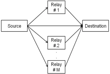
We consider the cooperative system in Figs. 1-4. The system consists of a source (S), M relays, and a destination (D). The signal is transmitted from the source through two phases, first the source broadcasts the signal to the relays then the relays transmit the signals to the destination.
In our design, the source/user generates an input data sequence d = [d (1), d (2) . . . , d (N)] which is converted by serial-to-parallel converter into K subsequences layers. Then the data, in each layer, is spreaded, interleaved and modulated, independently. Finally, all data in K layers are linearly superimposed to transmission then the source broadcasts the superimposed signal to the relays.
Figure 1. System model of cooperative ML-IDMA with multiple relays.
Figure 2. ML-IDMA transmitter (Source)
Figure 3. Relays with amplify-and-forward protocol
Figure 4. ML-IDMA Receiver (Destination)
For K-layer, the data sequence dk = [dk (1), dk (2)..., dk (I)] is first spreaded, generating a spreaded sequence sk = [sk (1), sk (2)…., sk (J)] then the spreaded sequence sk is
interleaved by a distinct chip-level interleaver πk to produce
a permutated sequence sk. After interleaving, the randomly
sequence skis modulated to xk = [xk (1), xk (2) . . . , xk (J)]
by BPSK. Where I=N / K, N is the user data length and I is the layer data length.
The transmitted signal xs, after sum mission from K
Layers, is then given by:
By assuming that each terminal has one antenna; each relay amplify the received signal and retransmit it to the destination and that the channels between the source and each relay is a quasi-static Rayleigh fading channel with Additive White Gaussian Noise (AWGN), the received signal ys,r, at the relay, is given by:
, , , (2)
and the received power is given by: , , , (3a) , , (3b) , (3c) where 0=2!2 is the average noise power. The amplification coefficient is given by: " # $% $% &',( )*+, (4)
By normalizing the power to P.=1, ys,r is given by: , , , (5)
" # &',()*+, (6)
The fading amplitude and noise were considered by amplification coefficient. Some other amplification coefficients were proposed in [12]. Amplification coefficients similar to this paper were also suggested by [10, 11, 13, 14]. This kind of amplification factor considers the channel response of inter-user channel and effect of noise when added to the received signal. The signal after amplification is given by: x0 β y3,0 (7a) x0 β x3h3,0 n3,0 (7b) The relayed signal when received at destination is given by: y0,6 h0,6x0 n0,6 (8a) h0,67β x3h3,0 n3,0 8 n0,6 (8b) The received signal at the destination at the first phase is given by: y3,6 h9,6x3 n3,6 (9)
The total received signal for Maximum-Ratio-Combining (MRC) receiver is given by: r h3,6; y3,6 ∑>? h3,0; =;h;0=,6 y0=,6 (10)
Using a single-path / one relay system, Eq. (10) is: r h3,0; ; h0,6; y0,6 (11a) r h3,0; ; h0;,6 h0,6x0 h3,0; ; h0;,6 n0,6 (11b) Where h = h3,0; ;h0;,6 h0,6 and n = h3,0; ;h0;,6 n0,6 r h B@ x@ j n j (11c) Where “n” represents the composite noise, h3,6 is the channel coefficient between the source and the destination, h3,0 is the channel coefficient between the source and the relay,h0,6 is the channel coefficient between the relay and the destination and “n” is a sample of an AWGN process with zero mean and variance σ2 per dimension. We adopted an iterative sub-optimal receiver structure, as illustrated in Fig. 4 which is composed by an elementary signal estimator (ESE) and K de-spreaders (DESs). They are applied to solve inter-layer interference and the spreading constraint separately. The receiver performs the iterative processes to update the extrinsic information between ESE and DESs [15, 16]. For the detection of layer-k, we can rewrite Eq. (11c) as: r j hx@ j ξ@ j , j 1, 2…, J 13
where, ξ@ j , represents the interlayer interference with respect to layer-k. The ESE function is used to calculate the extrinsic log-likelihood Ratios (LLR) for estimating the transmitted signal. From the definition of the extrinsic LLR, the output of ESE function can be obtained by: eH9H x@ j 2h.0 J KHMN0ξξLJ LJ 14
where, E r j h ∑ E x@ @ j 15
Var r j |h| ∑ Var x@ @ j σ 16
E 7ξ@ j 8 E r j V h E x@ j 17
Var 7ξ@ j 8 Var r j V |h| Var x@ j 18
The mean and variance of can be calculated by the feedback from DESs, as follow: E x@ j tanh Z[\]^_LJ ` 19
Var x@ j 1 V E x@ j 20
3. Simulation Results
In this paper, we carry out the performance analysis of cooperative single user ML-IDMA scheme for equidistant relaying geometry with different number of layers and a MRC technique. The applied relay protocol is Amplify-and-Forward (AF), which is implemented for the system that uses Binary Phase Shift Keying (BPSK). MATLAB is used to simulate the obtained results. In this paper it is assumed that all stations are arranged at the edges of a square with a length of one. That means that all channels will have the same path loss and therefore the same average Signal-to-Noise Ratio (SNR).
To simulate the cooperative ML-IDMA scheme, we assume that the channel is Rayleigh fading channel, equidistant relaying geometry, BPSK signaling is used, frame length (N) = 512, Spreading Length (SP) =32, number of relays (R) =1…, 4, number of layers (K) =2, 4 and number of iteration (it) =3.
Fig 5. BER of cooperative ML-IDMA in Rayleigh channels with K=2, 4, N=512, it=3, SP=32 and R = 1
Fig. 5 shows that there is degradation in the BER performance by increasing the number of layers. In the case of without relay, K=2 and Eb/N0=15 dB, the BER performance was 1.9*10-4 while increasing K to 4, degraded BER performance to 6.6*10-3.The observed degradation in the BER performance by increasing the number of layers is due to increasing in the signal amplitude which cause signal distortion. For single relay (R=1), in the case of double layer (K=2), the improvement of the BER performance is 1.67 dB compared to without relay system. Also in the case of four layer (K=4) and Eb/N0 = 20 dB, the BER improvement was found to be about 2.6 *10-3 when compared to without relay system as shown in Fig.5.
Fig.6 shows the improvement in BER performance by increasing the number of relays to R=4 at K=2 by about 4 dB when compared to without relay system. Fig. 7 show that R= 4 is superior to the case of R=1 by about 3.5 dB at the BER of 10-4. We can conclude that the co-operative environment, which added up two signals of different links, performs better than systems designed without relay environment. We can also see that when additional relay is
deployed, the performance in the co-operative environment gets better. The analysis showed that the addition of different path powers in co-operative environment results in a lower Bit-Error-Rate (BER).
Fig 6. BER of cooperative ML-IDMA in Rayleigh channels with K=2, 4, N=512, it=3, SP=32 and R = 4
Fig 7. BER of cooperative ML-IDMA system in Rayleigh channels with R= 1, 2, 3, 4, K=2, N=512, it=3 and SP=32
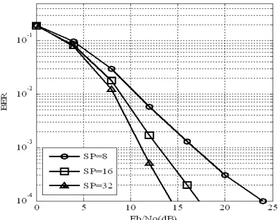
Fig 8. BER of cooperative ML-IDMA system in Rayleigh channels with SP=8, 16, 32, R=1, K=2, N=512 and it=3
4. Conclusion
In this paper, a cooperative communication scheme based on ML-IDMA technique is proposed for a network which has one source, one destination and multiple common relays. The proposed system is based on the chip-by-chip detection algorithm. Data reaches the destination through two different paths, i.e. a direct path from source to destination and a relayed path, where Amplify-and-Forward AF relay protocol is applied to the data that finally reaches the MRC combiner at the destination.
The proposed system has been simulated to evaluate the performance of ML-IDMA technique with different numbers of layers with Maximal-Ratio-Combining (MRC) technique in the cooperative environment. The simulation results showed that by increasing the number of layers, degradation in the performance was obtained but on the other hand the Band Width (BW) was saved by (1/K).
The simulation also showed that the cooperative environment, which added up two signals of different links, performed better than the system designed without relays. When an additional relay was deployed, the performance in the cooperative environment got better. This improvement means that the addition of different path powers in cooperative environment actually results in a lower Bit Error Rate (BER) in the Eb/N0 vs. BER curve. We also observed that, the performance of cooperative environment with two or more relays is better in all investigated layers. Future work will be done to investigate the performance of coded ML-IDMA cooperative schemes, OFDM ML-IDMA, Coded OFDM ML-IDMA.
References
[1] J. N. Laneman, and G. W. Wornell, “Distributed Space-Time-Coded Protocols for Exploiting Cooperative Diversity in Wireless Networks," IEEE Trans. Inf. Theory, vo.49, no.10, pp.2415-2425, Oct 2004.
[2] G. Scutari, S. Barbarossa," Distributed space-time coding for regenerative relay networks," IEEE Trans. Wireless Commun., vol.4, no.5, pp.2387-2399, Sept. 2005.
[3] Jinhong Yuan, Yonghui Li, and Li Chu, “Differential Modulation and Relay Selection WithDetect-and-Forward Cooperative Relaying,” IEEE Trans. ON Vehicular Technology, vol. 59, no. 1, jan. 2010
[4] L. Ping, L. Liu, K. Wu, and W. K. Leung, “Interleave-division multiple access,” IEEE Trans. Wireless Commun., vol. 5, no. 4, pp. 938-947, Apr. 2006.
[5] Zhifeng Luo, Deniz Gurkan, Zhu Han, Albert Kai-sun Wong and Shuisheng Qiu,” Cooperative Communication Based on IDMA,” 5th International Conference on Wireless Communications, Networking and Mobile Computing, pp.1-4, Sep. 2009.
[6] J. Tong, P. Li, Z. H. Zhang, and W. K. Bhargava, “Iterative Soft Compensation for OFDM Systems with Clipping and Superposition Coded Modulation,” IEEE Trans. Commun., vol. 58, no. 10, pp. 2861–2870, Oct. 2010.
[7] Xiaotian Zhou, Haixia Zhang and Dongfeng Yuan,”A multi-source cooperative scheme based on IDMA aided superposition modulation,” International Conference on Information Theory and Information Security, pp.802-806, December 2010.
[8] Weitkemper, P. , Wubben, D. and Kammeyer, K.-D.,” Delay-diversity in multi-user relay systems with Interleave Division Multiple Access,” IEEE International Symposium on Wireless Communication Systems 2008, pp.364-368, October 2008.
[9] Chulhee Jang and Jae Hong Lee, “Novel IDM-cooperative diversity scheme and power allocation,” in Proc. IEEE APWCS 2009, Seoul, Korea, pp.24-28, Aug. 2009.
[10] J. N. Laneman, D. N. C. Tse and G. W. Wornell, “Cooperative Diversity In Wireless Networks: Efficient Protocols And Outage Behavior,” IEEE Trans. Info. Theory, Vol. 50, No. 12, pp. 3062-3080, November 2004.
[11] K. J. R. Liu, A. K. Sadek, W. Su and A. Kwasinksi, Cooperative Communication and Networking, New York: Cambridge University Press, 2009.
[12] D. Chen and J. N. Laneman, “Cooperative Diversity For Wireless Fading Channel Without Channel State Information,” IEEE Trans. Wireless Comm. vol. 5, No. 7, pp. 1307-1312, July 2006.
[13] M. Yuksel and E. Erkip, “Diversity in Relaying Protocols with Amplify and Forward,” IEEE GLOBECOM Communication Theory Symposium proceeding, San Francisco, pp. 2025-2029, December 2003.
[14] P. A. Anghel and M. Kaveh, “Exact Symbol Error Probability of a Cooperative Network in a Ryaleigh-Fading Environment,” IEEE transaction on wireless communications, vol. 3, No. 5, pp. 1416-1421, September 2004.
[15] Takyu O, Ohtsuki T, Nakagawa M. Companding system based on time clustering for reducing peak power of OFDM symbol in wireless communication. IEICE Transactions on Fundamentals of Electronics Communications and Computer Sciences 2006; E89- A(7):1884–91.
[16] J. Akhtman, B. Z. Bobrovsky, and L. Hanzo, “Peak-to-average power ratio reduction for ODFM modems,” in Proceedings of the 57th IEEE Semi-Annual Vehicular Technology Conference (VTC’03), vol. 2, Apr. 2003, pp. 1188–1192.