STRUCTURAL ANALYSIS OF BRAKE DISC
PLATE USING THREE DIFFERENT
MATERIALS
Pappuri Hazarathaiah*, Assistant Professor, K.Venkateswarlu, Assistant Professor,
and M.Sreenivasulu, Professor,
Department of Mechanical Engineering, N.B.K.R. Institute of Science and Technology, Vidyanagar
Andhra Pradesh, India - 524 413.
Abstract—Disc(Rotor) brakes are exposed to large thermal stresses during routine braking and extraordinary thermal stresses during hard braking. The aim of the project is to design, model a disc. Modeling is done using NX/UG. Structural analysis is to be done on the disc brakes using three materials Stainless Steel and Cast iron carbon carbon composite. Structural analysis is done on the disc brake to validate the strength of the disc brake. Comparison can be done for deformation, stresses etc. form the three materials to check which material is best. NX/UG is a 3d modeling software widely used in the design process. HYPERMESH is general-purpose finite element analysis (FEA) software package. Finite Element Analysis is a numerical method of deconstructing a complex system into very small pieces (of user-designated size) called elements.
Keywords—Brake Disc Plate and Finite Element Analysis (FEA)
I. INTRODUCTION
The ever increasing need of effective transportations puts automobile manufacturers in a non-avoidable situation of de-livering safer, cheaper and more effective cars. For a car manufacturer, it is necessary to keep up with competitors within these areas in order to maintain and attract consumers. According to ASIRT (2013), nearly 1.3 million people world-wide die in traffic accidents every year, which makes a rate of 3,287 deaths each day, and approximately 30 million people are disabled or injured, mostly younger people between 15 and 44 years of age. Due to statistics like this, the need for safer cars today becomes more and more important and the requirements of safety systems of the cars even tougher.
Volvo Car Corporation (VCC) is one of the strongest auto-mobile industry brands with a very long and proud history of state of the art, world leading innovations. Today, VCC is one of the very leading car manufacturers in the world considering traffic safety engineering and has long been stressed and marketed for their historical reputation of solidity, reliability and safety. To maintain and improve safety systems in order to adapt to the ever toughening safety requirements without increasing vehicle weight, more and more active safety systems are today developed. However, the brake system has always been one of the most critical parts when requirements like these have to be met.
In most of the modern cars today, disc brakes are used on the front wheels and in most cases also on the rear wheels. The main purpose of a disc brake system is to decelerate the vehicle by transforming the kinetic energy of the car into thermal energy by friction between the brake disc and the brake pads.
The driver decides when to decelerate the vehicle by pushing the brake pedal which determines the brake fluid pressure inside the hydraulic circuit. To increase the hydraulic pressure higher than the force applied from the driver, a booster is used which uses vacuum. For gasoline engines, this vacuum usually comes from the vacuum that occurs in the intake manifold of the combustion engine. For diesel engines, a separate vacuum pump is instead often used. This amplified force that comes out of the booster goes into the master cylinder which distributes the pressure out to each caliper.
A disc brake system which uses fixed coupled pistons, e.g. one, two or three pistons on each side, is called a fixed caliper braking system. Pistons on both sides are pushing respective brake pad directly against respective side of the brake disc, to create a frictional force which provides a braking momentum on the rotor.
The main function of a brake disc system was explained, to reduce the kinetic energy of the vehicle by partially translating the energy into heat. The energy transformation is mainly made through the friction contact between the brake pads and the brake discs. When the brake pads are applied onto the brake disc, the pads will generate a brake force onto the brake disc which further generates a resisting torque on the wheel.
The resisting opposite torque of the wheel torque comes from the ground by friction between the tyre and ground contact patch which further will decrease the vehicle speed. First, elastic energy is built up in the tyre due to elastic deformation to build up the friction force of the contact patch.
Not all absorbed heat energy is directly due to deceleration of the vehicle in the very start of braking, first elastic deforma-tion of the chassis and suspension take place which absorbs energy. Also if the brake force is to large, slip will appear and there also generate heat energy instead of decreasing the kinetic energy.
The two brake disc designs [2] that are used in this experi-ment are two 18 front bra e discs that look exactly the same besides the vane designs; pin design and straight ventilations channel design. In that way a fair comparison can be made out of a cooling vane design point of view.
II. LITERATURE REVIEW
Thermal simulation of complex mechanism performance [3] is based on the simultaneous use of analytical methods for simple shaped moving parts and numerical techniques (Finite Element Method) of the others. The method presented called Hybrid method, uses these two techniques for 2-D and 3-D cases. A particular formulation of analytical results insures the compatibility with the Finite Element Method. Large CPU time savings are obtained when compared to a pure numerical analysis.
Won Sun Chung[2] presents an analysis method to estimate the thermal performance of a disc in a vehicle considering braking conditions and the characteristics of hydraulic devices such as the booster, master cylinder and proportional valve. The whole braking pressure transfer process in the hydraulic brake system from its generating by the pedal to action on the pad is analytically determined.
Faramarz Talati and Salman Jalalifar [4] the governing heat equations for the disk and the pad are extracted in the form of transient heat equations with heat generation that is dependant to time and space. In the derivation of the heat equations, parameters such as the duration of braking, vehicle velocity, geometries and the dimensions of the brake components, materials of the disk brake rotor and the pad and contact pressure distribution have been taken into account.
A. Yevtushenko and R.Chapovska [5] a transient contact problem with frictional heating and wear for two nonuniform sliding half-spaces is considered. One of the two half-spaces is assumed to be slightly curved to give a Hertzian initial pressure distribution: the other is a rigid nonconductor. Under the assumption that the contact pressure distribution could be described by Hertz formulas during all the process of interaction, the problem is formulated in terms of one integral equation of Volterra type with unknown radius of contact area. A numerical solution of this equation is obtained using a piecewise-constant presentation of an unknown function. The influence of operating parameters on the contact temperature and the radius of the contact area is studied.
First-generation CAD software systems were typically 2D drafting applications developed by a manufacturer’s internal IT group (often collaborating with university researchers) and primarily intended to automate repetitive drafting chores. Dr. Hanratty co-designed one such CAD system, named DAC (Design Automated by Computer) at General Motors Research Laboratories in the mid 1960s.
In 1965, Charles Lang’s team including Donald Welbourn and A.R.Forrest, at Cambridge University’s Computing Labo-ratory began serious research into 3D modeling CAD software. The commercial benefits of Cambridge University’s 3D CAD software research did not begin to appear until the 1970 however, elsewhere in mid 1960s Europe, French researchers
were doing pioneering work into complex 3D curve and surface geometry computation. Citroen’s de Casteljau [6] made fundamental strides in computing complex 3D curve geometry and Bezier (at Renault) published his breakthrough research, incorporating some of de Casteljau’s algorithms [7], in the late 1960s. The work of both de Casteljau and Bezier continues [8] to be one of the foundations of 3D CAD software to the present time. Both MIT (S.A.Coons in 1967) and Cambridge Univer-sity (A.R.Forrest, one of Charles Lang’s team, in 1968) were also very active in furthering research into the implementation of complex 3D curve and surface modeling in CAD software.
III. FINITE ELEMENT ANALYSIS
Finite Element Analysis (FEA) was first developed in 1943 by R. Courant, who utilized the Ritz method of numerical analysis and minimization of variational calculus to obtain approximate solutions to vibration systems. Shortly thereafter, a paper published in 1956 by M. J. Turner, R. W. Clough, H. C. Martin, and L. J. Topp established a broader definition of numerical analysis. The paper centered on the ”stiffness and deflection of complex structures”.
By the early 70’s, FEA was limited to expensive mainframe computers generally owned by the aeronautics, automotive, defense, and nuclear industries. Since the rapid decline in the cost of computers and the phenomenal increase in computing power, FEA has been developed to an incredible precision. Present day supercomputers are now able to produce accurate results for all kinds of parameters.
The finite element is a mathematical method for solving ordinary and partial differential equations. Because it is a numerical method, it has the ability to solve complex problems that can be represented in differential equation form. As these types of equations occur naturally. In virtually all fields of the physical sciences, the applications of the Finite element method are limitless as regards the solution of practical
A. Design Problems
Due to the high cost of computing power of years gone by, FEA has a history of being used to solve complex and cost crit-ical problems. Classical methods alone usually cannot provide adequate information to determine the safe working limits of a major civil engineering construction or an Automobile or a Nuclear reactor failed catastrophically the economic and social costs would be unacceptably high.
In recent years, FEA has been used almost universally to solve structural engineering problems. One discipline that has relied heavily on this technology is the Automotive and Aerospace industry. Due to the need to meet the extreme demands for faster, stronger, efficient and light weight Au-tomobiles and Aircrafts, manufactures have to rely on the Technique to stay components and the high media coverage that the Industry is exposed to, Automotive and Aircraft companies need to ensure that none of their components fail, that is to cease providing the Service that the design intended.
manufacturer had to recall one model alone due to a piston design fault. They would end up having to replace up to 10 million pistons. Similarly, if an oil platform Had to shut down due to one of the major components failing ( platform Frame, turrets, etc), the cost of lost revenue is far greater than the cost of fixing or replacing the components, not to mention the huge environmental and safety costs that such an incident could occur.
IV. RESULTS
A. Static Analysis
Material Young’s Modulus N
Poisons ratio Density T on
mm2 mm3
Cast Iron 1.2e5 0.25 7.1e-9
Stainless Steel 1.9e5 0.3 7.75e-9
Carbon Carbon Composite 0.95e5 0.31 1.8e-9
TABLE I. PROPERTIES OF DIFFERENT MATERIALS
Fig. 3. Cast iron brake disc plate displacement is 0.097 mm
B. MESH MODELS OF BRAKE DISC PLATE:
Fig. 1. Mesh model of brake disc plate
Fig. 2. loads and boundary condition model of brake disc plate
Material Vonmises stresses mm2 N Total deformation mm
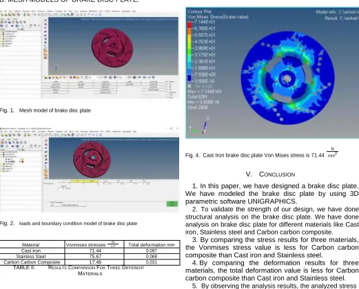
Cast iron 71.44 0.097
Stainless Steel 75.67 0.068
Carbon Carbon Composite 17.46 0.031
TABLE II. RESULTS COMPARISON FOR THREE DIFFERENT
MATERIALS
Fig. 4. Cast Iron brake disc plate Von Mises stress is 71.44
N
mm2
V. CONCLUSION
1. In this paper, we have designed a brake disc plate. We have modeled the brake disc plate by using 3D parametric software UNIGRAPHICS.
2. To validate the strength of our design, we have done structural analysis on the brake disc plate. We have done analysis on brake disc plate for different materials like Cast iron, Stainless steel and Carbon carbon composite.
3. By comparing the stress results for three materials, the Vonmises stress value is less for Carbon carbon composite than Cast iron and Stainless steel.
4. By comparing the deformation results for three materials, the total deformation value is less for Carbon carbon composite than Cast iron and Stainless steel.
Fig. 5. Stainless steel brake disc plate displacement is 0.068 mm
Fig. 6. Stainless Steel brake disc plate von mises stress is 75.44
N
mm2
values are less than their respective yield stress values. So our design is safe.
6. So we can conclude that as per our analysis using different materials for brake disc plate, Carbon carbon composite is best.
REFERENCES
[1] D. Majcherczak, P. Dufrenoy,´ and M. Na¨ıt-Abdelaziz, “thermal simula-tion of a dry sliding contact using a multiscale modelapplication to the braking problem,” Thermal stresses, Osaka (Japan), pp. 437–440, 2001.
[2] W. S. Chung, S. P. Jung, and T. W. Park, “Numerical analysis method to estimate thermal deformation of a ventilated disc for automotives,” Journal of Mechanical Science and Technology, vol. 24, no. 11, pp. 2189– 2195, 2010.
[3] F. Colin, A. Floquet, and D. Play, “Thermal contact simulation in 2-d an2-d 3-2-d mechanisms,” Journal of tribology, vol. 110, no. 2, pp. 247–252, 1988.
Sikender Mohsienuddin
Mohammad, Surya Lakshmisri , "SECURITY AUTOMATION IN INFORMATION TECHNOLOGY", International Journal of Creative Research Thoughts (IJCRT), ISSN:2320-2882, Volume.6, Issue 2, pp.901-905, June 2018,
Available at
:http://www.ijcrt.org/papers/IJCRT 1133434.pdf
Manishaben Jaiswal “
SOFTWARE QUALITY TESTING “ International Journal of
Informative & Futuristic Research (IJIFR) , ISSN: 2347-1697 , Volume 6, issue -2 , pp. 114-119 ,October-2018 Available at: http://ijifr.com/pdfsave/23-12-
Fig. 7. Carbon Carbon Composite brake disc plate displacement is 0.031 mm
Fig. 8. Carbon Carbon Composite brake disc plate von mises stress is 17.46
N
mm2
F. Talati and S. Jalalifar, “Analysis of heat conduction in a disk brake system,” Heat and mass transfer, vol. 45, no. 8, p. 1047, 2009.
A. Yevtushenko and R. Chapovska, “Effect of
time-generation and wear in transient axisymmetrical contact of sliding,” Archive of Applied Mechanics, vol. 67, no. 5, pp. 331–338, 1997.
S. Patra, Design and Modeling of Axial Micro Gas Turbine. PhD thesis, 2010.
W. Boehm and A. Muller,¨ “On de casteljau’s algorithm,” Computer Aided Geometric Design, vol. 16, no. 7, pp. 587–605, 1999.