Sujatha.CH(Assoc.prof)
Department of Electrical and Electronic Engineering, Gudlavalleru Engineering College, Gudlavalleru, (A.P.), India
Sravanthi.Kusam(M.tech)
Power electronics & Electrical Drives, Department of Electrical and Electronic Engineering, Gudlavalleru Engineering College, Gudlavalleru, (A.P.), India
Dr. K.Chandra shekar
Department of Electrical and Electronic Engineering, Rvr& jc college,ANU Guntur (A.P)
Abstract—
This paper presents the simulation of Shunt Active Power filter by using two different control schemes, Indirect current control technique and Synchronous detection technique by using ANN. These two control techniques are working under both balanced and unbalanced three phase voltage source conditions and it is feeding to a adjustable speed drive the torque speed characteristics of a motor is presented. Indirect current control technique is implemented under dynamic load condition and load balanced condition. The equal current distribution method of synchronous detection theory is used here to calculate the three phase compensating currents to be provided by the active filter. For calculating sequence currents neural network is used. Neural network is used for estimation of distorted waves, delay less harmonic filtering.
Keywords -- Power Quality, Shunt active filter, indirect current control, Synchronous detection technique
using ANN.
1. Introduction
The wide use of non-linear loads such as uninterrupted power supplies (UPS), adjustable speed drives (ASD), furnaces, and single phase computer power supplies etc cause power quality problems such as harmonic currents, poor power factor and voltage sag/swell increase in reactive power. There are several shunt active filtering algorithms developed. This paper presents the latest advanced techniques indirect current control and Synchronous detection technique of the Active filter; the three-phase reference supply currents are obtained using a closed loop PI controller. A Hysteresis PWM current controller is employed over the reference and sensed supply currents to generate gating pulses of IGBT’s of the Active filter. The control algorithm used in this is synchronous detection theory based on Equal current distribution, but this theory, in its original form, will not work under the condition of voltage distortion. This problem can be eliminated by sensing the source/load voltages/currents from which fundamental reference currents can be deduced. By using two control methods the THD values are compared and torque and speed variations for an adjustable speed drive with balanced and unbalanced voltage source are presented here. In this paper, simulation results of indirect current control technique and Synchronous detection technique are present.
2. Indirect current control
sa
u usb usc
Fig: 1 Control algorithm for indirect current control
Comparison of Average value of DC bus voltage (
v
dc) and reference value of dc bus voltage (v
dc*) of the AF results in a voltage error, which is fed to a PI controller as shown in figure.Here, proportional (
K
p) and integral gains (K
i) are so chosen, such that a suitable DC bus voltage response is achieved. The output of PI controller is taken as amplitude (I
sp*) of the reference supply currents.Now, Three-phase in-phase components of the reference supply currents are computed using their amplitude and in-phase unit current vectors derived in-phase with the supply voltages, and are given by
. . .
Where , and are in-phase unit current vectors and are derived as,
/ / /
Where is the amplitude of supply voltage and it is computed as
2/3 /
Hence from the above procedure, the three phase reference supply currents are computed.
Now the three-phase reference supply currents and sensed supply currents are given as inputs to hysteresis current controller which generates gating signals for IGBT’s of the AF.
A. Implementation of hysteresis based current controller
Upper switch on: (i* - i) > HB. Lower switch on: (i* - i) < HB.
The model of hysterisis controller, which is implemented in MATLAB for the current control purpose, is shown in below figure.
The simulation model for the indirect current control is shown in fig: 2. Three phase supply is used under both balanced and unbalanced conditions. Unbalanced case fifth and seventh harmonics are high. Third harmonic cuntent was zero because of tree phase. The input inductor, Dc bus capacitor used in AF is choosen as Lc=3.35mH,
C
dc= 1500µF. The torque speed a characteristic of adjustable speed drive is verified in with bothbalanced and unbalanced condition.
Fig: 2 Simulation model for Indirect current control scheme in SIMULINK environment.
3. Synchronous detection technique
Synchronous detection (SD) theory can work effectively under balanced as well as unbalanced source and load conditions because the compensating currents are calculated taking into account the magnitudes of per phase voltages. The synchronous detection method is applied to calculate compensating currents while the three phase source is feeding a highly non-linear load. The equal current distribution method of synchronous detection theory is used here to calculate the three phase compensating currents to be provided by the active filter.
The following assumptions are made in calculating the three phase compensating currents using equal current distribution method of synchronous detection algorithm: (i) Voltage is not distorted; (ii) loss in the neutral line is negligible. The equal current synchronous detection method shows a better profile of source side line current after compensation.
Assume the peak values of source currents are balanced after Compensation:
2
,
2
,
2
Where , and are real powers from each of the phases and , and are peak values of phase voltages in the three phases.
From the above equations
2
2
2
Then
The total average power
By rearranging
The reference active source currents are calculated as
2
2
2
Where
The compensating current is obtained as
In the control scheme, the fundamental positive sequence currents are being extracted. The reference currents can be obtained by subtracting the positive sequence current from the load current. The online extraction can be done by using Fourier integral or moving average filtering method. These methods involve a considerable delay for the calculation of Fourier coefficients. This delay can be reduced by the use of neural network filter. Applications of neural networks in power electronics are estimation of distorted waves, FFT analysis, on-line diagnostics, PWM techniques, delay less harmonic filtering, adaptive P-I close loop control etc. The control scheme applied in this work uses the neural network filter for online extraction of sequence currents.
Fig: 3 Multiple-input neuron
In the neuron the input signals pass through synaptic weights and collect in the summing node before passing through a transfer function at the output. A bias signal can be added in the summing node.
The interconnection of artificial neurons results in an artificial neural network (ANN). The ANN can generally be classified as feed forward and feedback types. In a feed forward network, the signals from neuron to neuron flow only in forward direction, where as in feedback network the signals flow in forward as well as backward direction. The examples of feed forward networks are perceptron, Adaline and Madaline and Back propagation network. The examples of feedback networks are Hopfield network and Boltzmann network. Extraction of negative sequence currents: For the extraction of sequence currents a three layer feed-forward back propagation neural network is used. The general structure of a feed-feed-forward back propagation network is shown below. The name "back propagation" comes from its characteristic training method. For extraction of sequence currents a three layer feed-forward back propagation neural network is used, with ten neurons in first layer (input layer) and ten neurons in second layer (hidden layer),three neurons in third layer (output layer). The transfer functions for all layers are purelin.
Fig: 4 Feed-Forward back propagation network
Training Data generation: For the extraction of sequence currents the required inputs are three phase currents, and the corresponding outputs. The required inputs and outputs are generated in MATLAB program. In the program the input Currents are initialized to zero, and incremented in steps. By taking one thousand samples in a cycle and arranging them in a vector of three rows, outputs also arranged in required vector size depends on the no of the outputs. The input vector size and output vector size must have same no of columns. The training data is generated for both balanced and unbalanced conditions. The number of the data required is depending on the network architecture and required error tolerance.
Training the Network: The training of the network was done with MATLAB program. The training data required the number of epochs, error and min_gradient. The number of epochs depends on the error, and architecture of the network. First, the weights are initialized to random numbers. After training the first data the weights are adjusted to the required outputs. The training is done for both balanced and unbalanced conditions. After training, the network is simulated with trained inputs. If the network errors are with in the predefined range then the architecture is suitable, other wise the network architecture must be changed. After successful training the network can also give the required outputs with unknown inputs. After training the architecture is converted to simulink block.
shows the inside view of a layer. The fig:8 shows the no of the neurons of a layer. Simulation model for the synchronous detection technique is shown in fig: 7.
Fig: 5 3Layer Feed-forward Neural Network Fig: 6 view of single Layer
Fig: 7 Simulation Model for Shunt active Filter for proposed Synchronous detection method
for providing harmonic compensation, load balancing and reactive power compensation. It can be clearly seen that by using Synchronous detection technique THD value is less compared to indirect current control technique.
Fig: 9 Indirect current control wave forms under balanced three phase (a) Supply voltage& current (b) load current (c) filter current
Fig: 11 power factor is unity for supply voltage and current
Fig: 12 speed & torque wave forms of adjustable speed drive for Indirect current control
Fig: 13 Indirect control FFT analysis for supply current
Fig: 15 Synchronous detection wave forms under balanced voltage. Three phase (a) supply voltage (b) supply current (c) Load current (d) output voltage (e) filter current
Fig: 17 speed & torque wave forms of adjustable speed drive (Synchronous detection)
Fig: 18 Synchronous detection wave forms under unbalanced voltage. Three phase (a) supply voltage (b) supply current (c) Load current (d) supply voltage after balancing (e) filter current
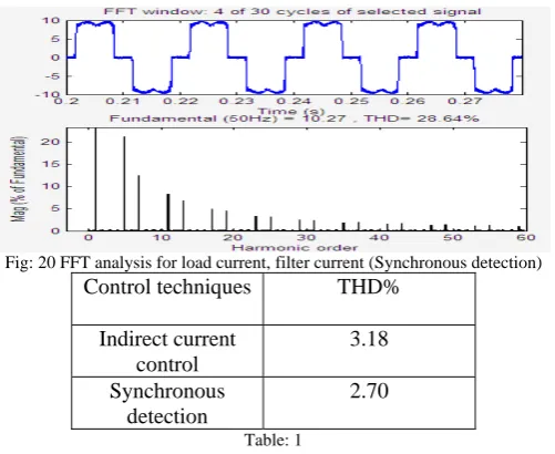
Fig: 20 FFT analysis for load current, filter current (Synchronous detection)
Control techniques THD%
Indirect current control 3.18 Synchronous detection 2.70 Table: 1
Table 1 shows that by using indirect current control the THD value is high compared to Synchronous detection technique. The harmonic content was eliminated in Synchronous detection technique is high.
5. Conclusion
In this paper, indirect current control and Synchronous detection methods using equal current division technique have been applied to a shunt active power filter to compensate for reactive and harmonic currents under balanced and unbalanced source voltage conditions. The simulation has been carried out in MATLAB/SIMULINK environment and power factor is unity for supply voltage, current.
6. References
[1] C.K.Duffey and R.P.Stratford,”Update of Harmonic Standard IEEE-519 IEEE Recommended Practices and
[2] Requirements for Harmonic control in Electric Power System,”IEEE/IAS Transactions,Nov. /Dec.1989, pp.1025-1034.
[3] Australian Standard (AS1359.31-1986), “Rotating Electrical machines –General Requirements,” 1986.
[4] uropean Standard IEC- 34-1(1983), “Rotating Electrical machines,” 1983.
[5] Annette von Jouanne and Basudeb (Ben) Banerjee, “Assessment of Voltage Unbalance,” IEEE Transactions on power
[6] delivery, Vol. 16, no. 4, Oct. 2001, pp. 782 – 780.
[7] F.Z.Peng, D.J.Adams, “Harmonic sources and filtering approaches-series/parallel, active/passive, and their combined
[8] power filters,” Conference Record of the IEEE 34th IAS Annual Meeting, Vol. 1, 3-7 Oct. 1999, pp. 448 – 455.
[9] L.M.Tolbert, H.D.Hollis, and P.S Hale, "Survey of Harmonics Measurements in Electrical Distribution Systems,” Industry
[10] Applications conference, 1996. 31st IAS Annual Meeting, Conference record of the 1996 IEEE.
[11] IEEE Task Force, “Effects of harmonics on equipment,” IEEE Transactions on Power Delivery, Vol. 8, Apr. 1993, pp.
[12] 672-680.
[13] IEEE Task Force, “The effects of power system harmonics on power system equipment and loads,” IEEE Transactions on
[14] Power Apparatus and Systems, vol. 104, Sept. 1985, pp. 2555-2563.
[15] Hugh Rudnick, Juan Dixon and Luis Moran, “delivering clean and pure power,” power energy magazine, IEEE, Vol. 1,
[16] No. 5, Sep-Oct 2003, pp. 32-40.
[17] Singh, K.Al-Haddad, A. Chandra, “A review of active filters for power quality improvement,” IEEE Transactions on
[18] Industrial Electronics, Vol. 46, No. 5, Oct.1999, pp.
[19] M. El-Habrouk, M.K.Darwish, P.Mehta, “Active power filters: a review,” Electric Power Applications, IEE Proceedings,
[20] Vol. 147, No. 5, Sept. 2000 pp. 403 – 413.
[21] NormanMarium, Ahsanul Alam, Senan Mahmod and Hashim Hizam,”Review of control strategies for power quality