http://www.sciencepublishinggroup.com/j/ijse doi: 10.11648/j.ijse.20180202.13
Development of High Efficiency and Cost Effective Energy
Generation Novel Technology
Zohrab Melikyan
*, Siranush Egnatosyan
“Heating Ventilation and Air Conditioning” Department, National University of Architecture and Construction of Armenia, Yerevan, Republic of Armenia
Email address:
*
Corresponding author
To cite this article:
Zohrab Melikyan, Siranush Egnatosyan. Development of High Efficiency and Cost Effective Energy Generation Novel Technology.
International Journal of Systems Engineering. Vol. 2, No. 2, 2018, pp. 52-56. doi: 10.11648/j.ijse.20180202.13
Received: August 16, 2018; Accepted: September 5, 2018; Published: October 4, 2018
Abstract:
During last, many years the electrical energy is generated in large Thermal Power Plants (TPP) and Nuclear Power Plants (NPP). Thermal Power Plants are the main electricity generating stations that are functioning based on the principle of thermal energy conversion into mechanical and finally into electrical energy. The noted conversion is accomplished by the condensation type of thermodynamic cycle that is called “Rankin” cycle. There are in use Co - generation heat and power plants too, which are functioning based on “Bryton” thermodynamic combined cycle. These plants are assigned for simultaneous generation and distribution of thermal and electrical energy. For this reason, they are more efficient. However, all mentioned cycles and conforming to them power plants serving for generation and distribution of large quantity of electricity from energy generating centralized stations to large number of consumers, which are located in significantly long distance from generating stations. The analysis of existing practice of use of mentioned types of electricity generating powerful centralized stations because of large losses of energy are not enough efficient and cost effective. For instance, the COP of electricity generating station, working by well-known Rankin cycle, makes only 30%, because about 70% of produced thermal energy should be lost to the surrounding environment for providing required conditions of electricity production. It is obvious that such big energy loses extremely pollute the environment, provoke global climate change and forces Governments adopting more forceful approaches to reduce carbon and other harmful gases rejections, increase efficiency of energy generation and improve environmental situation. For this reason, after having studied the potential possibilities of reduction of harmful gases rejections and increase of energy efficiency of electricity generation conventional mods the authors of this article became convinced in impossibility of assigned task and have decided to suggest novel and higher efficiency technology for electric energy generation. From this, point of view this article may become a guideline that can help to improve the present environmental and economic situations.Keywords:
Compressor, Expander, Air Receiver, Energy Producing Separate Equipment, Power, Pressure, Assemblage1. Introduction
The problems of generation, transportation and consumption of large quantity of electric energy without big difficulties became the main reason for inventing and using of different types of fossil fuels consuming powerful electric stations [1]. However, in spite of many advantages these electric stations are characterized by many disadvantages, which drastically decrease their effectiveness and create serious social and economic problems. The primary problems are the harmful toxic emissions created from the combustion of different fossil fuels such as coal, natural gas, sulfur dioxide
separate small equipment is the question of critical importance. As such, equipment can serve well-known reciprocated and turbo compressors, turbo expanders, electricity generators and various auxiliary equipment that are in production almost in all countries [3-5].
The primary emissions to surrounding environment from the combustion of fossil fuels or biomass are sulfur dioxide (SO2), nitrogen oxides (NOX), particulate matter (PM), carbon monoxide (CO), and greenhouse gases, such as carbon dioxide (CO2) and other environmentally harmful gases [2].
2. Developing of Electricity Generating
Station, Assembled From Energy
Producing Separate Small Equipment
The Figure 1 shows one of possible schemes of an electricity generating station, assembled from separate equipment.
Figure 1. Principal scheme of suggested electricity generating new station.
1-air compressor, 2- receiver of compressed air, 3- air pressure regulating gauge, 4-compresed air turbo expander’s feeding pipeline, 5- turbo expander of air, 6– reactive blades of air turbo expander, 7- electricity generator’s rotor driving shaft, 8- electricity generator, 9- condensate periodically removing automatic valve, 10- outlet of low pressure used air.
3. Operation of Energy Generating New
Station, Functioning by Novel
Technology
According to the suggested novel technology, the electrical energy generating station operates in the following way: the air compressor (1) compresses outside or inside air up to pressure Pexp.in and forces into the receiver (2) of compressed air. The volume of the receiver (2) depends on designed working regime of the station that conforms to the regime of generated electricity consumption, which in its turn depends on diagrams of energy consumers. The regulator (3) automatically controls the pressure of air in the receiver (2). The compressed air by the high-pressure air’s inlet tube (4) from the receiver (2) of compressed air is forced into the turbo expander (5) where it expands adiabatically up to the atmospheric pressure. Because of air expansion, the reactive blades (6) of turbo expander are rotating and spinning the shaft (7) of electric generator (8). Because of rotation, the electric generator (8) produces electricity, the specific quantity l, kJ/kg
of which is determined by the following equation [6-8]:
−
−
=
− k k
in out in
P
P
k
ZRT
l
1
. exp
. exp .
exp
1
1
(1)where:
Z=1.04-compressibility factor of air [9],
R= 287 J/(kgoC) - gas constant of air [10, 11],
Texp.in – initial temperature of air at the inlet of turbo - expander,
Pexp.in – initial pressure of the atmospheric air at the inlet of turbo-expander,
Pexp.out=1bar – pressure of the air at the outlet of the turbo-expander,
k =1.4 adiabatic or isentropic exponent for air [10]. Temperature of air at the inlet of turbo-expander Texp.in, can
be determined by the following equation [7-9]:
k k
in atm out air in
P
P
T
T
−
=
1
. exp . .
exp (2)
where:
Tair.out– outside air temperature, is adopted (for summer time: Tair.out=35+273=308oK, and for winter time: Tair.out = 273+(-19) =254oK [12]),
Patm=1bar - pressure of atmospheric air.
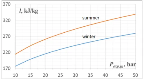
The results of calculations, made by equations (1) and (2) are shown on the Figure2 in form of diagrams.
Figure 2. Diagram of values of specific energy l, kJ/kg, produced in summer and winter periods, depending on pressure of air Pexp.in at the inlet of air
expander.
Figure 3. Power developed by turbo expander depending on quantity of expanded air.
The power, developed by turbo expander is determined by the equation as follows:
l
G
N
exp=
air (3)where:
Gair- quantity of air, expanded in the turbo expander, kg/s. The Figure 3 shows that power, produced by turbo expander depends on air quantity Gair, kg/s, which is supplied into the turbo expander. For example, capacity of the receiver, which is prescribed for screw type compressor ABT 500/2000 of “Fiak” company, is 500l, and the air productivity of the compressor is 2000 l/min or 0.04kg/s with pressure 10 bar [13] develops power Nexp the value of which, according to equation (3), makes:
56
.
8
214
04
.
0
exp
=
⋅
=
N
kW.4. Design of Electricity Station on
Example of a Low Rise Residential
House
The order of design of electricity station for a house or for other electricity consumer is the following:
1) Determination of electricity demand of the consumers; 2) Developing of electricity supplying and distributing scheme by all consumers;
3) Determination of characteristics of electricity producing separate small equipment and their selection;
4) Determination of energy-economic characteristics of designed electricity station.
An example of electric station designed for a 4 story residential house is shown in Figure 4.
Figure 4. Scheme of 4 story residential house with electricity generating new station and electricity supplying network.
1- electricity generating new station with transformer of the electric station, installed in the basement of 4 story residential house, 2- main electricity meter of the house, 3- main distributor of electricity, 4- electricity distributing main cord, 5-electricity distributors by stories (floors), 6-electricity meters by apartments, 7-distribution cords.
Automated receiver of compressed air controls the regime of operation of energy producing main small equipment like compressor, and high-pressure air turbo expander in the following way: a day is divided in three intervals of time with 8 hours duration each. During each interval, a process is executed. So in first 8 hours interval the compressor operates and fills up the receiver with compressed up to 10 bar air, afterwards the compressor automatically stops operating and second 8 hours interval starts, during of which through open automatic valve the high-pressure air expands and through air turbo expander paces from the receiver into atmospheric air and during second 8 hours electricity generation takes place. Taking into consideration above explanations the equation (1) can be transformed into the following one:
−
−
⋅
=
−
k k
in out in
P
P
k
ZRT
l
1
. exp . exp .
exp
1
1
τ
(4)
where:
τ= 8 hours or τ= 28800s – duration of interval of time when the station generates energy.
H
q
n
N
ap eldemst
. .
=
(5)where:
nap.=8- number of apartments of the building,
qel.dem. -electricity demands by each apartment per month, H=720 hours- duration of a month in hours.
According to diagram of Figure 5, the electricity demands of apartments with 4 residents each and 100m2 of surface makes qel.dem. =320kWh/month.
Figure 5. Normative consumption of electric energy in residential houses depending on number of residents and surfaces of apartments [14].
Substitute of above data in Eq. (5) and making calculations, will determine the following power, generated by the designed electric station:
56
.
3
720
320
8
=
⋅
=
stN
kW5. Tariff of Electricity, Generated by
Developed New Station
The tariff of energy is the average cost of 1 kW of energy, generated by electric station. It is determined by the following expression:
l
U
Y
K
T
fΣ
Σ
+
Σ
=
(6)where:
K
Σ
- total capital cost $, of the assembled power plant,U
Σ - annual operational cost of the power plant, $/year,
Y –capital investment’s payback period, which is selected to be equal to the life cycle duration of the station or any other period in case of which the cost of electricity supply T, $ becomes affordable for consumers and acceptable for investors, year,
l
Σ - quantity of energy, kWh/year, generated by electric station during one year.
The total capital cost
Σ
K
$, of the assembled power plant, is the sum of energy producing separate small equipment that is determined by the following expression:(
+
.exp+
.)
⋅
1
.
4
=
Σ
K
K
compK
turK
elgen (7)where:
Kcomp – cost of compressor with receiver, $, Ktur.exp - cost of turbo expander, $,
Kel.gen - cost of electricity generator, $,
1.4- electric station’s assembling and testing labor cost and in addition, extra expenditures factor.
5.1. Cost of Compressor and Receiver Is Defined by the Following Production
comp air comp comp
C
G
K
=
. (8)where:
Ccomp =2.92 $/(l/min) specific cost of compressor [15], Gair.comp- air productivity of compressor, depending on the quantity of air passing through the air expander. The air productivity of the compressor can be determined by the following production:
78
.
831
2
.
1
214
60
1000
56
.
3
60
1000
exp exp
.
⋅
=
⋅
⋅
=
⋅
=
air comp
air
l
N
G
ρ
l/minSubstitute of values Ccom and Gair.cominto (8) will obtain the capital cost of the compressor: Kcomp=2.92⋅831.78=$2429
5.2. Cost of Turbo Expander Is Defined by the Following Production
. exp . exp exp
.
C
N
K
tur=
(9)where:
C
exp - specific cost of turbo expander which according to [16] makes from $600 to $2300. The average specific cost makes 1450$/kW,N
exp – power of turbo expander, which according to (5) for the 8 apartments of 4 story house makes 3.56kW.Substitute of values Cexp and Nexp into (9) and making calculations will obtain the following capital cost of the turbo expander:
5162
$
56
.
3
1450
exp
.
=
⋅
=
tur
K
5.3. Cost of Electricity Generator
Because of absence of mass manufacturing of electric generators, which are similar to the electric generator which is invented in this article, the cost of electricity generator used in considered electric station is taken about the same as the cost of electric motor of the same 4 kW power, which is produced by the company “Energodrive” makes Kel.gen=$134 [17].
Substitute costs of all equipment in (7) will determine the following total capital cost
Σ
K
$, of the assembled power plant:(
2429
+
5162
+
134
)
⋅
1
.
4
=
$
10810
Total annual operational cost of considered power plant consists only of current repair cost of new electric station, which does not exceed 4%. For this reason, the current repair cost is neglected.
Quantity of energy, generated by electric station during one year makes:
24607
8
.
0
56
.
3
8640
.
=
⋅
⋅
=
=
Σ
l
τ
yearN
stm
op kWh/yearwhere:
year
τ
- total number of working hours of the station during a year,mop=0.8- coefficient of yearly operating hours of the station. Conformably, the tariff of energy, generated by suggested electric station makes:
018
.
0
24607
25
10810
≈
⋅
=
fT
$/kWhThe obtained value of the electricity tariff proves that developed electric station, based on suggested new technology is more efficient compared to existing in Armenia powerful centralized electric stations functioning by Rankin and combined cycles the electricity tariff of which makes 0.08$/kWh which in 4.44 times is lower, than the tariff of electricity, generated by centralized thermal power plants.
6. Conclusions
It is the first attempt to develop electricity station, assembled from energy producing small equipment that can become the first-born one in the range of new generation of electricity producing local facilities.
With successful start of use of suggested new technology new era of local, private and cheap electricity stations with very high efficiency and low cost of produced energy will start.
The tariff of electricity, produced by suggested novel technology will be fourfold lower.
The suggested new order of operation of energy producing small equipment can be useful for designers of electric stations.
The most valuable feature of developed new technology is the absence of natural fossil fuel use, which leads to preserving of environment from pollution and keeps stable climate.
The farther development of considered technology will shape a society of cheap energy consumers, cheap electric stations designers and cheap electricity producers that will spur development of economy of countries and will create
prosperous life.
References
[1] A Handbook of Energy Market Basics. “Energy Primer”.
Office of enforcement, Federal Energy Regulatory Commission(2015).
[2] Environmental, Health, and Safety Guidelines. “Thermal power plants”, Second public consultation (2017).
[3] Hanlon, P. C.: Compressor handbook. The McGraw-Hill Companies, (2001) ISBN 0-07-026005-2.
[4] Sarkar, A., Behera, D. K.: Wind Turbine Blade Efficiency and Power Calculation with Electrical Analogy. International Journal of Scientific and Research Publications, Volume 2, Issue 2, February, (2012) ISSN 2250-3153.
[5] Giampaolo, T.: Gas turbine handbook: Principles and practices, 3rd edition, Fairmont press, (2006) ISBN 0-88173-515-9. [6] Melikyan, Z.: A Novel Technology for Generation of
Electricity and Cold by Using Energy Potential of Transmission Line’s. Journal of Energy and Power Engineering, 9, (2015) pp.852-859 doi: 10.17265/1934-8975/2015.010.003. [7] Rajput, R. K.: Engineering Thermodynamics. Laxmi
publications, Third Edition, (2007) ISBN: 978-0-7637-8272-6. [8] Moran, M. J., Shapiro, H. N.: Fundamentals of Engineering Thermodynamics. John Wiley & Sons Ltd, The Atrium, Southern Gate, Chichester, West Sussex PO19 8SQ, England, (2006) ISBN-13 978-0-470-03037-0.
[9] Litvin, L. M.: Technical Thermodynamics. Textbook for institutions of higher education. Gosenergoizdat, Moscow- Leningrad, (1963) 312p.
[10] Al-Shemmeri, T.: Engineering Thermodynamics. Ventus Publishing ApS., (2010) ISBN 978-89-7681-670-4.
[11] Cimbala, J. M.: The Ideal Gas Constant. Penn State University (2014).
[12] “Construction Climatology” Construction Norms of Republic of Armenia II-7.01-2011.
[13] https://www.fiak.ru/upload/medialibrary/e9e/e9eef8493f709d2 6726aa52bf166db32.pdf.
[14] http://www.sahen.elektra.ru/page.php?id=160.
[15] https://www.fps-compressors.com/index.php/en/brands-2/test/ 115-price-list.
[16] http://www.gaselectricpartnership.com/SwRI%20WHR%20 gas % 20electric_2009.pdf.

![Figure 5. Normative consumption of electric energy in residential houses depending on number of residents and surfaces of apartments [14]](https://thumb-us.123doks.com/thumbv2/123dok_us/9553242.1484197/4.595.46.289.210.351/normative-consumption-electric-residential-depending-residents-surfaces-apartments.webp)
