Bilateral Teleoperation Control for Improving Transparency
in Stiff Environment with Time Delay
M. Azadegan*, S. Ozgoli*(C.A.) and H. D. Taghirad**
Abstract: This paper proposes a new bilateral control scheme to ensure the both
transparency and robust stability under unknown constant time delay in stiff environments. Presented method guaranties system performance and robust stability while the transition between soft and stiff environments occur. Presented framework is a combination of adaptive sliding mode controller and adaptive impedance controller, in which an online estimation of environment impedance is performed to be used as desired impedance in master side. Numerical simulations under different conditions such as constant and time-varying delays and obstructed environments are provided to verify the theoretical results. Transition between soft and stiff environments is also considered. Finally, the proposed method is compared with a recent work in this field.
Keywords: Adaptive Impedance Control, Adaptive Sliding Mode Control, Teleoperation, Transparency.
1 Introduction1
Teleoperated systems are now being used in several applications such as nuclear experiments [1], telesurgery [2], micro manipulation [3] and space robotics [4]. One of the most important challenges in teleoperation systems is time delay [5]. Teleoperation systems are subjected to the time delay caused by communication-channels. Nowadays teleoperation systems which are connected through the internet experience the time delay created by this network. Internet has unknown time-varying delay which results in reduced stability and control performance of the closed-loop system over it [6]. To stabilize the system under communication delay, scattering theory [7] and wave variable [8, 9] methods have been proposed, however these methods cannot ensure acceptable level of transparency in case of time-varying delay. Ideal transparency is defined as the equivalence between the impedance felt by operator and the impedance of the environment [10]. Mentioned methods do not have such characteristic.
The other problem to be addressed in teleoperation systems is the system failure in tracking the position while interacting with stiff (obstructed) environments,
Iranian Journal of Electrical & Electronic Engineering, 2014. Paper first received 10 Nov. 2013 and in revised form 10 Mar. 2014. * The Authors are with the Electrical and Computer Engineering Department, Tarbiat Modares University, Tehran, Iran.
** The Author is with the Electrical and Computer Engineering Department, K.N. Toosi University of Technology, Tehran, Iran. E-mails: [email protected], [email protected] and [email protected].
which may lead to instability [11]. In [12] an adaptive impedance control, and in [13] a time varying wave-based method has been proposed to achieve position tracking in stiff environments. In [14] an observer-based sliding mode impedance controller has been proposed to guarantee robust tracking under unknown constant time delay. In [15] a fuzzy singular perturbation point of view is obtained to model the teleoperation system and control it. Researchers in [16] have proposed an adaptive controller based on MRAC and a feed-forward compensator parallel to the plant, such that the stability has been ensured for a wide range of time delays; nevertheless interaction with stiff environment has not been considered. In [17], an adaptive-robust controller has been designed for teleoperation systems in presence of dynamic uncertainty and constant time delay which has also considered a restricted range of uncertainties in the environment stiffness. Another work on time delay can be found at [18] where they have used a friction compensator with impedance controller.
Most control frameworks for bilateral teleoperation are designed to achieve both stability and transparency; effectiveness of these controllers generally depends on the dynamics of the environment which is often unknown or variable. So far, researchers have employed position, velocity and force or impedance information to propose a variety of control schemes. However, none of these controllers can ensure both stability and transparency independent of time-varying delay and also dynamics of the environment. This is due the fact that there is a trade-off between the aforementioned goals [5, 19].
In this paper, a new architecture for bilateral teleoperation which is composed of a Sliding Mode Controller (SMC) at the slave side and an adaptive impedance controller at the master side is proposed. Using the sliding mode concept, the proposed architecture will become robust to time-varying delay and uncertainties in the environment dynamics. Furthermore, the adaptive impedance controller is designed to achieve the environment impedance at the master side, so that the operator feels a correct sense of the environment. It has been shown that the proposed structure, unlike many other methods, has good performance in presence of time-varying delay, while moving in stiff environments, and in addition, while transitioning between soft and stiff environments.
This paper is organized as follows: robot models are given in Section 2. In Section 3, problem formulation and the control law design procedure has been discussed. Simulation results and validation of the proposed structure along with the comparison with some other recent methods are presented in Section 4. Section 5 provides the summary and concluding remarks.
2 Modeling
Since the master and slave robots are considered to act almost linearly, they are modeled using a linear mass-damper system, as shown in Fig. 1.
In Fig. 1 um and um are control signals, fh is the force applied to the master side by the operator, and fe is the force exerted on slave robot from the environment. This model is very common in the literature and has been used in several articles [20-22]. Dynamics of the master and slave robots are then given by:
( ) ( ) ( ) ( )
m m m m m h
M v t +B v t =u t +f t (1)
( ) ( ) ( ) ( )
s s s s s e
M v t +B v t =u t −f t (2)
where M denotes inertia, B is the damping coefficient, v stands for velocity, and subscripts 'm' and 's' denote the master and the slave, respectively. Using mechanical impedance concept in frequency domain, the relation between forces and velocities is given by:
*
h h h m
F =F −Z V (3)
e e s
F =Z V (4)
where capital letters denote the Laplace transformation,
Zh and Ze are the human and environment impedances and Fh* is the operator exogenous force.
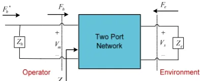
The main control objective at the master side is to
provide the entire environment’s impedance to the operator. In other words, achieving the ideal transparency is desired. To design the controller for the master side, the teleoperation system is considered as a two port network, as shown in Fig. 2.
To provide a correct sense of environment to the operator (transparency), the information of position and force are not enough individually [23]. Therefore, the impedance controller at the master side works well to achieve:
t e
Z =Z (5)
where Ze is the impedance of the environment and Zt is the equivalent impedance at the master side that operator feels:
h t
m F Z
V
= (6)
From Eqs. (5) and (6), desired dynamics for the master is given by:
h m e
F =V Z (7)
It is assumed that the slave robot is in contact with the environment modeled as a mass-spring-damper system with stiffness Ke, viscosity Be, and mass Me. So that Eq. (4) and (7) would become:
e e s e s e s
f =M v +B v +K x (8)
h e m e m e m
f =M v +B v +K x (9)
Based on the assumptions mentioned above, in the next section design procedure of the controller is provided.
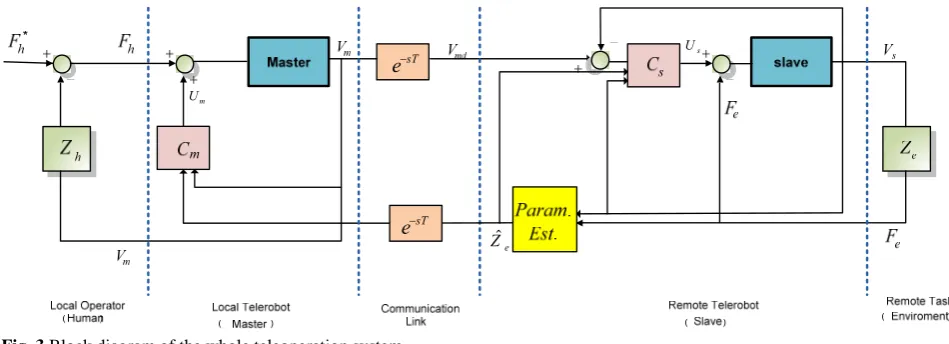
3 Controller Design
Controller structure is assumed to be as depicted in Fig. 3. The details are provided as follows.
3.1 Adaptive Impedance Controller (Master Side)
Theorem 1. Provided that the environment
impedance parameters are known, the control law given by
( ) ( )
m m e m m e m e m
u = M −M v + B −B v −K x (10)
where xm denotes position of the master, ensures a) Desired impedance at the master side is equal to the impedance of environment; b) Force tracking would be achieved if the position tracking would be confirmed.
Proof. a) Substituting Eq. (10) in Eq. (1) and using Laplace transformation yields
Fig. 2 Teleoperation system as a two port network. Fig. 1 Dynamics of the master and slave robots.
e
Zˆ
sT
e−
sT
e−
m
U
s
U
Fig. 3 Block diagram of the whole teleoperation system.
e h
m s
F F
V =V (11)
Using the definitions in Eqs. (4) and (7), we have
t e
Z =Z (12)
b) If the position tracking is ensured at the slave side, i.e. if
. sT
s m
v =v e− (13)
in which T is the channel delay from master to slave, then
. sT e h
f =f e− (14)
which means complete force tracking has been achieved.
Now in order to implement the controller given by Eq. (10), the environment parameters (Ke, Be, Me) should be estimated and the control law needs to be adapted accordingly, since the mentioned parameters are all unknown and variable. This is done by measuring the slave position, xs and the force exerted on robot from the environment fe.
Transfer function is obtained by applying the Laplace transformation on Eq. (8):
s
2
e e e e
( ) 1
( )
X s
F s = M s +B s K+ (15)
Discretization of Eq. (15) with sampling time Ts (using Zero order hold method), gives:
s 1 0
2
e 1 0
( ) ( )
X z b z b
F z z a z a
+ =
+ + (16)
The Recursive Least Square (RLS) algorithm is used to estimate the parameters a0, a1, b0and b1. Afterwards the impedance parameters can be achieved by the inverse conversion. Using the estimated values
ˆ ˆ ˆ
(M B Ke, e, e) in Eq. (10), control signal for the master robot becomes:
ˆ ˆ ˆ
( ) ( )
m m e m m e m e m
u = M −M v + B −B v −K x (17)
Notice that except some rare changes which can be modeled by step function, the impedance of the environment is assumed to be constant in time. So we can assume Z tˆe( )=Z t Tˆe( − )=Zˆe.
Applying Eq. (17) to the master side, we would have an adaptive impedance control law that provides actual remote impedance characteristics by online estimation, so that the human operator receives an accurate impression while interacting with the virtual environment.
In the next section, designing the controller for the slave side is presented.
3.2 Sliding Mode Controller (Slave Side)
SMC is used at slave side due to its robustness against the uncertainties which includes the uncertainty in parameters and time delay. Design details have been given in the following theorem.
Theorem 2. If K > η.Ms, then the following slave controller guarantees exponential convergence of position tracking error.
ˆ ˆ
( )
ˆ
sat( ) s
s s hd e md e md
e s s e
M
u M e f B v K x
M
S
B v f K
λ
φ
= + − −
+ + −
(18)
where K > 0 is a constant, sat(.) is the saturation function and φ is the thickness of the boundary layer selected such that the chattering phenomenon is reduced.
In addition, S(t) is the sliding surface considered as follows:
( ) ( ) ( ) , 0
S t =e t +λe t λ> (19)
in which, λ is a strictly positive constant and e is defined as the tracking error between the slave and delayed master position:
( ) m( ) s( )
e t =x t T− −x t (20)
Proof. Consider the following Lyapunov function candidate:
2
1 2
V = S (21)
It is clear that V is a positive definite function; taking its derivative with respect to time and substituting Syields
[( md s) ]
V=SS=S v −v +λe (22)
in which vmd(t) = vm(t - T). Substituting Eq. (18) into Eq.
(2) yields:
1 ˆ ˆ
( )
ˆ
1
( ( ))
s hd e md e md
e
s
v e f B v K x
M S Ksat M λ φ = + − − + − (23)
Substituting this equation into Eq. (22) we get:
1 ˆ ˆ
[( ( ( )
ˆ
1
( sat( ))) ]
md hd e md e md
e
s
V S v e f B v K x
M S K e M λ λ φ = − + − − − + (24)
On the other hand, from Eq. (9) we have
ˆ ˆ ˆ
hd e md e md e md
f −B v +K x =M v (25)
Combining Eqs. (24) and (25), yields: 1
( ( ( sat( )))
1
( ( sat( )) md md
s
s
S
V S v v K
M S S K M φ φ = − − = − (26)
Choosing the gain as K > η.Ms, we have
sat(S) 0
V η S
φ
< − <
(27)
Thus, Eq. (21) is a Lyapunov function. By choosing a proper value for gain, position tracking is guaranteed independent of the amount of time delay.
3.3 Modification of the SM Controller
The proposed SM controller uses an online estimation of the environment impedance. So, before the convergence of estimations, the tracking error would be large. To cope with this fact, the gain of the switching term in Eq. (18) should be adapted accordingly.
Substituting fˆe instead of fe in Eq. (22) and
repeating the same procedure as before, the limitation on gain K is achieved as follows:
ˆ .
ˆ ˆ ˆ
.
s e e
s e s e s e s e
K M f f
M M v B v K x f
η
η
> + −
= + + + − (28)
in which K Bˆe, ˆe and Mˆe are estimated values of the environment impedance, and fe is the force exerted by
the environment on the slave, which can be measured by a force sensor.
4 Simulations
In this section, the performance of the proposed controller is investigated via simulations. Different conditions such as constant and varying time-delay, moving in stiff environment, and transitioning from a free or soft environment to a stiff one are considered. Numerical values are considered as follows:
5, 1.5 , 0.1, 0.5,
0.1, 1, 10,
1, 10 , 500
0.1 , 1
s s m m
h h h
e e e
M B M B
M B K
M B K
φ η = = = = = = = = = = = = (29)
These values are common in the literature, e.g. [13].
4.1 Offline Estimation, Constant Time Delay
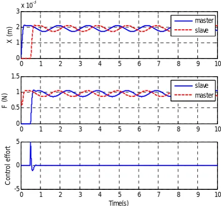
First assume that we have access to the remote environment, so parameters of the environment can be estimated offline. Figs. 4 and 5 show the simulation results in presence of the constant time delay and stiff environment. It can be seen from Fig. 4 that applying the proposed controller results in achieving the position and force coordination goals. Fig. 5 provides a comparison with [13]. It is shown that the presented structure in [13] diverges, despite the simulations are done in the same condition as proposed method. In other words, this controller is not capable of stabilizing the system in an environment with 500 N/m stiffness. This is due to the fact that researchers in [13] have considered some restrictive assumptions on the upper bound of environment’s stiffness or delay. Several other papers have also made the same restrictive assumption [24-27] which is released in current paper.
0 1 2 3 4 5 6 7 8 9 10
0 1 2 3x 10
-3
X (
m
) masterslave
0 1 2 3 4 5 6 7 8 9 10
0 0.5 1 1.5 F ( N ) slave master
0 1 2 3 4 5 6 7 8 9 10
-5 0 5 Time(s) C ont ro l ef fo rt
Fig. 4 Position and force of robots with proposed structure (mean(T) = 500 msec, Ke = 100 N / m).
4.2 Time-Varying Delay
As the internet is the most common communication channel, confronting with its unknown time-varying delay is inevitable. Fig. 6 shows the position and force of robots in presence of a time varying delay with mean value of 500 msec, and variance of 100 msec. It can be seen that the system has acceptable performance, even with time-varying delay.
A comparison with the presented method in [13] is depicted in Fig. 7. As it can be seen, the system performance is degraded. In general, every method based on wave variable [9, 13 and 28]) has the deficiency of showing undesirable performance or instability under time-varying delay; although all of the mentioned methods ensure stability and good performance of the system under constant time delay.
4.3 Obstructed Environment
The third condition in which the system performance is investigated is the collision of the slave robot with an obstacle while moving in a free environment. The
environment is modeled as a stiff wall (Ke = 500 N/m) located at xs = 0.02 m with a reaction force given by:
s s s
10V 500(X 0.02) if X 0.02 m 0 N otherwise
e
f = ⎨⎧− − − ≥
⎩ (30)
Human action is modeled as a constant force source for the first 2 seconds. After that this force is modeled as follows:
m m
10 0 2 20V 25X 2
h
N if t s
i f
f t s
≤ ≤ ⎧
= ⎨− − ≥
⎩ (31)
The system response is depicted in Fig. 8. Several proposed methods such as [29, 30] and [31] result in instability or bad performance in the case that a collision between the slave robot and wall occurs. Due to this, we will not provide comparison figures and just the results of the proposed method are given here. Fig. 8 shows that the proposed structure in this paper ensures not only stability but also good tracking performance.
Once the slave retrieves from the wall, both master and slave positions converge to the desired values.
0 1 2 3 4 5 6 7 8 9 10
-6 -4 -2 0 2 4x 10
-3
X (
m
)
X
m
X
s
0 1 2 3 4 5 6 7 8 9 10
-1 -0.5 0 0.5 1
F (
N
)
Time (s)
F
e
F
h
Fig. 7 Position and force of robots with structure [13] (mean(T) = 500 msec,var(T) = 100, Ke = 100 N / m).
0 1 2 3 4 5 6 7 8 9 10
-0.1 -0.05 0 0.05 0.1
X (m
)
Xm
Xs
0 1 2 3 4 5 6 7 8 9 10
-50 0 50
F (N
)
Time (s)
master slave
Fig. 5 Simulation result for the structure of [13] (mean(T) = 500 msec, Ke = 100 N / m).
0 1 2 3 4 5 6 7 8 9 10
0 1 2 3x 10
-3
X (
m
) masterslave
0 1 2 3 4 5 6 7 8 9 10
0 0.5 1 1.5
F (
N
)
slave master
0 1 2 3 4 5 6 7 8 9 10
-2 0 2 4
Time(s)
C
o
n
tr
o
l e
ffo
rt
Fig. 6 Position and force of robots with proposed structure (mean(T) = 500 msec,var(T) = 100, Ke = 100 N / m).
0 0.5 1 1.5 2 2.5 3
-0.02 0 0.02 0.04
X (
m
)
master slave
0 0.5 1 1.5 2 2.5 3
-10 0 10 20
F (
N
)
slave master
0 0.5 1 1.5 2 2.5 3
-100 -50 0 50
Time(s)
C
o
n
tr
o
l e
ffo
rt
Fig. 8 Position and force of robots with proposed structure, obstructed environment (T = 200 msec).
4.4 Transitioning Between Soft and Stiff Environment
Transitioning between soft and stiff environment is the last condition in which the system performance is verified. In this case, the environment is modeled as two surfaces with stiffness (Ke = 100 N/m) and (Ke = 500
N/m) which are located at xs = 0.005 m and xs = 0.01 m respectively. So the reaction force is given by:
10V 500(X 0.01) if X 0.01 m
s s s
f 10V 100(X 0.005) if 0.005 X 0.01 m
e s s s
0 N otherwise
− − − ≥
= − − − ≤ <
⎧ ⎪ ⎨ ⎪ ⎩
(32)
The human force is modeled as follows:
*
*
3 if 0 3 6 if 3 5
0.2 sin( )
h h
h
f f N t s
N t s
wt f
≤ ≤ ⎧
= + ⎨
≤ ≤ ⎩
=
(33)
It is assumed that the reference inputfhis a summation of step and sine functions. This assumption is made to show the behavior of the system and effect of time-delay at both transient and steady state responses. As can be seen in Fig. 9, good position coordination has also been achieved.
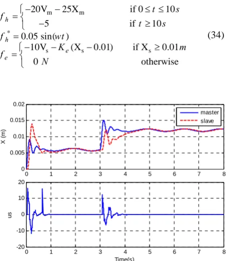
Now the performance of the system is investigated under the condition when there is no prior knowledge about the impedance of the remote environment and online estimated values are used in control inputs. For the sake of simplicity, it is assumed that only the stiffness of the environment is variable so only the stiffness parameter should be estimated. The human and environment forces are considered to be:
*
m m
s s s
20V 25X if 0 10
5 if 10 0.05 sin( )
10V (X 0.01) if X 0.01
0 otherwise h
e h
e
f t s
t s
wt
K m
f
f
N
− − ≤ ≤
⎧
= ⎨ − ≥
⎩ =
− − − ≥
=⎧⎨ ⎩
(34)
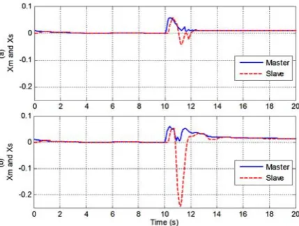
The simulation results for different values of Ke are shown in Figs. 10-12. Moreover, performance of the system while transitioning between soft and stiff environment occurs is verified in Fig. 13. As shown in these figures, though the system remains stable and achieves good tracking performance after a few seconds, increasing Ke results in increased transient response error which is better to be reduced. Fig. 14 indicates that with modification of the proposed controller, this purpose is attained as well.
10 Conclusions
This paper presents a new control framework for teleoperation systems which is composed of an adaptive impedance controller at the master side and an adaptive sliding mode controller at the slave side. This structure provides both stability and transparency even when the slave robot collides with an obstacle or transitioning
0 5 10 15 20 25 30
-0.02 0 0.02 0.04 0.06
Xm v
s
. Xs
0 5 10 15 20 25 30
0 20 40 60
Time(s)
Ke
Master
Slave
Fig. 10 Position of robots and estimated parameter with proposed structure, obstructed environment (Ke = 50 N / m).
0 5 10 15 20 25 30
-0.02 0 0.02 0.04 0.06
X
m v
s
.
X
s
0 5 10 15 20 25 30
0 100 200 300 400
Time(s)
Ke
Master Slave
Fig. 11 Position of robots and estimated parameter with proposed structure, obstructed environment (Ke = 150 N / m).
0 1 2 3 4 5 6 7 8
0 0.005 0.01 0.015 0.02
X (
m
)
0 1 2 3 4 5 6 7 8
-20 -10 0 10 20
us
Time(s)
master slave
Fig. 9 Position and force with proposed structure, transitioning between soft and stiff environment (mean(T) = 200 msec, var(T) = 100 msec).
0 5 10 15 20 25 30 -0.3
-0.2 -0.1 0 0.1
X
m
vs.
Xs
0 5 10 15 20 25 30
0 500 1000 1500
Time(s)
Ke
Master Slave
Fig. 12 Position of robots and estimated parameter with proposed structure, obstructed environment (Ke = 500 N / m).
0 5 10 15 20 25 30 35 40
-0.01 -0.005 0 0.005 0.01 0.015 0.02 0.025 0.03
Xm
vs.
X
s
Time (s)
Master Slave
Fig. 13 Position of robots with proposed structure, transitioning between soft and stiff environment (Ke = 100 to 500 N / m).
Fig. 14 Position of robots with modified proposed structure, obstructed environment, (Ke = 500 N / m).
between soft and stiff environments in the presence of constant and unknown time-varying delay occurs. Stability proof has been provided and several practical scenarios have been considered through the simulations which are performed on the robot model with the proposed control structure. Simulation results indicates the good performance of the proposed strategy under different conditions where many other structures presented in literature become unstable or leads to poor system performance, due to their limitation on the amount of the time-delay or the impedance of the environment.
References
[1] W. Wang and K. Yuan, “Teleoperated
manipulator for leak detection of sealed radioactive sources”, Proc. IEEE Int. Conf.
Robotic. Autom., Vol. 1, No. 1, pp. 1682-1687, 2004.
[2] P. Berkelman, P. Cinquin, E. Boidard, J. Troccaz, C. Letoublon and J. M. Ayoubi, “Design, control and testing of a novel compact laparoscopic endoscope manipulator”, Proc. of the Institution
of Mechanical Engineers, Part I: Journal of Systems and Control Engineering, Vol. 217, No. 4, pp. 329-341, 2003.
[3] N. Bhat and W. J. Kim, "Precision force and position control of an ionic polymer metal composite”, Proc. of the Institution of Mechanical
Engineers, Part I: Journal of Systems and Control Engineering, Vol. 218, No. 6, pp. 421-432, 2004.
[4] N. Kubota, "Human-friendly tele-operation for robot partners”, Proc. of the Institution of
Mechanical Engineers, Part I: Journal of Systems and Control Engineering, Vol. 225, No. 3, pp. 361-366, 2011.
[5] E. J. Rodriguez-Seda, D. Lee and M. W. Spong, “Experimental comparison study of control architectures for bilateral teleoperators”, IEEE
Trans. on Robotics, Vol. 25, No. 6, pp. 1304-1318, 2009.
[6] E. Slawinski, J. F. Postigo and V. Mut, “Bilateral teleoperation through the internet”, Robotics and
Autonomous Systems, Vol. 55, No. 3, pp. 205-215, 2007.
[7] R. J. Anderson and M. W. Spong, “Bilateral control of teleoperators with time delay”, Proc.
IEEE Conf. Decision Control, Austin, TX, pp. 167-173, 1988.
[8] G. Niemeyer and J. J. E Slotine, “Stable adaptive teleoperation”, IEEE Journal of Oceanic
Engineering, Vol. 16, No. 1, pp.152-162, 1991. [9] Y. Ye and P. X. Liu, “Improving trajectory
tracking in wave-variable-based teleoperation”,
IEEE/ASME Trans. on Mechatronics, Vol. 15, No. 2, pp. 321-326, 2010.
[10] D. A. Lawrence, “Stability and transparency in bilateral teleoperation”, IEEE Trans. on Robotics
and Automation, Vol. 9, No. 5, pp. 624-637, 1992.
[11] N. Chopra and M. W. Spong, “On position tracking in bilateral teleoperation”, Proc. of the
American Control Conference, Boston, 2004. [12] L. J. Love and W. J. Book. “Force reflecting
teleoperation with adaptive impedance control”,
IEEE Trans. on systems, Man and Cybernetics, Vol. 34, No. 1, pp. 159-165, 2004.
[13] E. J. Rodriguez-seda and M. W. Spong, “A time-varying wave impedance approach for transparency compensation in bilateral
teleoperation”, IEEE/RSJ International
Conference on Robots and systems, pp. 4609-4615,2009.
[14] L. G. Garcia-Valdovinous, V. Parra-Vega and M.A. Arteaga, “Observer-based sliding mode impedance control of bilateral teleoperation under constant time delay”, Robotics and Autonomous
Systems Vol. 55, No. 8, pp. 609–617, 2007. [15] R. Wang, C. Xia, W. Gu and K. Li, “Fuzzy
singularly perturbed model and stability analysis of bilateral teleoperation system”, 30th Chinese
Control Conference, pp. 3664-3668, 2011. [16] K. Hosseini-suny, H. Momeni and F.
Janabi-Sharifi, “A modified adaptive controller design for teleoperation systems”, Robotics and
Autonomous Systems, Vol. 58, No. 5, pp. 676-683, 2010.
[17] A. Shahdi and S. Sirouspour, “Adaptive/robust control for time-delay teleoperation”, IEEE
Trans. on Robotics, Vol. 25, No. 1, pp. 196-205, 2009.
[18] A. Monemian Esfahani, S. M. Rezaei and M. Zareinejad, “Robust Impedance Control of a Teleoperation System With Friction Compensation Under Time Delay”, ASME 2009
International Mechanical Engineering Congress and Exposition, Vol. 10, pp. 199-207, 2009. [19] P. Arcara and C. Melchiorri, “Control schemes
for teleoperation with time delay: a comparative study”, Robotics and Autonomous Systems Vol. 38, No. 1, pp. 49-64, 2002.
[20] M. Shasadeghi, H. R. Momeni, “A new
impedance and robust adaptive inverse control approach for a teleoperation system with varying time delay”, Sci China Ser E-Tech Sci, Vol. 52, No. 9, pp. 2629-2643, 2009.
[21] B. Willaert, B. Corteville, D. Reynaerts, V. Brussel and E. B. V. Poorten. “Bounded environment passivity of the classical position-force teleoperation controller”, IEEE/RSJ
International Conference on Intelligent Robots and Systems, pp. 4622-4628, 2009.
[22] V. T. Minh and F. B. MohdHashim, “Time forward observer based adaptive controller for a
teleoperation system”, International Journal of
Control, Automation, and Systems, Vol. 9, No. 3, pp. 470-477, 2011.
[23] K. Hashtrudi-Zaad and S. E. Salcudean,
“Analysis and evaluation of stability and performance robustness for teleoperation control architectures”, Proc. IEEE International
Conference on Robotics and Automation, pp. 3107-3113, 2000.
[24] R. Lin and T. Namerikawa, “Robust control of master-slave robot system considering environmental uncertainties”, Proc. of the 2005
IEEE/ASME Int. Conf. on Advanced Intelligent Mechatronics, Monterey, CA, pp. 1299-1304, 2005.
[25] A. Haddadi and K. Hashtrudi-Zaad, “Delay-robust transparent bilateral teleoperation control design”, IEEE/RSJ Int. Conf. on Intelligent
Robots and Systems, pp. 438-444, 2008.
[26] C. C. Hua and X. P. Liu, “Delay-dependent stability criteria of teleoperation systems with asymmetric time-varying delays”, IEEE Trans. on
Robotics, Vol. 26, No. 5, pp. 925-932, 2010. [27] K. C. Walker, Y. K. Pan and J. Gu, “Bilateral
teleoperation over networks based on stochastic switching approach”, IEEE/ASME Trans. on
Mechatronics, Vol. 14, No. 5, pp. 539-554, 2009. [28] K. Kawashima, K. Tadano, W. Cong and G.
Sankaranarayanan, “Bilateral teleoperation with time delay using modified wave variable based controller”, IEEE International Conference on
Robotics and Autom., Japan, pp. 1114-1119, 2009.
[29] T. Namerikawa, “Bilateral control with constant feedback gains for teleoperation with time varying delay”, Joint 48th IEEE Conference on
Decision and Control and 28th Chinese Control Conference, China, pp. 7527-7532, 2009.
[30] L. Bate, C. D. Cook and L. Zheng, “Reducing wave-based teleoperator reflections for unknown environments”, IEEE Trans. on Industrial
Electronics, Vol. 58, No. 2, pp. 392-397, 2011. [31] H. Kawada and T. Namerikawa, “Bilateral
control of nonlinear teleoperation with time varying communication delays”, 2008 American
Control Conference, Washington, USA,pp. 189-194, 2008.
Masoumeh Azadegan was born in Babol, Iran in 1985. She received the B.Sc. degree in Control Engineering from K.N. Toosi University of Technology in 2007, M.Sc. in Control Engineering from Tarbiat Modares University, Tehran, Iran in 2010. She is currently pursuing a Ph.D. degree in Control Engineering from Tarbiat Modares University. Her research interests include teleoperation,
networked control systems, time-delayed systems and markovian jump systems.
Sadjaad Ozgoli was born in Tehran, Iran, in 1974. He received the B.Sc. and M.Sc. degrees in electrical engineering from Sharif University of technology, Tehran, Iran, in 1997 and 1999 respectively, and Ph.D. degree in electrical engineering from the K.N.Toosi University of Technology, Tehran, Iran, in 2005. At 2006 he has been with the Engineering department at Leicester University, Leicester, UK, as a Postdoctoral researcher. Since June 2007, he has been with the Department of Control Engineering, Faculty of Electrical Engineering at Tarbiat Modares University, Tehran, Iran, where he is an Assistant Professor now. Dr. Ozgoli is the officer of IEEE Iran section membership development committee since October 2011. His current research interests include robust and nonlinear control applied to biologic and mechatronic systems. His publications include a book, and more than 30 papers in international Journals and conference proceedings.
Hamid D. Taghirad has received his B.Sc. degree in mechanical engineering from Sharif University of Technology, Tehran, Iran, in 1989, his M.Sc. in mechanical engineering in 1993, and his Ph.D. in electrical engineering in 1997, both from McGill University, Montreal, Canada. He is currently a Professor and the dean of the Faculty of Electrical Engineering, and the Director of the Advanced Robotics and Automated System (ARAS) at K.N. Toosi University of Technology, Tehran, Iran. He is a senior member of IEEE, the chairman of IEEE control system chapter in Iran section, member of the board of Industrial Control Center of Excellence (ICCE), at K.N. Toosi University of Technology, editor in chief of Mechatronics Magazine, and Editorial board of International Journal of Robotics: Theory and Application, and International Journal of Advanced Robotic Systems. His research interest is robust and nonlinear control applied to robotic systems. His publications include five books, and more than 190 papers in international Journals and conference proceedings.
![Fig. 5 Simulation result for the structure of [13] (mean(T) = 500 msec, Ke = 100 N / m)](https://thumb-us.123doks.com/thumbv2/123dok_us/30721.2003539/5.595.311.538.539.730/fig-simulation-result-structure-mean-t-msec-ke.webp)