Vol. 2 (2012) No. 1 ISSN: 2088-5334
First Design and Testing of an Unmanned Three-mode Vehicle
Arhami
*,#, Khalid Hasnan
*, Abas Ab Wahab
**Faculty of Mechanical and Manufacturing Engineering, Universiti Tun Hussein Onn Malaysia (UTHM),
Parit Raja, Batu Pahat, Johor, 86400, Malaysia
#Department of Mechanical Engineering, Syiah Kuala University (Unsyiah), Banda Aceh, Indonesia
E-mail: [email protected]; [email protected];[email protected]
Abstract— This paper investigates the first design and testing for an unmanned three-mode vehicle. The vehicle feature’s built in four main components, whereby a coaxial rotor set, propeller, wheels, and pontoon mechanism allow work independently of one another when fly on the air, move on the land and capable of traversing across the water surface. Moreover, that the vehicle performed vertical take-off and landing (VTOL) on the ground and from the surface of water. The design procedure includes vehicle structural design by three-dimensional solid modelling using SolidWorksTM and CosmosWorksTM, proposed design considerations and
performance calculation. In testing, vehicle had considered by demonstration on the air, land and water. The variety of mechanism’s transformation set to support manoeuvre on three-mode operation has been constructed to verify the feasibility and reliability of this vehicle. The gross weight of the vehicle is 557 grams and the (desired) endurance is about 10 minutes. A control algorithm has also been proposed to allow the unmanned vehicle to travel from its current location to another location specified with changeable channel on Tx Modulator. Flight and surface tests were performed following fabrication. The study shows that the design can be followed and used for build an unmanned three-mode vehicle for research and development purposes.
Keywords— unmanned vehicle, vehicle design, vehicle testing, operation mode
I. INTRODUCTION
The research on an unmanned vehicle has been ongoing during the last decades. The design and development of this vehicle requires new ideas and the development of many concepts such as the traditional fields of surveillance or recognition missions.
The term of an unmanned vehicle as defined by association for unmanned vehicle systems international (AUVSI), which might also be called robotic service vehicles, are in three broad categories: first is unmanned aerial vehicle (UAV’s) as airborne type, secondly is the ground-base vehicle (UGV), and lastly is water-base vehicle include surface craft (USV’s) and underwater vehicle (UUV’s) [1].
All the unmanned vehicle kinds have many common purposes. They are for a number of tasks, including civil and military needs, such as exploration and inspection, search and rescue, surveillance, traffic management and vehicle which are controlled by radio control or autonomous as a hobbies purpose.
Many research groups have design and constructed their own small-scale vehicle depend on operation mode. The
also different one and another. It means, commonly an unmanned vehicle had been used in single and dual mode of operation. Some example, for single-mode are design considerations of a prototype VTOL robotic vehicle [2], design and testing of an underwater thruster for SHRIMP ROV-ITB [3]. For dual-mode is design of an improved land/air miniature robot [4], design of an autonomous amphibious vehicle (AAV) that capable of traversing across the aquatic and terrestrial environments [5].
However, not many researchers have been done an unmanned vehicle based on three operation mode in one vehicle. This is probably due to constrains of the varying conditions that affect each other when operated on the air, on land and on the water surface. In this paper, the project proposes a design followed by construction and testing of an unmanned vehicle based on three operation mode that can be fly on the air like the helicopter, move through the ground surface like a car and traversing on the water surface like a boat. These vehicle’s design needed to be done for the completeness of a vehicle that can handle complex tasks such as search and rescue, surveillance, monitoring, and even as a hobby.
described and supported by results from the revised design. The considerations of the proposed design and testing as the starting point for this research consist of four main steps: Firstly, the determination of a design requirement. Secondly, vehicle specification is proposed refer to design parameters. Thirdly, a construction of the vehicle component system is done step-by-step based on CAD was created. Lastly, demonstration test will be conducted for feasibility and reliability of the vehicle.
The results show the vehicle was successfully designed and tested to cover a lot of good work when operating in the air, on land, or when moving on the surface of the water. Based on the results, it’s accumulated an experience to make an inventory of all feasible vehicle systems and effective design for constructing an unmanned three-mode vehicle taking into account all relevant design aspects like structural simplicity and time cost.
The rest of the paper is organized as follows. Section II outlines an existing technology of the unmanned vehicle. The design, control and testing method will describe in section III. Vehicle testing on three-modes of operation described in section IV. Finally, the conclusion and future development of this work are described in section V.
II. EXISTING TECHNOLOGY OF UNMANNED VEHICLE
A couple of existing designs and technology are presented in this section. The research and development on unmanned multi-mode vehicles are ongoing, so concrete design and testing results are inherently limited. For these reasons, works on vehicles with single and dual mode of operation need to be done. The design discussed here uses the development of combination single-mode and dual-mode vehicle to achieve the capability on three operation mode.
A. Single-mode Vehicle
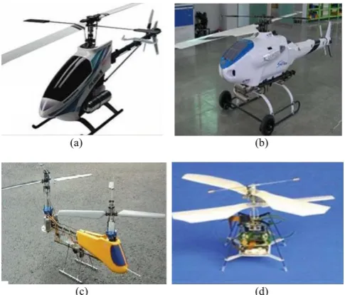
Many different rotor configurations for the single-mode in the model and vehicle size are shown in Fig. 1. The most classical, anti-torque design is an auxiliary rotor mounted vertically on the tail of the vehicle. Especially for conventional and Tandem helicopter as shown in Fig. 1(a), (b) and (c), the tail should be long so that a small tail rotor can generate a torque large enough to counter the main rotor torque. While the coaxial rotor configuration (d) consists of a pair of rotors mounted in a mast one above the other, and turning in opposite directions about the same axis of rotation. Compared to conventional helicopters, coaxial rotor configurations are normally more compact, stability, and thus less sensitive to wind gusts. Furthermore, in this paper decide to adopt the coaxial configuration for its compactness and stability.
The ground-based vehicles as shown in Fig. 2, there exist various designs such as the development mobile robot “All Terrain Robot Vehicles” (ATRV) for fire fighter services and dedicated to the risky intervention tasks. The other mode is a mobile Detection Assessment Response System (MDARS) program is executed by PM-FPS out of Fort Belvoir, VA. Space and Naval Warfare Systems Centre (SSC) Pacific have been involved in MDARS since the late
(a) (b)
(c) (d)
Fig. 1 Single-mode UAVs on the air operation. (a) Conventional main and tail rotor, (b) X - Copter1 by Skytech's, (c) Tandem and (d) FR by Chiba University and Epson
(a) (b)
Fig. 2. Single-mode UGVs on the ground locomotion (a) ATRV, (b) MDARS
1980’s as both the developer of the command and control system (the Multiple Resource Host Architecture or MRHA) and as the Chief Engineer for technical development and integration [6].
For the single-mode USVs, the US Navy did not release its first USV Master Plan until 2007, where a USV is defined as a vehicle which displaces water at rest and operates with near continuous contact with the water surface, capable of unmanned operations with varying degrees of autonomy. For example, as shown in Fig. 3(a), the Shipboard Deployed Surface Target (SDST) or X-Class renamed later “Roboski” with jet-ski chassis initially used as target drone then used as the reconnaissance vehicle test-bed.
(a) (b)
In [7] discusses, the basic motion estimation, guidance and control system of the Charlie prototype USV, an autonomous catamaran prototype equipped with a navigation package constituted only by GPS and compass as shown in Fig. 3(b). In this context, the design and implementation of an accurate and reliable navigation, guidance and control system, able to operate with only linear and angular position measurements, is fundamental to the development of relatively cheap remotely controlled vehicles for civil applications.
B. Dual-mode Vehicle
More generally, there are a number of small-scale vehicles and robots capable of multiple modes of locomotion in different environments; these largely consist of an unmanned air ground vehicle Fig. 4. [4], [8], design for a dual-mode air/ground personal vehicle [9], amphibious vehicle Fig. 5. [5], [10].
1) Air-ground Vehicle:
The vision of the U.S. Advanced Systems Directorate or Aviation and Missile Command (AMCOM) is merging technologies to develop one vehicle that incorporates both air and ground capabilities that will be the dominant reconnoitring unit on the future battlefield. Since the specification does not require that the vehicle actually move on the ground, wheels, legs, tracks, and other methods of ground mobility can be dropped from consideration. A simple solution is to utilize a system that is similar to most retractable landing gear systems used today. A landing strut will be housed within the skin of the vehicle and a push-pull pneumatic cylinder used to extend and retract the strut.
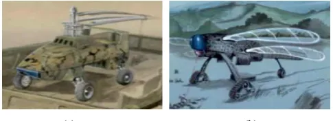
Some example, the “Pawnee”, illustrates in Fig. 4 (a) was chosen as a baseline concept design for air-ground vehicle based on a typical rotorcraft configuration. In [8] states, the vehicle had some limitation i.e. difficulty meeting the requirements of near-quiet acoustic signature and could not meet the requirements for autonomous operation.
Different with the “Oiseau”, a French word meaning bird, is a UAGV capable of meeting the future needs of US military forces. Utilizing an efficient design and mating together both technology and simplicity, the Oiseau meets the need of providing direct intelligence support during dirty, dangerous, and dull missions.
(a) (b)
Fig. 4. An unmanned-based air ground vehicle. (a) The Pawnee, (b) The Oiseau
The other example included the morphing micro air-land vehicle (MMALV) [11], which utilizes flexible-wing flight and wheel-legs, and the Entomopter [12], which uses flapping wing flight and legs. They are primarily UAVs and UGVs, with the ability to traveling once they land and water,
primarily as an aerial vehicle with a flight, landing, and traversing on the water surface mode for intermittent use.
Fig. 5. Unmanned autonomous amphibious vehicle
2) Ground-water Vehicle (Amphibious):
The design of the amphibious vehicle has been significant interest in the development of a vehicle that capable of amphibious operation. Such potential operations of an unmanned vehicle for a variety of reasons traversing to such places includes: terrain mapping, collecting and analysing water samples in possible contaminated environments, search and rescue, delivering items or tools from one location to another, security surveillance, and filming animals in their natural environments.
The computer-aided design (CAD) model of the autonomous amphibious vehicle (AAV) is shown in Fig. 5 (a). As shown, the AAV consists of a two segment body connected by a unique two degree-of-freedom joint. This two degree-of-freedom joint allows the two segments to pitch as well as roll with respect to one another while travelling. Four paddle wheels propel the AAV across the land and over water. Buoyancy attachments increase the buoyancy of the vehicle and are modular, which means they can be used as needed. Ultrasonic sensors are located in front, and they ensure the AAV can detect any obstacles along the way [5].
The other technology serving as an outdoor demonstrator for the research programme is the ARGO, an autonomous amphibious vehicle shown in Fig. 5(b). According to [10], the modelling of an autonomous amphibious vehicle and was developed at the Australian Centre for Field Robotics, Sydney. All parts of the vehicle’s driveline from the engine, continuously variable transmission (CVT), gearbox to wheels are analysed and modelled.
3) Air-water Vehicle:
In the air-water mode, national aeronautics and space administration (NASA) have conducted experiments with a seaplane by [13], intended for use as a small, unmanned, amphibious cargo carrier. The aircraft named as an autonomous cargo amphibious transport (ACAT) is intended to be a large cargo carrying unmanned aircraft that operates from water to avoid airspace and airfield conflict issues between manned and unmanned aircraft. The vehicle operated successfully but only in very calm conditions.
C. Three-mode Vehicle Description
three operation mode in this paper named as “three-mode vehicle”. Vehicle with one operation mode limited in their locomotion capabilities.
The three-mode vehicle features structure built in four main components, namely (1) a coaxial rotor set, (2) the propeller is attached at behind of the fuselage, (3) wheels, and (4) pontoon. All the mechanisms allow work independently of one another when fly on-air, move on-land, and capable of traversing across surface of the water.
As the presentation of the unmanned vehicle in existing technology survey follows, a direct comparison between vehicles and the proposed one is of need, in order to point out performance capabilities and design requirements finally used for this vehicle design. The tasks’ sequence in designing the vehicle consists of parameter’s design, determination of specification and configuration, weight estimation and distribution, initial sketch, conceptual design, final drawing and will end up with a component integrated. In this paper, the description for some of the sequence tasks will be accumulated in next section.
III. DESIGN,CONTROL AND TESTING METHOD A. Design Requirements
Before any design and construct a three-mode vehicle, the functional and performance requirements should be identified. The specific opportunities in designing process, as well as assumptions and constraints must be included as well. The challenge of this project is to create a small-scale vehicle that met the needs of the civil and military applications so that it can be perform a variety of operation modes. To support of multi function, the small-scale air-land-water vehicle will be supplied with a coaxial rotor, propeller, landing gear, pontoon and remote control system.
In this case, the following requirements consist of: The vehicle must be capable of vertical short take-off and
landing (VSTOL) from the land and/or surface of water. The vehicle has the capability of manoeuvring air,
on-land, and on-surface of water.
The vehicle must be capable of floating on the surface of water with a certain time.
The vehicle must be adaptable, upgradeable, and reliable for a variety of equipments that will be attached in the future for surveillance and monitoring purposes.
The vehicle should be simple to operate.
The vehicle should be easy to manufacture, assemble, and maintain.
B. Performance Requirements
The main difficulty in achieving a good performance for this vehicle with a coaxial rotor like common rotary-wing comes from the large hover on power requirements. Capability’s evaluation is done in terms of weight capability during hovering, maximum speed, ceiling and endurance; most critical parameters affecting such capabilities are available power, maximum weight, rotor design and special aerodynamic factors [14], [15].
In this design, the vehicle must be able to carry a small payload up to 20 grams when manoeuvre in the air, land and water mode. Typical operations of the vehicle are between 10−15 minute in the field under normal operating conditions.
The vehicle must be capable of vertical short take-off and landing (VSTOL) from the land and/or surface of water as well as movement rapidly from one location to the next. This
TABLEI
DESIGN SPECIFICATION OF A THREE-MODE VEHICLE
Parameter Specifications
Full length of vehicle 250 mm
Height full 280 mm
Width 205 mm
Main rotor diameter 460 mm
Propeller diameter 85 mm
Power system 2 x 370 carbon brushed motor
Propeller motor PPN 13 PB 12 C
Total weight 557 gram
Operation time ~ 10 min
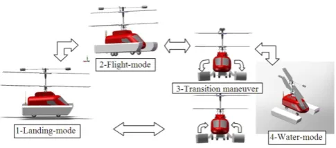
was interpreted as the ability of the vehicle to transition between flight, landing and water operation mode.
C. Vehicle Specification
The specification of the design proposed held on Table 1. These values also correspond to the Lama coaxial RC helicopter model E 020, 2.4 GHz, regarding range, weight, and speed. Base on this small helicopter, it’s developed and modified by attached a set propellers, suspension, steering control, and pontoons. Modifications required for operating the vehicle included:
Addition of a propeller system to power auxiliary equipment for vehicle operation on the surface of the water.
Addition of pontoon for floating and traversing capability on the water surface.
Integration of actuators for pontoon and steering control. In this paper, micro servo actuators were selected due to ease of integration and light of weight.
Addition of tire and tower pro servo for vehicle movement when operated on land.
This research decided to adopt a coaxial configuration, mainly for its VTOL, compactness and stability. The basic idea was to develop the vehicle passively stable in roll and pitch while preserving good manoeuvrability in 3D translations.
D. Parameters Design
Design parameters were selected after a detailed literature survey studying the characteristics of existing small-scale unmanned vehicles. While designing, it is assumed that the designed vehicle will be considered with the specification as shown in Table 1. For the perfection of a vehicle design, it would require in-depth studies in the following areas:
Structures design: frame, landing gear and pontoon mechanism.
Power system: battery, brushed motor, motor-mini and transmission.
Control mechanism: swashplate, control linkages, servo actuators and stabilizer linkages.
Working on all construction models of the vehicle was mainly based on two-dimensional computer-aided-design (2D CAD) and powerful three-dimension design assembly environment. Three-dimensional design software SolidWorksTM and CosmosWorksTM are used throughout the
design and manufacturing stage for faster and efficient prototyping. The components needed in the system were also derived by using these computer tools. Fig. 6 represents that the overall simplified CAD structural and detail main components of the vehicle, while Fig. 7 represents the four views of the vehicle.
E. Centre of Gravity
The position of the centre of gravity mainly is crucial for flying. The type of propulsion used is an important factor of defining the best C.G. position. In the proposed design, it positioned for the centre of gravity on a single-rotor like a helicopter is slightly ahead of the main rotor shaft, exactly on the axis of rotation of the main rotor [16]. In this way, the frame remains horizontal during hovering; controlling and manoeuvring the vehicle becomes easier.
The advantage of SolidWorksTM and CosmosWorksTM is
the centre of gravity for a design can be shown straight forward in the drawing. However, all the drawing and design must be done with actual scale. SolidWorksTM and
CosmosWorksTM with build-in main components and
carefully defining the mass properties of the structure, the total weight and centre of gravity (C.G) location are obtained, as shown in Fig. 8.
Fig. 6. A simplified CAD structural and main component of the vehicle
Fig. 7. Four views of the vehicle.
Fig. 8. Defining C.G location using SolidWorksTMand CosmosWorksTM
F. Control System
A fundamental operation control system includes radio control electronics and batteries. This vehicle has a multifunction control system, known as 4 in 1 mixing controller. The basic diagram of the component connection is shown in Fig. 9.
The radio control electronics consisted of an RF receiver, six servos, a signal mixer with gyro system and speed controller. The micro-sized receiver has a mass 15 g, and acquires the radio signal from the controller (ESKY Transmitter 001725). Two servos weigh 7.5 g acquires the signal from receiver channel 1, to drive independently the aileron and rudder. Rudder is used to change the direction of the vehicle when operated on land and in water. Channel 2 on the receiver, to drive the servo weighs 7.5 g. It’s used for the movement of the elevator and tower-pro servo controller forward-backward vehicle when operated on the land.
The signal mixer plus gyro system has weights 10 g. It commands used to generate adequate signals for servos that perform the functions of both elevators and ailerons. This signal was controlled by channel 3 and 4.
TABLEIII
COMPONENTS AND ELECTRONICS OF THE VEHICL
Item Qty Specifications Weight (g)
Receiver 1 FKS-6 channel 13.0
Battery 1 Li-polymer 11.1 V
800 mAh
65.0
4 in 1 controller 1 Esky mixed control 10.0
Main motor 2 370 w/12T 84.0
Motor-mini 1 PPN13PB12C 17.0
Servo (@ 7.5 g) 4 Speed 0.1 s/60° 30.0
Servo (@ 9 g) 2 Speed 0.15 s/60° 18.0
Tower pro 1 Speed 0.24 s/60° 55.2
Pontoon 2 Stereo foam 22.0
Propeller 1 Plastic material Ø 85
mm
9.0
Vehicle main frame
& Other parts Structure 233.8
Total 557
Channel 3 is a controller signal that can be adjusted from the function of the throttle into the controller function of the propeller. While channel 5 has a function as a controller servo weigh 7.5 g, and used to control the operation of media (i.e. air, land and water). Two servos weighs 9 g are used to drive sets of foldable pontoons. Operation is controlled by the channel 6.
The radio control electronics used herein were the smallest and lightest that could be obtained within the budget and availability in the market. In particular, the addition electronic and assembling were selected as well as possible not exceed to the weight constraint. The vehicle component, electronics and its mass distribution are shown in Table 2 and Fig. 10 respectively.
The best source of energy using currently available technology is the Li-polymer battery [17]. An 11.1V Extreme Li-polymer battery pack with a 20oC discharging
current is used for this vehicle. A capacity of 850 mAh is favoured given the weight consideration and maximum current limit. The position of placement some electronic component is shown in Fig. 11.
Fig. 10. Vehicle mass distribution
Fig. 11. Placement of electronic components
Fig. 12. Vehicle operation and layout considerations
G. Testing Consideration
The concept’s layouts were weighed and combined to create a composite design. Vehicle design test layout was selected based on experience and general micro and small-scale vehicle knowledge. These parameters are used as a basis for selecting vehicle configurations. Parameters such as amperage configuration, rotary wing design, landing gear and pontoon are to be considered in conceptual design phase. The basic small-scale vehicle shape and operational concept can be seen in Fig. 12.
As the assumption during vehicle testing, there is no extreme environment, such as hurricanes, blizzards, and waters with the strong wave. The operator controls the vehicle in the field through the use of a remote control.
IV. VEHICLE TESTING
A series of testing was conducted to assess the performance of the unmanned-base vehicle designs. Vehicle trajectory can be done starting from the ground into the air until finally descend on the water. Or instead take off from the surface of the water and then flew until also landed on the ground. The vehicle is piloted with the ET 6I transmitter R/C controller, which has six programmable channels for signal mixing and processing.
A. Combination Function
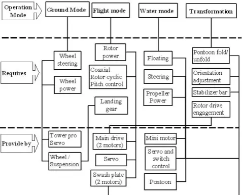
for several different functions. As illustrated in Fig. 13, each mechanism on the vehicle serves several functions, each of which is necessary for at least one of the vehicle’s primary actions. To handle all the necessary functions in the overall mode of operation, then the transformation mechanism should work fine and perfect. The application for multi-purpose components in miniature air vehicles and particularly in hybrid-locomotion designs have been noted before [12]. This work not only helps reduce weight, but also requires a number of interactions between mechanisms, in effect, increasing system complexity. Reducing this complexity will be one of the primary aims for future development.
Fig. 13. A diagram illustrating the role of each mechanism in the function of the vehicle
B. Flight Test
To demonstrate the feasibility of the prototype operation, real flight tests were successfully carried out. For the first flight tests of the vehicle were conducted without a payload to establish the feasibility of the developed vehicle. Fig. 14 illustrates the vehicle in the flight test.
The vehicle had been well trimmed, the turning, climbing and descending abilities were all tested. The vehicle was launched by vertical take-off with main rotor speed range 5000 – 5600 rpm, and flight altitude ware around 2 m. The electrically powered vehicle produced very little noise during the flight test and was barely heard by people on the ground 20 m away.
Fig. 14. The vehicle manoeuvre during flight test
C. Landing Test
The surface testing of the prototype ware conducted in the fine land environment as the operating speeds are only up to 0.11 m/s. Fig. 15 are the illustration of the vehicle demonstrations on the land.
Fig. 15. Demonstration test during on the land movement.
D. Water Surface Test
The surface testing of the prototype ware conducted on shallow water and has velocity of 0.47 m/s. Fig. 16 are the illustration of the vehicle demonstrations since on water traversing.
Fig. 16. Demonstration test on the water surface
E. Performance Analysis
The comparison of the maximum forward speed was determined from the experiment as shown in Fig. 17.
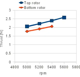
Fig. 18 shows the experiment variation of mean thrust with rpm for individual rotors as well as the entire system. Top rotor thrust is under-predicted by approximately < 2% at all speeds, whereas the bottom rotor thrust is over-predicted about < 8% [18].
Fig. 18. Thrust (mean) versus rpm
Since the vehicle traveling on the water at a constant speed, the thrust produced by the motors and propeller are equal to the friction or drag of the vehicle. It can be calculated by using equation 1, that is
ℎ = = 0.5 (1)
ℎ = = 0.5 1.225 0.000085 0.47
ℎ = = 0.000012 .
where is the air density 1.225 kg/m3, V is the vehicle speed
0.47 m/s, A is the propeller effective surface area, 85 mm2.
Power consumption equation 2 for the propulsion system increases dramatically as the speed of the vehicle increases. This is because the thrust power (Watt) is equal to the product of the thrust and the speed, meaning thrust power is a function of speed cubed,
ℎ = ℎ × (2)
ℎ = 0.000012 × 0.47
ℎ = 0.00000564 .
Therefore, because of the vehicle’s limited energy supply, it must travel at a speed that does not draw too much power, but at the same time does not take too long to complete its mission. Performance parameters that can be improved are, among others, maximum speed, power consumption, maneuverability, payload, range, endurance, stability and so on. Improving some or all of these parameters would increase efficiency of flight, landing, and traversing, thus widening the possible mission profiles that the vehicle can perform.
V. CONCLUSIONS
This paper has presents the first design and testing of an unmanned three-mode vehicle. The prototype design consists of four main components, whereby a coaxial rotor set, propeller attached at the behind of fuselage, wheels/suspension, and pontoon mechanism. The design sequences followed by testing, which include the structural design and components integration, performance analysis had been done successfully. Flight and surface tests have been shown that validate and availability the overall design. The propulsion system was narrowed down to a double 370 motor w/12T, coaxial rotor, and supported by a single propeller system with flexible vectoring and direct drive. The propeller was used for water traverse chosen to be composite and two bladed. The construction of the vehicle
can be used as an excellent platform for future research and development mainly in the unmanned system field. This vehicle is an ideal investment for those people looking to move onto the larger scale. It also can be used for testing and learning conventional and advanced control algorithms and techniques to other small vehicle systems. With a limited budget, a small-scale vehicle has been built up using a simple design and tool. The future plan of the development will be applied autonomous controller so that the developed vehicle becoming more intelligent and moving itself.
ACKNOWLEDGMENT
This research was supported by Universiti Tun Hussein Onn Malaysia. The authors also would like to thank Mr. Prima Adhi Yudistira for his contributions to this project.
REFERENCES
[1] R. Bloss, “By air, land and sea, the unmanned vehicles are coming,” Emerald group, vol. 34/1, pp. 12–16, 2007.
[2] P. Spanoudakis, N. Tsourveloudis, and K. Valavanis, “Design considerations of a prototype vtol robotic vehicle through market survey data collection,” Journal intelligent robot system, Springer Science+Business Media B.V, pp. 339–364, 2006.
[3] K. Muljowidodo, S. A. Nugroho, N. Prayogo, and A. Budiyono, “Design and testing of underwater thruster for Shrimp ROV–ITB,” Indian Journal of Marine Sciences, vol. 38(3), pp. 338–345, 2009. [4] A. Kossett, R. D’Sa, J. Purvey, and N. Papanikolopoulos, “Design of
an improved land/air miniature robot,” in International Conference on Robotics and Automation. IEEE, May 3-8, 2010 2010, pp. 632– 637.
[5] F. Michael and S. Nokleby, “Design of a small-scale autonomous amphibious vehicle,” in Proceeding of CCECE/CCGEI, Florida, 2008, pp. 000781–000786.
[6] B. Shoop, M. Johnston, R. Goehring, J. Moneyhun, and B. Skibba,“Mobile detection assessment and response system (mdars): a force protection, physical security operational success,” in Unmanned Systems Technology VIII, Defense & Security Symposium, Orlando, Florida, 2006.
[7] M. Caccia, M. Bibuli, R. Bono, and G. Bruzzone, “Basic navigation, guidance and control of an unmanned surface vehicle,” Autonomous Robot, Springer Science+Business Media, vol. 25, pp. 349–365, 2008.
[8] M. Janetka, L. Filz, N. Smith, and J. R.A. Frederick, “Unmanned air ground vehicle,” in Joint Propulsion Conference and Exhibit, American Institute of Aeronautics and Astronautics, 2001, pp. 1–14. [9] I. James F. Marchman, N. Intaratep, and W. H. Mason, “A design for
a dual-mode personal vehicle,” American Institute of Aeronautics and Astronautics, AIAA, vol. 5877, pp. 1–9, 2002.
[10] T. Tran, Q. Ha, R. Grover, and S. Scheding, “Modeling of autonomous amphibious vehicle,” Australian Centre for Field Robotics (ACFR), pp.1–7, 2004.
[11] F. Boria, R. Bachmann, P. Ifju, R. Quinn, R. Vaidyanathan, C. Perry, and J. Wagener, “A sensor platform capable of aerial and terrestrial locomotion,” Intelligent Robots and Systems (IROS), 2005. [12] R. C. Michelson and S. Reece, “Update on flaffing wing micro air
vehicle research-ongoing work to develop a flapping wing, crawling "entomopter",” in 13th Bristol International RPV Conference, 1998.
[13] G. Pisanich and S. Morris, “Fielding an amphibious UAV: Development, results, and lessons learned,” in The 21st Digital
Avionics System Conference, 2002.
[14] J. Seddon, Basic Helicopter Aerodynamics. Oxford: BSP Professional Books, 1990.
[15] J. G. Leishman, Principles of Helicopter Aerodynamics, 2nd ed. Cambridge University Press, 2005.
[16] R. Prouty, Helicopter Performance Stability, and Control. Krieger, Florida, 1990.
[17] J. Grasmeyer and M. Keennon, “Development of the black widow micro air vehicle,” AIAA-0127, 2001.