*Corresponding author: Ashish Gupta ISSN: 0976-3031
Research Article
COMPARATIVE ANALYSIS OF CONTROLLERS DESIGNED FOR A LOAD
FREQUENCY CONTROL
Ashish Gupta
1, Yashi Gupta
2, Akash Deep Gupta
2and Maurya K. K
21
Department of Electrical Engineering Graphic Era University, Dehradun, Uttarakhand, India
2MCAET, Akbarpur, Ambedkarnagar, Uttar Pradesh, India
DOI: http://dx.doi.org/10.24327/ijrsr.2019.1003.3244
ARTICLE INFO ABSTRACT
This study presents the analysis of control techniques of PID tuning parameters for load frequency control (LFC) of power system in order to maintain the frequency regulation. There are five tuning techniques is used to cognize the problem of load frequency control such as Ziegler-Nichols (ZN), Honeywell Tuning, Internal Model Control (IMC) based PID Controller Direct Synthesis (DS) and IMC based PID controller with first order filter. The primary attention of this paper is to collate these tuning techniques for single input and single output (SISO) system using MATLAB SIMULINK and using the model order reduction techniques with the help of ROUTH approximation, SKOGESTAD method and TAYLOR approximation method. third order system’s LFC abolished into second order model, second order plus dead time (SOPDT) model and first order plus dead time (FOPDT) model by using this three MOR techniques. This paper identified the comparative dissection of execution diagnosis of isolated response entire in the indication of time and frequency response specification. It is accomplished that Inter Model Control based PID Controller with first order filter demonstrate the better performance comparatively.
[
INTRODUCTION
Load frequency control (LFC) has a basic control structure or arrangement, of parts of the machine and similar devices in term of power system operation and control. Load frequency control use to keep the uniform frequency during changing load. When system frequency is changed, the main problem is that the system output of generating units cannot be controlled with in specified limit is called Load frequency control (LFC) [1]. Reasonable to extensive power, insolubility is extended of contemporaneous power system, sublimated and predicted control prescripts are proficient in load frequency control; e.g. conventional control [2-3]; variable structure control [4]; self-tuning control [5] intelligent control [6]; optimal control [7-8]; adaptive control [9]; robust control [10-11]; and advanced fuzzy and ANN controller [12-14] etc. Improved performance is expected from the advanced control method [15] required to get knowledge on the system or to identify an online recognizer parameters. It does not apply in practical PID controller for load frequency control study due to their simplicity. Power system with various commercial and industrial loads and rotating mass with the help of turbines, Governors and Generator with loads required to perform at a uniform and
invariable frequency. So Load frequency control is an extremely significant and specific crux in Power system operation, process, influence and control with good quality, to provide sufficient, easy, a dependable and accuracy electrical power. When demand is increased due to manufacturing, the electrical power is becoming complex and complicate. For satisfactory networks operation the frequency controlled and remains nearly uniform. As the load varies at single, double and multi areas with Power system, the frequency relates to work multi areas affect through Tie lines. A premeditating and changing frequency transients and load execution appliance disservice instruments, when the transmission lines are overloading and overcharge, networks fully antagonized to preserve the equipments, so that tuning controllers are designed to protect the system’s equipments. This is an unsteady and instability circumstances for the electric Power system. Controllers are designed to control the unstable condition and maintain the frequency. The primary point is that, when the Load frequency controller is deflected unsettled circumstances of the system, Power system will be stable. All conditions and equipment (loads, governor and turbine) of the Power system is digested [16]. It is a main role to fulfill the application of Power system, When the active power and reactive power is
Available Online at http://www.recentscientific.com
International Journal of
Recent Scientific
Research
International Journal of Recent Scientific Research
Vol. 10, Issue, 03(C), pp. 31357-31363, March, 2019
Copyright © Ashish Gupta et al, 2019, this is an open-access article distributed under the terms of the Creative Commons Attribution License, which permits unrestricted use, distribution and reproduction in any medium, provided the original work is properly cited.
DOI: 10.24327/IJRSR CODEN: IJRSFP (USA)
Article History:
Received 06th December, 2018 Received in revised form 14th January, 2019
Accepted 23rd February, 2019 Published online 28th March, 2019
Key Words:
controlled it and controller are use to control equipment for safety purpose, because active power is directly proportional to system frequency in the Power system. Frequency is a main part in any system , for e.g. if the average frequency of single mechanism is 50 Hertz, and the mechanism frequency curtain falls underneath 48.5 Hertz, and itinerate to elevated level 51.5 Hertz so in this condition the blades of the turbine are damaged and all equipments of the Power system like generators, governors will be damaged. It is very difficult to control the whole part of the Power systems and active power can be reflected, so that Power system’s equipments may be harmful [17]. Most of the controllers are designed to control the load and frequency in Power system by researchers over the past decades [18-19]. The basic object of load frequency control is to adjust the output power of the Power system like generator turbine and load at prescribe level when the frequency is fluctuated. So many tuning prescripts are consumed in the power system via Internal Model Control (IMC) based PID controller [20-23] and Internal Model Control (IMC) based PID controller with first order filter [24-26] has been manifested. The flow of active and passive power in the transmission and distribution lines are independent to each other and this paper follow to control design for load frequency control and the controller can be improved the transient part of the Power system and system’s stability improve [27].
This paper PID controller design for third order system using Ziegler-Nichols technique [28-29] (closed loop method), and performing parameter can be observed. The Ziegler-Nichols technique is a most popular technique in the PID tuning techniques. It is suitable only when system input is step. The main drawback of Ziegler-Nichols method show higher percentage overshoot. So Honeywell [30-31] technique preferred to minimize the overshoot of the system but Honeywell technique consist second order process [32]. The Ziegler-Nichols and Honeywell are designed controller parameters with tuning to show satisfactory performance and results. In this Direct Synthesis (DS) impenitence [33-34], the composition is founded on a cherished closed loop transfer function for an exclusive second-order-plus-dead-time (SOPDT) system. From such a Direct Synthesis (DS) controller, PID controller designed with varied prescript [35]. Generally Internal Model Control (IMC) based PID controller with first order filter is a promoted technology to optimize higher order system to low order system and system is deficient sophisticated and all parameters (percentage overshoot, settling time, rise time and steady state error) of the system is less than Ziegler-Nichols, Honeywell tuned controller, Direct Synthesis (DS) controller and Internal Model Control based PID Control without changing parameters of FOPDT, SOPDT and third order process. Many advanced control strategies improve and implement in load frequency control and automatic generation control of single area Power system, double and multi area Power system [36-40].
The convenience of the paper is convener as ensues: The transfer function model of Non-Reheated Turbine Power system with no Droop characteristic associate in Section 2, A PID controllers has being designed for a first, second and third order system with transfer function in Section 3, section 4 consist of the Different types of technique use to design a PID controller, Simulation consequence and contention section exhibit 5 and section 6 demonstrate the conclusion of the topic.
Lfc- PID Design
LFC Design Non-Reheated Turbine
The non-reheated turbine of the load frequency control (without droop characteristics) formation of three parts as shown in Fig.1:
Governor with Dynamics
s
s
G
a a
1
1
)
(
(1)Turbine with Dynamics
s
s
G
c c
1
1
)
(
(2)Load and Machine with Dynamics
s
K
s
G
l l l
1
)
(
(3)The open loop transfer function of load frequency control (LFC) is:
)
(
)
(
)
(
)
(
s
G
s
G
s
G
s
P
a c l (4))
1
)(
1
)(
1
(
)
(
s
s
s
K
s
P
l c
a l
(5)Governor Turbine Load & Machine
Droop Characteristics
_ Pg
Pt Pl Fo
Pd
U
Fig. 1. Block diagram of a single area Power system with droop characteristics
Generalised Model of PID Controller
PID controller employed in the process control industry. The main reason is that by the control system engineers due to their flexibility and reliability and robust of the system PID controller is widely used. Fig 2 shows block diagram of PID controller with Load Frequency control with single area power system with droop characteristics. Where Gg, Gt and Gl indicate
governor, turbine and load and machine transfer function. A PID controller represented in transfer function forms as:
s
K
s
K
K
s
K
i dp
)
(
(6)Where,
p
i
K
Integral gain
d
K
Derivative gainGg Gt Gl
_
+ Pg Pt Pl
Pd
PID Controller
1/R
Fig 2 Block diagram of PID Controller with LFC
Design Consideration
PID controller is designed for a first, second and third order system with transfer function.
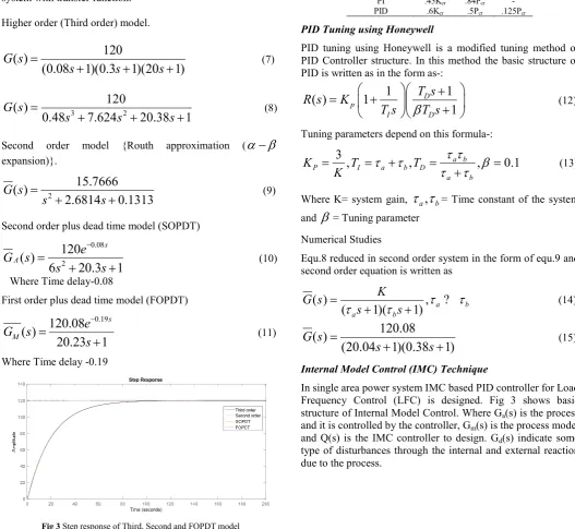
Higher order (Third order) model.
120
( )
(0.08
1)(0.3
1)(20
1)
G s
s
s
s
(7)3 2
120
( )
0.48
7.624
20.38
1
G s
s
s
s
(8)Second order model {Routh approximation (
expansion)}.
2
15.7666
( )
2.6814
0.1313
G s
s
s
(9)Second order plus dead time model (SOPDT)
0.08
2
120
( )
6
20.3
1
s
A
e
G
s
s
s
(10) Where Time delay-0.08First order plus dead time model (FOPDT)
0.19
120.08
( )
20.23
1
s
M
e
G
s
s
(11) Where Time delay -0.19Fig 3 Step response of Third, Second and FOPDT model
Design of PID Controller for Different Tuning Method
Ziegler-Nichols Method
We design a PID controller using second method (closed loop).It is known as online tuning method or ultimate gain. The first method of Ziegler-Nichols is called process reaction curve but it is used to open loop system. When Ziegler Nichols tuning techniques is closed loop process. By Integral gain(Ki) = 0 and
Derivative gain (Kd) = 0 and it use Proportional controller (Kp)
only i.e. (Kp not equal to zero).The value of gain (Kp) increase
so that response will be damping oscillation. Table l show Ziegler-Nichols based PID controller, where Kcr show ultimate
gain and Pcr ultimate period
Table 1 zeigler-Nichols Method
Type of
controller
K
p
i
dP .5Kcr - -
PI .45Kcr .84Pcr -
PID .6Kcr .5Pcr .125Pcr
PID Tuning using Honeywell
PID tuning using Honeywell is a modified tuning method of PID Controller structure. In this method the basic structure of PID is written as in the form as-:
1
1
( )
1
1
D pI D
T s
R s
K
T s
T s
(12)
Tuning parameters depend on this formula-:
3
,
,
a b,
0.1
P I a b D
a b
K
T
T
K
(13)Where K= system gain,
a,
b= Time constant of the system and
= Tuning parameterNumerical Studies
Equ.8 reduced in second order system in the form of equ.9 and second order equation is written as
( )
,
(
a1)(
b1)
a bK
G s
s
s
?
(14)120.08
( )
(20.04
1)(0.38
1)
G s
s
s
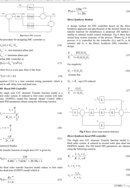
(15)Internal Model Control (IMC) Technique
In single area power system IMC based PID controller for Load Frequency Control (LFC) is designed. Fig 3 shows basic structure of Internal Model Control. Where Ga(s) is the process
and it is controlled by the controller, Gm(s) is the process model
and Q(s) is the IMC controller to design. Gd(s) indicate some
Q(s) Ga(s)
Gm(s)
Gd(s)
D(s) + Y(s) E(s) R(s) + U(s)+
-Fig 4 Basic IMC structure
The procedure for designing IMC controller is
m mm
s
G
G
G
(
)
(16)
m
G
non minimum phase part
m
G
minimum phase part Define IMC controller as)
(
)
(
)
(
s
G
1s
F
s
Q
m (17)Where F(s) is a low pass filter of the form
)
1
(
)
(
s
s
F
(18)Equation (12)
is a time constant tuning parameter which is used to add delay time and dead time.IMC Based PID Controller
The single area LFC structure Transfer function model is a third order system. It reduced to first order system with time delay (FOPDT) model.The Internal Model Control (IMC) based PID parameters obtain using the following reaction.
)
2
(
2
c g t PK
K
(19)2
I
t
(20)
t t D2
(21)Numerical Studies
The transfer function of single area LFC is given by
1
38
.
20
624
.
7
48
.
0
120
)
(
3 2
s
s
s
s
P
(22)The third order transfer function model reduce to first order plus dead time (FOPDT) model which is
s
Ke
s
P
s
1
)
(
(23)s
e
s
P
s20
1
120
)
(
38 . 0
(24)Direct Synthesis Method
A design method for PID controller based on the Direct Synthesis approach and specification of the desired closed loop transfer function for disturbances is proposed. DS method is similar to internal model control technique. Fig 4 show basic closed loop system structure of the process. Where Gp is the
process, it is controlled by the controller (Gc) and Gv is the
actuator and Gc is the Direct Synthesis (DS) controller to
design. f p v c p v c
i
G
G
G
G
G
G
KG
Y
Y
1
(25)For simplicity
f p v
a
G
G
G
G
(26)Assume that
K
G
f
, equ.(19) reduceda c
a c
i
G
G
G
G
Y
Y
1
(27)K
G
cG
dG
PG
VG
fYi Ya
+ _
E P U Yo Y
Yd
D
Xf
Fig 5 Basic close loop system structure
Direct Synthesis based PID controller
The single area LFC structure Transfer function model is a third order system. It reduced to second order plus dead time (SOPDT) model. The DS based PID parameters are obtained using the following reaction.
c b a cK
K
1
(28)b a
I
(29) b a b a D
Numerical Studies
The transfer function of single area LFC is given by
)
08
.
0
1
)(
3
.
0
1
)(
20
1
(
120
)
(
s
s
s
s
T
(32)The higher order transfer function model is reduced to second order plus dead time (SOPDT) model which is
)
1
)(
1
(
)
(
2
1
s
s
Ke
s
P
s
(33)
s
s
e
s
P
s
3
.
0
1
)
20
1
(
120
)
(
08 . 0
(34)
Internal Model Control based PID Controller with first order filter
In the Internal model control based PID controller design, the filter selection is most important role. So IMC suggest nth order filter but nth order filter is a higher order filter and system is heavy complex, cost and size of the controller increased so nth order filter reduce into second and first order filter but first order filter easy to formulation of the IMC based PID controller structure. System is easy to manage different tasks. It is written as-
( )
(1
)
nF s
s
(35) Where F(s) =low pass filter, n =number of order of filter IMC controller Q(s) design the selecting process of filter. Q(s) represent into controller C(s) of conventional unity feedback control system.1
( )
( )
( )
( )
1
( )
1
( ) ( )
M
M
F s G
s
Q s
C s
F s
G
s Q s
(36)Where
G
M show model structure and it is modified in the form of FOPDT/SOPDT system. For FOPDT system n(no of filter) is 1 and for SOPDT n is 2 and main drawback of second order filter is that to generate extra leg term including PID controller. So first order filter is proposed and no need of higher order filter for higher order plant and first order filter Control based PID controller.1
( )
( )
( ) ( )
( )
MM
F s
Q s
G
s F s
G
s
(37)The basic procedure for designing IMC controller filter
IMC Based PID Controller with First order filter
2
;
, , ,
0
M
K
G
K a b c
as
bs
c
?
(38)1
( )
;
1
(1
)
nF s
n
s
(39)2
( )
( )
(1
)
( )
MF s
as
bs c
Q s
K
s
G
s
(40)2
( )
( )
1
M( ) ( )
Q s
as
bs c
C s
K s
G
s Q s
41)Where
G
M( )
s
represent model of th system (second order process) and K, a, b, c is dependant variable and it is greater than always zero. C(s) is a controlled process and equ.38 and equ 39 compare it and determine the value of PID control parameters.( )
IP D
K
C s
K
K s
s
(42);
;
P I D
b
c
a
K
K
K
K
K
K
(43)RESULT
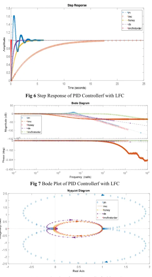
A Proportional-Integral-Derivative (PID) tuning method of Power system load frequency control suggest on a Ziegler-Nichols, Honeywell, Internal Model Control, Direct Synthesis method and IMC based first order filter. The simulation result shown in fig 6 and Table II. It confirms that the IMC based first order filter controller can be provided better performance compare to Ziegler-Nichols with PID controller, Honeywell and IMC based PID controller to analyze due to table II and figure.6. IMC based first order filter controller is a simple design approach. In this paper load frequency control was proposed order reduction technique to reduce the higher order to second order plus dead time (SOPDT) and first order plus dead time (FOPDT). The performance of the closed loop system has effectively improved with second order reduced system model instead of full order system with PID controller with different type of tuning techniques (Internal model control, Direct Synthesis).Parameter value for higher order and reduced order with IMC and Direct Synthesis has been compared and finally noticed that Rise time, Peak time, %overshoot, settling time etc are reduced effectively. Fig 7 compares the bode plot of the Ziegler-Nichols, Honeywell, IMC based PID Controller, Direct Synthesis and IMC based first order filter. It is clear that the IMC based first order filter controller provide best result in a wide frequency. Fig 6 shows simulation result for given process with PID tuning technique and IMC based first order filter provide better performance than Ziegler-Nichols, Honeywell, IMC based PID Controller due to no overshoot and less settling time.
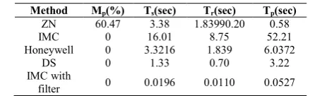
Tabel 2 Comparison of PID tuning techniques with time specification parameters
Method Mp(%) Ts(sec) Tr(sec) Tp(sec)
ZN 60.47 3.38 1.83990.20 0.58
IMC 0 16.01 8.75 52.21
Honeywell 0 3.3216 1.839 6.0372
DS 0 1.33 0.70 3.22
IMC with
Fig 6 Step Response of PID Controllerf with LFC
Fig 7 Bode Plot of PID Controllerf with LFC
Fig 8 Nyquist Plot of PID Controllerf with LFC
CONCLUSION
This paper covered an overview and this is summary of PID controller, design a PID controller using Ziegler-Nichols, Honeywell, Inter model control, Direct Synthesis technique and IMC based first order filter for first, second and third order process. Simulation results using MATLAB Simulink discuss for Z-N tuned PID controller, Honeywell, IMC based PID controller, Direct Synthesis technique and IMC based first order filter. Ziegler-Nichols technique gives higher overshoot with zero steady state error. IMC based PID controller gives zero steady state error and no overshoot and smaller settling time and IMC based first order filter controller gives no overshoot, zero steady state error and smaller settling time than obtain using Ziegler-Nichols, Honeywell, Direct Synthesis and IMC based PID controller.
References
1. P. Kundur, “Power system stability and control, ” New YorkP: McGraw Hill, 1994.
2. S. Sondhi and Y.V. Hote, “Fractional order PID Controller for load frequency control,” Energy convers. Manag., pp. 343-353, 2014.
3. M.N. Anwar and S. Pan, “A new PID load frequency control design method in frequency domain through Direct Synthesis approach,” Elec. Power & Energy syst., pp. 560-569, 2015
4. N.N. Bengiamin and W.C. Chan, “Variable structure control of electric power generation, ” IEEE Trans. Power App. Syst., pp. 2271-2285, 1972.
5. A. Demiroren, N.S. Sengor, and H.L. Zeynelgil, “Automatic generation control by using ANN technique,” Electrical Power component system, pp. 883-896, 2001.
6. M. Calovic, “Linear regulator design for a load and frequency theory,” IEEE Trans. Power App. Syst., pp. 2271-2285, 1972.
7. R.K. Cavin, M.C. Budge, and P. Rasmussen, “An optimal linear system approach to load frequency control,” IEEE Trans. Power App. Sys., pp. 2472-2482, 1971.
8. M. Azzam, “Robust automatic generation control, ” Energy convers. Manage., pp. 1413-1421, 1999.
9. C.T. Pan and C.M. Liaw, “An Adaptive controller for power system load frequency control,” IEEE Trans. Power syst., pp. 122-128, 1989.
10. M. Azzam, “Robust automatic generation control, ” Energy convers. Manage., pp. 1413-1421, 1999.
11. A. Khodabakhshian and N. Golbon, “Robust load frequency controller design for hydro power system, ” in proc. IEEE conf. control application (CCA), pp. 1510-1515, 2005.
12. G.A. Chown and R.C. Hartman, “Design and experience with a fuzzy logic controller for automatic generation control, ” IEEE Trans. Power Syst., pp. 965-970, 1998. 13. J. Talaq and F. Al-Basri, “Adaptive fuzzy gain
scheduling for load frequency control, ” IEEE Trans. Power Syst., pp. 145-150, 1999.
14. H. Shayeghi and H.A. Shayanfar, “Application of ANN technique based on µ- synthesis of load frequency control of interconnected power system, ” Electrical power energy syst., pp. 503-511, 2006
15. S. Baghya Shree and N. Kamaraj, “Hybrid neuro fuzzy approach for automatic generation control in restructured power system,” Electrical power energy syst., pp. 274-285, 2016.
16. S.K. Gautam and N. Goyal, “Improved partical swarm optimization based load frequency control in a single area power system,” IEEE, pp. 1-4, 2010.
17. H. Shayeghi and A. Jalili,“Load frequency control strategies: A state of the art survey for the researcher, ” Energy convers manage., pp. 344-353, 2009.
18. S. Sondhi and Y.V. Hote, “Fractional order PID controller for load frequency control, ” Energy conversion and manage., pp. 343-353, 2009.
approach for PID tuning,” Journal of Process Control, pp. 1220-1234, 2010.
20. S. Saxena and Y.V. Hote, “Simple approach to design PID controller via internal model control , ” Arab. J. Science Eng., pp. 3473-3489, 2016.
21. S. Saxena and Y.V. Hote, “Advances in internal model control technique: A review and future prospec ts, ” IETE Tech, pp.461-472, 2012.
22. S. Saxena and Y.V. Hote, “Load frequency control in power system via Internal model control scheme and Model order reduction, ” IEEE Trans., Power syst., pp. 2749-2757, 2013.
23. S. Saxena and Y.V. Hote, “Internal model control based PID tuning using first order filter,” International Journal of Control, Automation and Syst., pp. 149-159, 2017. 24. S.K. Gautam and N. Goyal, “Improved partical swarm
optimization based load frequency control in a single area power system, ” IEEE, pp.1-4, 2010.
25. S. S axena and Y.V. Hote,“Stabilization of perturbed system via IMC: An application to load frequency control, ” Control Engineering Pract,. pp. 61-73, 2017. 26. D.E. Rivera, M. Morari, and S. Skogestad, “Internal
model control: PID controller design,” Industrial and engineering chemistry process design and develop., pp. 252-265, 1986
27. R. C. Panda, C. C. Yu, and H. P. Huany, “PID tuning rules for SOPDT systems: Review and some new Results, ” ISA Transactions, PP. 283-295, 2004.
28. M. N. Anwar and S. Pan,“A new PID load frequency controller design method in frequency domain through direct synthesis approach,” Elec. Power and Ener. Syst., pp. 560-569, 2015.
29. K. Jagatheesan, B. Anand, and, M.A. Ebrahim., “Stochastic Partical Swarm Optimization for tuning of PID Controller in Load Frequency Control of Single Area Reheat Thermal Power System,” International Journal of Electrical and Power Engineerning, pp. 33-40, 2014.
30. K. Jagatheesan, B. Anand, and, Nilanjan Dey, “Automatic generation control of Thermal-Thermal Hydro Power System with PID Controller using ant colony optomization,” International Journal of Service Science, Management, Engineering, and Technology, pp. 18-34, 2015.
31. S. K. Pandey, S. R. Mohanty, and, N. A. Kishor, “literarture survey on load frequency control for conventional and distribution generation power system,” Renew Sustain Energy Rev, pp. 18-34, 2013.
32. Tan. W., “Tuning of PID load frequency controller for power system, Energy Convers. Manage., pp. 1465-1472, 2009.
33. Dan Chen and Dale E. Seborg, “PI/PID controller design based on direct synthesis and disturbance rejection,” Ind Eng Chem Res, pp. 4807-4822, 2002.
34. A.S. Rao and M. Chidambaram, “Direct Synthesis-based controller design for integrating process with time delay,” J Franklm Insr, pp. 194-218, 2009
35. M.F. Hutton and B. Friendland, “Routh approximation for reducing order linear time invarient system, ” IEEE Trans. On Automatic Control, pp. 329-337, 1975. 36. D.E. Rivera, M. Morari, and S. Skogestad, “Internal
model control: PID controller design, ” Industrial and engineering chemistry process design and develop., pp. 252-265, 1986.
37. K. Jagatheesan and B. Anand, “Dynamic Performance of Multi-Area Hydro Thermal Power Systems with integral Controller Considering Various Performance Indices Methods,”IEEE International Conference on Emerging Trends in Science, Engineerning and Technology, Tiruchirappalli, pp. 474-478, 2012.
38. M.A. Tammam and M.A.S. Aboelela, “Fuzzy like PID controller tuning by multiobjective genetic algorithm for load frequency control in nonlinear electric power system,”International Journal od Advances in Engineering and Technology, pp. 203-214, 2012. 39. M. Shamsuzzoha and S. Skogestad, “The setpoint
overshoot method: A simple and fast clodes-loop approach for PID tuning,” Journal of Process Control, pp. 1220-1234, 2010.
40. H. Shayeghi and A. Jalili, “Load frequency control strategies: A state of the art survey for the researcher,” Energy convers manage., pp. 344-353, 2009.
How to cite this article:
Ashish Gupta et al., 2019, Comparative Analysis of Controllers Designed for a Load Frequency Control. Int J Recent Sci Res. 10(03), pp.31357-31363. DOI: http://dx.doi.org/10.24327/ijrsr.2019.1003.3244