Volume 2, Issue 11, November 2013
Page 408
Abstract
The prevention of instability occurrence of the surge type in compressors appears to be one of the most critical concerns for their manufacturers. Compressor behavior under instable conditions is highly dynamic and non-linear as well, so leads to severe oscillation in the features of high-frequency current flow. Such oscillations in surge mode can extend to compressor return current resulting in severe stresses on compressor vanes. Since the centrifugal compressors contribute as major and expensive components in most processes of amplifying the pressure of gaseous fluids, it seems essential then to protect these valuable assets against potential damages due to the surge phenomenon. Surge control system (anti-surge) is responsible for meeting this requirement. The present paper proposes an approach based on fuzzy logic active control principles in order to prevent the incident of surge in a typical centrifugal compressor. As the first step, the compressor system is simulated by applying Greitzer equation and compressor dynamics, then a fuzzy logic active controller will be designed for this system. Finally, the obtained results from the simulation will be compared for two cases (without controller and with fuzzy logic active controller). The results of such analysis can provide convincing evidence for the significance of incorporating a surge controller into centrifugal compressors.
Keywords: centrifugal compressors, surge, anti-surge, active control, fuzzy logic controller.
1. I
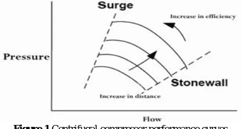
NTRODUCTIONAll manufacturers provide performance graphs for their compressors. The graph consists of one horizontal axis representing the flow rate (capacitance), one vertical axis representing the head or pressure, and a set of curves which indicate compressor performance in different turns.
Figure 1 Centrifugal compressor performance curves
As can be seen from Figure 1, there is a minimum and maximum capacitance point for each turn and the performance of compressor is stable and predictable between these two points. The maximum and minimum points are known as stonewall and surge respectively.
Connecting the surge points in different turns, we can obtain surge boundary line. When a compressor operates on the right side of this line its performance is in stable mode, while if it operates on the left side of this line it experiences instability or surge mode[1 - 3].
Surge is defined as instability in current flow which fundamentally occurs in the case of dynamic compressors. This phenomenon takes place when the compressor is unable to produce enough head-pressure required for overcoming downstream resistance, i.e. output pressure generated by compressor is lower than that of its downstream. Under such
Dynamic Simulation & Design of Fuzzy Logic
Active Controller for Controlling the Surge in
the Centrifugal Compressors
Qasem Abdollah Nezhad1, Jafar Ghafouri 2 and Mohammad Fathi3
1
Department of Mechatronics Engineering, Science and Research Branch, Islamic Azad University, Kurdistan, Iran
2
Department of Mechanical Engineering, Azad University, Tabriz, Iran
Volume 2, Issue 11, November 2013
Page 409
circumstances a reciprocating (cyclical) motion will be created in the gas flow.
By creating turbulences in the flow through, surge instability can lead to sudden damage of compressor vanes and hence to drastic reduction in its efficiency. There are two principal methods in dealing with the surge phenomenon in centrifugal compressors:
1. Velocity control method. 2. Using anti-surge control valves.
Paying close attention to characteristic curve of the compressor, we can infer that by lowering the turn we can be further away from the surge line. However, this method (velocity control) is not an effective way for this purpose and also speed reduction may not be accomplished quickly enough to prevent the surge phenomenon from happening. A typical example of a control system based on the velocity control method is schematically illustrated in Figure 2.
Figure 2 Surge control system based on speed control method
The most commonly-used method dealing with this issue is using anti-surge valves approach in which the control of surge process is realized through returning an amount of compressor output current back to its input by incorporating an Anti-Surge Control Valve (ASCV) or recycle valve. In this method when current flow is reduced and approximates the surge line a signal is transmitted from controller to anti-surge valve and causes it to open slowly and increase the flow slightly.
A drawback to this method is the fact that opening of this valve during the compressor normal operation results in undesired energy loss. Thus, appropriate provisions must be taken into account to keep the valve closed as possible provided that there is no risk of reaching the surge mode at the same time.
The valve needs to prevent the occurrence of surge not only during normal operation, but also when the compressor is going to begin or stop its operation.
During start-up stage the anti-surge valve acts as a bypass valve and makes the outgoing flow form compressor to return back to its inlet, because in the initial stages of start-up the compressor outlet is isolated from its downstream and the gas must reach the downstream prior to be compressed in order to enable the compressor to meet the defined head-pressure. When the output pressure reaches the desired level, the connection between compressor and its downstream is established and the gas flows toward downstream and simultaneously the valve shuts and the system resumes its normal operation. During normal stop stage the flow rate diminishes simultaneously as the turn decreases gradually to stop completely. However, in the case of emergency stop the anti-surge valve must reduce compressor head-pressure immediately.
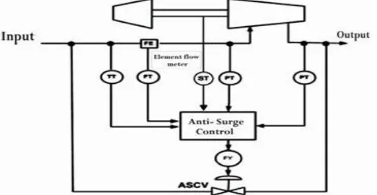
Typical configuration of surge control systems incorporating anti-surge valve is illustrated in Figure 3.
Volume 2, Issue 11, November 2013
Page 410
The measured values of compressor upstream and downstream pressure, passing gas temperature and flow rate, and speed of compressor axis form inputs of surge controller.
The role of surge controller in centrifugal compressor system is to open the anti-surge valve in the case of approximating the surge line in order to ensure the highest efficiency without jeopardizing compressor performance. In the present study the second method, using anti-surge valves, was adopted for the purpose of controlling the surge phenomenon[2, 4, 5, 14].
For the purpose of this study, after dynamic simulation of centrifugal compressor system the design of fuzzy logic active controller is investigated. The obtained results from simulation were compared for two modes (without controller and with fuzzy logic active controller) and repeated for five sample rates: 16000, 18000, 21000, 23000, and 25000 Rounds Per Minute(RPM). The sample rates were chosen randomly.
2. S
IMULATION OFC
ENTRIFUGALC
OMPRESSORS
YSTEMVarious models have been proposed in the literature of engineering field so far for explaining dynamic behavior of compressors. But we need to use a model which can meet the requirements of the present study. In other words, the selected model not only must provide an appropriate foundation for implementation of surge control system but also should have applicability to analyzing system dynamic behavior.
In the present study Greitzer model (developed in 1976) was applied to describe dynamic behavior of centrifugal compressors. Although this model was basically proposed for the case of axial compressors, founded acceptable results Pinsely (1989) and Willems (1991) demonstrated applicability of the model to centrifugal compressors[6, 7].
As can be seen in Figure 4, the compressor system is modeled as integrated with a tube (duct) of Lc length through which the compressed air is discharged into a voluminous chamber. This volume is generally known as Plenum in engineering literature. Compressor throttle is also modeled as a duct of Lt length through which the compressed air is guided toward compressor outlet.
Figure 4 Greitzer system model
In fact, the actuator disc inside the compressor duct acts as the major model of compressor and directs continuous flow current. The following assumptions are considered in design of Greitzer model:
The flow current passing through the ducts is unidimensional and incompressible.
The pressure is not distributed evenly inside the volume and the velocity of gas is negligible. The ratio of outgoing gas temperature to that of ingoing gas.
The effect of rotor speed variations on system behavior is negligible[8 - 10].
3. D
IMENSIONLESSM
ODEE
QUATIONSThe occurrence of surge phenomenon in centrifugal compressors is usually accompanied by certain features among which the followings are the most common:
Rapid reversal of compressor output flow of the order of milliseconds. Severe fluctuations in pressure.
Rapid increase in temperature of both passing gas and compressor interior. Sever vibrations which may lead to compressor slip.
Excessive noise.
Volume 2, Issue 11, November 2013
Page 411
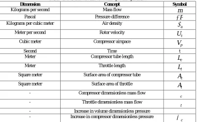
Table 1: Parameters involved in system dynamics
Symbol Concept
Dimension
m
Mass flowKilograms per second
P
Pressure difference Pascal a
Air densityKilograms per cubic meter
t
U
Rotor velocityMeter per second
p
V
Compressor airspace Cubic meter t Time Second cL
Compressor tube lengthMeter t
L
Throttle length Meter cA
Surface area of compressor tubeSquare meter
t
A
Surface area of throttleSquare meter
c
Compressor dimensionless mass flow-
t
Throttle dimensionless mass flow-
ψ Increase in volume dimensionless pressure
-
c
Increase in compressor dimensionless pressure-
Taking into consideration all parameters involved in dynamics of system and performing a dimensional analysis, we can obtain desired dimensionless parameters required for dynamic analysis of the system. Dimensional analysis results in dimensionless flow (Ø) and dimensionless pressure (ψ) which are expressed by relations (1) and (2).
t c a
A
U
m
(1)2
2
1
t aU
P
(2)For the purpose of obtaining dimensionless time(
t
~
)Greitzer founded the principle on the basis of Helmholtz frequency (
H). Relations (3) and (4) represent the issue.c p c H
L
V
A
a
(3)H
t
t
~
(4)
Applying classic thermodynamic and energy laws we have:
Flow rate variations between two sections are proportional to pressure variations between the very two sections. Now, if apply this law firstly between input and output of compressor and then between input and output of throttle relations (5) and (6) are resulted governing compressor flow through and throttle flow through respectively[3, 11, 12].
c
cB
t
d
d
~
(5)
C
t
G
B
t
d
d
~
(6)Volume 2, Issue 11, November 2013
Page 412
c H tL
U
B
2
(7)t c c t
A
L
A
L
G
(8)4. D
ESIGN OFF
UZZYL
OGICA
CTIVEC
ONTROLLERIntroducing fuzzy sets and concept of membership degree in 1965, Dr. Lotfali Asgarzadeh founded fuzzy logic.
Fuzzy systems are based on knowledge or principles and their core is a database consisting of then" rules. Fuzzy "if-then" rule is an "if-"if-then" expression the words of which are defined by membership functions. Fuzzy inference engine integrate these rules in the form of a representation from fuzzy sets to fuzzy sets in output space based on fuzzy logic principles. Fuzzy logic is used for design of expert systems. The expert systems in turn simulate real world laws. In this section centrifugal compressor system is equipped with fuzzy logic active controller[6, 13].
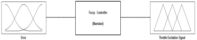
The fuzzy controller has been designed using graphical relation of fuzzy logic toolbox. The method adopted for this purpose is of Mamdani type. Figure 5 illustrates block diagram of Fuzzy Inference System (FIS).
Figure 5 Fuzzy Inference System block diagram
The designed fuzzy logic active controller system has one input and output, i.e. the error is considered as input parameter and the response to throttle excitation signal acts as output parameter. The membership functions of input and output are defined as of triangular type as can be seen in Figure 6. These functions are defined by verbal variables: (MF1), (MF2), (MF3), (MF4), (MF5), (MF6), (MF7), (MF8), (MF9), (MF10).
Figure 6 Type of input and output membership functions
Totally 10 membership functions have been defined for input and output, thus, 10 inference rules are required. Figure 7, illustrates these rules.
1 Out1 Input MF surge Output MF khoroj i Demux Demux Demux Demux Demux Demux Demux Demux Demux Demux > Zero Fi ring Strength? 0 T otal Firing
Strength Swi tch Rule Rul e9 Rule Rul e8 Rule Rul e7 Rule Rul e6 Rule Rul e5 Rule Rul e4 Rule Rul e3 Rule Rul e2 Rule Rule10 Rule Rul e1 -C-MidRange Demux COA Defuzzi ficati on1 max
A ggMethod1 1
In1
Volume 2, Issue 11, November 2013
Page 413
As shown in Figure 7, the number of blocks equal to fuzzy inference rules and the lines from and to these blocks represent relations associated with fuzzy logic rules. Input and output variables are depicted on left side and right side of the figure respectively. Trial and error method has been used for obtaining both input extent and applied fuzzy rules. The level of control for this system is illustrated in Figure 8.
Figure 8 System control level
Also, the simulated model for centrifugal compressor system equipped with fuzzy logic active controller is illustrated in Figure 9.
Figure 9 Simulated System Model
5. T
HEO
BTAINEDR
ESULTS FROMS
IMULATION OFC
ENTRIFUGALC
OMPRESSORS
YSTEM WITHOUTS
URGEC
ONTROLLERS
YSTEMSince the applied model in this study involves Greitzer compressional system as desired dynamic model for simulation and considering the fact that Greitzer has used dimensionless parameters of pressure and flow in mathematical model, the provided diagrams in the present study are presented on the basis of dimensionless parameters of pressure and flow. It is normal that the resultant diagrams form simulation performed in sections 5 and 6 are associated with five sample turns: 16000, 18000, 21000, 23000, and 25000 Rounds Per Minute(RPM). Each set of diagrams includes dimensionless flow fluctuations in terms of time, dimensionless pressure in terms of time, and dimensionless pressure in terms of dimensionless flow. Simulation time was defined as a five-second duration.
Figures 10, 11, and 12 show the results observed in simulation for sample turn 16000 Rounds Per Minute(RPM).
Volume 2, Issue 11, November 2013
Page 414
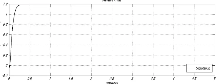
Figure 11 Dimensionless pressure diagram in terms of time
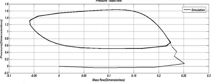
Figure 12 Dimensionless pressure diagram in terms of dimensionless flow
Figures 13, 14, and 15 show the results observed in simulation for sample turn 18000 Rounds Per Minute(RPM).
Figure 13 Dimensionless flow diagram in terms of time
Volume 2, Issue 11, November 2013
Page 415
Figure 15 Dimensionless pressure diagram in terms of dimensionless flow
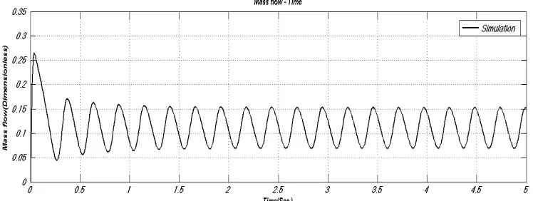
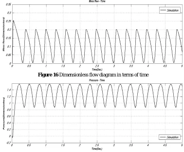
Figures 16, 17, and 18 show the results observed in simulation for sample turn 21000 Rounds Per Minute(RPM).
Figure 16 Dimensionless flow diagram in terms of time
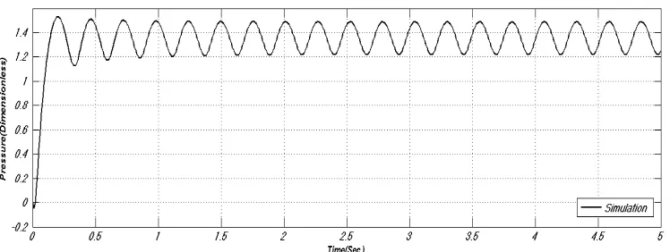
Figure 17 Dimensionless pressure diagram in terms of time
Figure 18 Dimensionless pressure diagram in terms of dimensionless flow
Volume 2, Issue 11, November 2013
Page 416
Figure 19 Dimensionless flow diagram in terms of time
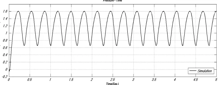
Figure 20 Dimensionless pressure diagram in terms of time
Figure 21 Dimensionless pressure diagram in terms of dimensionless flow
Figures 22, 23, and 24 show the results observed for sample turn 25000 Rounds Per Minute(RPM).
Volume 2, Issue 11, November 2013
Page 417
Figure 23 Dimensionless pressure diagram in terms of time
Figure 24 Dimensionless pressure diagram in terms of dimensionless flow
As can be observed, centrifugal compressor system experiences surge phenomenon when there is no surge control system incorporated into it.
6. T
HEO
BTAINEDR
ESULTS FROMS
IMULATION OFC
ENTRIFUGALC
OMPRESSORS
YSTEME
QUIPPED WITHS
URGEC
ONTROLLERS
YSTEMAs discussed in previous section, each set of diagrams includes dimensionless flow fluctuations in terms of time, dimensionless pressure in terms of time, and dimensionless pressure in terms of dimensionless flow, and Simulation time was defined as a five-second duration.
The observed results for simulation of centrifugal compressor system equipped with fuzzy logic active controller of surge are indicated for the cases of five sample turns: 16000, 18000, 21000, 23000, and 25000 Rounds Per Minute(RPM). Figures 25, 26, and 27 show the results observed for sample turn 16000 Rounds Per Minute(RPM).
Volume 2, Issue 11, November 2013
Page 418
Figure 26 Dimensionless pressure diagram in terms of time
Figure 27 Dimensionless pressure diagram in terms of dimensionless flow Figures 28, 29, and 30 show the results observed for sample turn 18000 Rounds Per Minute(RPM).
Figure 28 Dimensionless flow diagram in terms of time
Volume 2, Issue 11, November 2013
Page 419
Figure 30 Dimensionless pressure diagram in terms of dimensionless flow Figures 31, 32, and 33 show the results observed for sample turn 21000 Rounds Per Minute(RPM).
Figure 31 Dimensionless flow diagram in terms of time
Figure 32 Dimensionless pressure diagram in terms of time
Figure 33 Dimensionless pressure diagram in terms of dimensionless flow
Volume 2, Issue 11, November 2013
Page 420
Figure 34 Dimensionless flow diagram in terms of time
Figure 35 Dimensionless pressure diagram in terms of time
Figure 36 Dimensionless pressure diagram in terms of dimensionless flow
Figures 37, 38, and 39 show the results observed for sample turn 25000 Rounds Per Minute(RPM).
Volume 2, Issue 11, November 2013
Page 421
Figure 38 Dimensionless pressure diagram in terms of time
Figure 39 Dimensionless pressure diagram in terms of dimensionless flow
As can be seen, incorporating a fuzzy logic active controller of surge into the centrifugal compressor system, the occurrence of surge phenomenon is prevented effectively.
7. C
ONCLUSIONIn the present study the surge phenomenon is introduced as the most common and most critical instability in centrifugal compressors incident of which may leads to decreases in the system efficiency and certain failures in its mechanical structure. Greitzer model was investigated in dealing with simulation of compressor dynamic behavior, furthermore dimensionless equations governing system dynamics were derived on the basis of this model and considering the dimensional analysis. Then the focus of study concentrated on evaluating the simulation of centrifugal compressor system in two conditions (without controller and with fuzzy logic active controller). The obtained results for five sample turns (16000, 18000, 21000, 23000, 25000 (RPM)) were presented in sections 5 and 6. It should be noted that the criterion defined for assessment and comparison was stability of compressor.
Considering what was observed from this comparison we can conclude that under without-controller condition, system endures a complete surge and doesn't reach stability. On contrary, when a fuzzy logic active controller is incorporated into centrifugal compressor the occurrence of surge is prevented and system keeps its stability.
Finally, considering 5 proposed sample turns it can be obviously concluded that when centrifugal compressor system is equipped with fuzzy logic active controller the surge phenomenon can be easily prevented from occurring, whereas when centrifugal compressor system lacks such controller it will experience surge and cannot gain its stability. Therefore, these evidences confirm the importance and capability of fuzzy logic controller in preventing the occurrence of surge in centrifugal compressors, because severe fluctuations in pressure due to surge phenomenon may lead to continuous reciprocating displacement of rotor and consequently imposing additional loads on bearings particularly on axial load bearings. Depending on compressor rotation speed and bearing quality, after several times the surge phenomenon can cause failures in axial load bearing.
References
Volume 2, Issue 11, November 2013
Page 422
[2] D. Gysling, D. Dugundji, E. Greitzer, A. Epstein, "Dynamic Control of Centrifugal Compressor Surge Using Tailored Structures, " ASME J. Turbomachinery, 113(4), 710-722,1991.
[3] J. Pinsley, G. Guenette, A. Epstein, E. Greitzer, "Active Stabilization of Centrifugal Compressor Surge, " ASME J. Turbomachinery, 113(4), 723 – 732, 1991.
[4] K.K. Botros, J.F. Henderson, "Developments in Centrifugal Compressor Surge Control – A Technology Assessment," Transactions of the ASME Journal of Turbomachinery, April 1994.
[5] M.H. White, "Surge Control for Centrifugal Compressors," Chemical Engineering, Dec. 1992.
[6] A. Ashrafizadeh, "Surge Active Control through Fuzzy Logic in Axial Flow Compressors," Annual Conference on Mechanical Engineering, Eighteenth Session, P 1, Sahrif University of Thechnology, may 2010.
[7] B. Ribi, G. Gyarmathy, "The Behaviour of a Centrifugal Compressor Stage During Mild Surge," VID Berichte,(1186), 1995.
[8] F. Willems, "Modeling and Control of Compressor Flow Instabilities," Eindhoven University of Technology, pp. 96-151, 1997.
[9] F. Willems, B. De Jager, "Modeling and Control of Compressor Flow Instabilities," IEEE Control Systems, pp. 8-18, 1999.
[10]K. Hansen, P. JØrgensen, P. Larsen, "Experimental and Theoretical Study of Surge in a Small Centrifugal
Compressor, " ASME J. Fluids Engineering, 103(3), 391-395,1981.
[11]R.E. Sonntag, C. Borgnakke, G.J. Van, Wylen, "Fundamentals Thermodynamics," Sixth Edition, April, 2002. [12]F. Willems, B, De Jager, "One – Sided Control of Surge in a Centrifugal Compressor System," In Proc. of the
ASME Turbo Expo, Munich, Germany. Accepted for Publication, 2000.
[13]M.S. Taheri, "An Introduction to Fuzzy Sets Theory," Second Edition, Academic Jihad Publications, 1999.
[14]C. Meuleman, F. Willems, R. De Lange, B. De Jager, "Surge in a Low – Speed Radial Compressor ," ASME paper no. 98 – GT- 426,1998.
AUTHOR
Qasem Abdollah Nezhad was born in 1984, He received bachelor of Science in Mechanical Engineering from the Department of Mechanical Engineering, Islamic Azad University, Tabriz branch, Iran, in 2011, and Master of Science Mechatronics Engineering from the Department of Mechatronics Engineering, Science and Research Islamic Azad University, Kurdistan branch, Iran, in 2013. Currently he is a lecturer, He is the author of several papers in National Conference, His research interests includes robotics, mechatronics, image processing, control systems, fuzzy control application.
Jafar Ghafouri He received a BSs degree in Mechanical Engineering filed of Solids Design from Tabriz University, Iran, in 1999, and received MSs degree in Mechanical Engineering major field of Transformation of Energy from University of Science & Technology, Tehran, Iran, in 2001. In 2008, he got a PhD in the same major from Science and Research Islamic Azad University,Tehran Branch, Iran. He's now a member of Academic Board of Tabriz Azad University, iran, and assistant professor at the same place. The specific fields of research in which he's interested and has presented several articles include: internal combustion engines, combustion, heat transfer, CFD, smart systems and heat exchangers.