Volume 2, Issue 3, March 2013
Page 7
A
BSTRACTUse of optimum sized pellets makes the steel production process more reliable and energy efficient. The development of the vision based system to keep these pellets size in check is discussed in this paper, which involves integrating industrial grade IBM-PC with a high resolution industrial camera. We have applied this method to the pelletizing system in the Essar Steel Plant at Vishakhapatnam and made possible automated operation of the pelletizer.
Keywords: Vision System, Pellet, Size Distribution, Image Processing
1.
I
NTRODUCTIONThe Pellet Size Distribution System is a modular inspection system for the analysis and classification of the size and shape of pellets. The pellets are granulated materials and are made from fine ores through pretreatments with a pelletizer. It is known that there exists a high degree of correlation between the average size of pellets and the operating conditions of an electric furnace. Accordingly, pellet size control in the granulation process is indispensable for the stable operation of the furnace. According to the industry norms the size of pellets must be maintained between 9mm-16mm in diameter [1]. This size is analyzed and maintained in Pellet Size Distribution System, which is previously done manually and is not highly accurate. The vision based system is highly reliable and robust to be used in the industrial conditions. This paper outlines the method used and the system developed. A Disk pelletizer is a rotary tray with diameter of approximately 5 meters, inclined at an angle, as shown in Fig. 1. It rotates at a speed of 6-8 rpm. The pellet size is controlled by flow rate of water, speed of disk and angle fin inside disk. It is difficult to ensure accurate size control solely by visual inspection of human operators. Thus, there is a strong need for the development of system for measuring pellets continuously and accurately.
Figure 1 Disk Pelletizer
2.
Principle of Measurement
In order to ensure the accurate measurement in real time the pellet, partially as well as completely visible, in the top layer is analyzed. Pellet sizes are measured using a well-known algorithm, called Circular Hough Transform (CHT). Figure 2 shows the block diagram of the steps of the method followed.
Industrial vision system for distribution and size
analysis of pellets
Navdeep Singh, ShaliniSaxena, Dhiraj, J L Raheja
Volume 2, Issue 3, March 2013
Page 8
Figure 2 Block DiagramThe image is captured using a high resolution, high frame rate camera. The firewire port provides a link between camera and the PC. Basler scA640-70fm camera is used for this purpose, which provides IEEE 1394b (S800) port. Smoothing operation is done to remove the unwanted noise before processing. To complete this operation a low pass 2nd order Butterworth filter is used [2]. It is given by the formula shown in equation (1).
(1)
Where, n=Order of the filter, in this it’s value is 2. The result of applying the filter is shown in figure 3.
Figure 3 (a) Input Image (b) Smoothed Image
Edge Detection of the pellets in the image is required before we apply CHT. As it will be explained later, CHT,uses edge points to plot the center of the circles inscribing the pellets. We employ Sobel operator [3] shown in figure 4, where both horizontal and vertical filters are used. It uses 3x3 convolution masks, one for x-direction and the other one for y-direction. Euclidean sum is taken to get the final edges formula as given in equation (2).
(2)
Figure 4 (a) Horizontal (b) Vertical
Thresholding of the image is based on the present value of the gamma and gain setting of the camera. The gain and gamma settings of the camera are given on the front panel itself. Thethresholding method makes the process more dynamic and robust against the illumination changes. Figure 5 shows the result of applying the sobel mask over the image at discharge point.
Circular Hough
Volume 2, Issue 3, March 2013
Page 9
Figure 5 (a) SmoothedImage
(b) Edge Detection
After edges the edge directions and direction maps are calculated. This is done to reduce the number of calculations done over a symmetrical circle, as it can only be reduced to quarter of a circle [4]. Already calculated vertical edges and horizontal edges were used to calculate the direction using the formula as given in equation (3).
(3)
2.1.Hough Transform:
Hough transform is used for feature detection in automated analysis of digital images. The method is given the family of curves being sought (circles in this case) and produces the set of curves from that family that appear on the image [4]-[5].
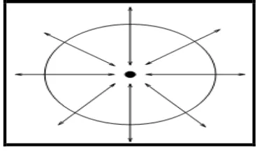
The method of Hough transform is that if a point lays on a circle then the gradient at that point, points to the center of that circle [8][9] as shown in figure 6. So, if numbers of edge points are given and range of radius is known and the direction of the vector from edge point to the center is computed, the coordinates of the center can be found [6]-[7].
Figure 6 Hough Method
The transform will create the maximum brightness at the probable centers. These probable centers can be spread over larger value of pixels, because of the range of radii. To concentrate these accumulated points we applied a 17x17 Laplacian of Guassian (LOG) filter [10]-[11]. LOG concentrates the highest brightness in the center of the accumulated space thus reducing the calculation afterwards. The result of applying Hough algorithm and then LOG filter are shown in figure 7.
Figure 7 (a) Result of applying Hough algorithm on image 5(b)
(b) Probable centers after applying LOG
Volume 2, Issue 3, March 2013
Page 10
Figure 8 (a) Centers afterlocal maxima
(b) Final output image with circles drawn
Since, there is need for better method than visual inspection of pellets, the radii results are plotted in a histogram and are displayed. The results can be analyzed to check the system at any instance. Also, the system control decisions are based on the value of these radii (i.e.the size of each pellet at any instance). In figure 9 the histogram of figure 8b is shown.
Figure 9 Histogram plot
2.2.Experimental Results
In order to evaluate the performance of the method, system was tested at the Essar Steel Plant, Visakhapatnam. The conditions of the test experiment are as follows:
(1) The testing was done at various RPM of disk Pelletizer.
(2) The method was tested both at center part and the discharging part of disk pelletizer.
(3) Light conditions were also varied as we wanted to test the robustness of our system against changes in illumination.
Figure 10 shows the size of the analysis of pellets at the discharge point of disk pelletizer running at the speed of 7.21 RPM. As it is shown most of pellets are restricted in the range of 9-16 mm in diameter.
Figure 10 Experimental Result 1 at 7.21 RPM
Volume 2, Issue 3, March 2013
Page 11
Figure 11 Experimental result 2 at 6.86 RPMThus with above results it can be concluded that the method can be applied to both the discharge part where the pellets are completely formed, and upper part, where the pellets are still in making. Also we tested the measurement error is ±1 mm.In order to test the effect of variations in illumination on the results, several test results were performed. Figure 12 shows the result of system at discharge point of disk pelletizer running at 7.21 RPM in very bad lighting.
Figure 12 Experimental result 3 at discharge point
Thus it can be concluded that the size index of the pellets is measured accurately and is not influenced by the variations in light.
2.3.Pellet Size Distribution System
An automatic Pellet Size Distribution and control system, to which the above method is applied has been made and is tested at Essar Steel Plant, Visakhapatnam.System architecture image is shown in figure 13.
Figure 13 System Achitecture
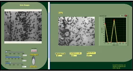
The system consists of a computer, which essentially an IBM PC with NI LabVIEW running, which is connected to a high speed firewire camera. An actual experimental setup at Essar Steel Plant, Visakhapatnam is shown in figure 14.
Volume 2, Issue 3, March 2013
Page 12
640x480 monochrome image
(4) Calculation Time: 1.93 sec
3.
Conclusion
We have described a new method for measuring and controlling the size of pellets with image processing techniques and automatic control system. A great advantage of the method is the offering of a huge variety of customized configurations to be applicable in for every objective perfectly. This includes a precise analysis and classification of the raw material.
References
[1] Pelletizing Technologies for Iron Ore, August. 2, 2010,Available : http://www.outokumputechnology.com/29696.epibrw
[2] Rafael C. Gonzalez and Richard E. Digital Image Processing. Upper Saddle River, New Jersey07458: Prentice Hall, 2002, pp. 167
[3] Rafael C. Gonzalez and Richard E., Digital Image Processing Using Matlab, Upper Saddle River, New Jersey, Prentice Hall, 2002
[4] Linda Shipro and George Stockman, Computer Vision, Upper Saddle River, New Jersey, Prentice Hall, 2000 [5] H.K. Yuen, J. Princen, J. Illingworth, J. Kittler. “Comparative study of Hough transforms methods for circle
finding.” Image Vision Computing, vol. 8, pp. 71–77, 1990
[6] Duda, R.O. and P.E. Hart. ”Use of Hough transformation to detect lines and curves in picture”. Communications ACM, vol. 15 pp. 11-15, 1972
[7] JagdishRaheja, V Upendranath, Rajesh M, P Bhanu Prasad, “Image Processing Techniques for Pellet Size Distribution.” in International Seminar on Mineral Processing Technology, Bhubaneswar, India, 2009
[8] Chester F. Carlson, Class Lecture, Topic: “Hough circle transform.” Rochester Institute of Technology, Henrietta, Rochester, October 11, 2005
[9] Kimme, C. D. Ballard and J. Sklansky. “Finding circles by an array of accumulators.” Proc. ACM., vol. 18 pp. 120-122, 1975
[10] Brinks R. “On the convergence of derivatives of B-splines to derivatives of the Gaussian function.” Computational & Applied Mathematics, vol. 27, 1 pp. 79-92, 2008
[11] Rafael C. Gonzalez and Richard E. Digital Image Processing. Upper Saddle River, New Jersey07458: Prentice Hall, 2002, pp. 583-585
[12] Lindgren, Georg. “Local maxima for Gaussian Fields.” Arkiv for MateMatik, vol. 10, pp. 195-218, 1972
AUTHOR
Navdeep Singh.has received his B. Tech from Lovely Institute of Technology, Jalandhar, Punjab, India. He worked as Project Assistant, in Central Electronics Engineering Research Institute (CEERI), Pilani, Rajasthan, in a national level project. His areas of interest are Real Time Image Processing and Human Computer Interface


