74
Copyright © 2018. IJEMR. All Rights Reserved.
Volume-8, Issue-2, April 2018
International Journal of Engineering and Management Research
Page Number: 74-78
Experimental Study on Micro Drilling Process
Ashirbad Swain1, C. Mohanty2, Rashmi Ranjan Panda3 and Dillip Mohanta4
1
PG Scholar, Department of Mechanical Engineering, Centurion University of Technology and Management, Odisha, INDIA
2,3,4Assistant Professor, Department of Mechanical Engineering, Centurion University of Technology and Management,
Odisha, INDIA
1
Corresponding Author: [email protected]
ABSTRACT
Micro-drilling processes have been widely used to produce micro holes such as micro dies and molds, fuel injection nozzles, watches, bearings and printed circuit boards. In this thesis all the available micro drilling technologies are reviewed. Whirling of the drill edge at the time of penetration into the work piece degrades hole quality as well. In order to measure circularity error, We requires the measurement systems such as optical microscope, and to measure drilling torque and thrust force, it is to be use of Dynamometer of Kistler (9272A). The way to optimize the DOE it is required orthogonal array. The orthogonal array of L 9 is used in this experiment.
Keywords— PMMA, Dynamometer, Micro machine
I.
INTRODUCTION
Micro-drilling processes have been widely used to produce micro holes such as micro dies and molds, fuel injection nozzles, watches, bearings and printed circuit boards etc. And it has more attention in a wide spectrum of
precision production industries. Experiments are
conducted to investigate the effectiveness of drilling processes by measuring the hole quality after micro-machining. As broadly classified in this paper, micro drilling operation is performed in two ways, conventional and non-conventional. The conventional technique refers to micro holing where a drill bit is mounted on the spindle and rotates at high speed, goes through the work piece and makes the micro hole. There are various types of micro drills depending on their shape and configuration.
The details of these types are discussed in subsequent sections. Recently, the trend for producing miniaturized products and devices that are “smaller, faster and cheaper” [1] has become the main focus in industries
such as electronics, aerospace, medicine and automobiles [2–4]. Miniaturized components such as PCB (printed circuit board), microscopic nozzles, micro dies and molds, chemical micro-reactors, tooth implantation, high-tech medical appliances, fuel filters and fuel ignition systems, are produced with the help of micro machining techniques [5–7]. Among those, micro drilling is one of the most fundamental micro machining techniques and is generally defined as the drilling of diameters between 1 μm and 1 mm. In line with the trend of miniaturization, micro drilling is now being extensively used in areas such as precision engineering, micro-electro mechanical systems (MEMS), micro total analysis (μTAS), consumer products, biomedical and chemical engineering, optical displays, fluidics, wireless and optical communications, and PCB industries [5,8–10]. Of all these industries, PCB makes the most use of micro drilling. As a key electronic component, a PCB requires hundreds, even thousands, of micro holes to connect the electronic parts according to a predetermined circuit design [11]. Driven by the continuously rising demand for smart phones, tablet computers and notebooks, digital cameras and video recorders, and other electronic devices, the PCB industry is growing very quickly world- wide. Research indicates that the PCB market is expected to grow with a compound annual growth rate (CAGR) of 4% over the period 2015– 2020 [12–15].
75
Copyright © 2018. IJEMR. All Rights Reserved.
orthogonal array. Here the work material is taken as
PMMA which has characteristics of transparent
thermoplastic and hence often used as a lightweight or shatter-resistant alternative to glass. Sometimes it is known as an acrylic glass. The sheet of 5 mm in thickness, 85 mm in length and 50 mm in width is to be considered in the experiment. The machine used in this experiment is Computer Numeric Control (CNC) system with carbide drill bit of 1mm diameter and having point angle 118° and 23 mm flank length.
The definition of micro drilling depends on the diameter of the hole. There is no specific standard to
define micro drilling. Different researchers and
manufacturers define micro drilling differently. Sphinx, the Swiss micro drill manufacturer, defined micro drilling as having a starting diameter of 0.05 mm and ranging to 2.5 mm [25]. Zhuang [26] defined a micro drill bit with a diameter less than 3.175 mm. Tibar et al. [27] defined micro drills as having a diameter less than 1 mm. Kudla in [28] defined micro drill with a diameter of less than 500 μm and in some other articles Kudla et al. [29] referred to a micro drill with a diameter less than 1 mm. According to Kondo et al. [30] the diameter of micro drills is less 1 mm. Robertson [31] stated that tooling suppliers defined a micro drill as being 1 mm in diameter. Zheng et al. [32] reported that the diameter of microdrills is generally between 0.03–1 mm. Abouridouane et al. [33] stated the diameter of drill in a micro range falls between d = 50 μm and 1 mm.
W.S. Chen [35] has investigated on the wear and performance of micro drills and presents series the influence of various factors on the efficiency of micro drilling process. He took micro drill geometry and cutting conditions as input variable along with drilling force, torque and drill wear as judging criteria. Computer controlled high speed drilling machine and piezoelectric dynamo meter (Kistler 9273) was used. The tool dia. is around 0.457mm with aspect ratio 17.5 on w/p material as printed circuit board was used for the investigation.
Hyon-ko-Sim [36] has conducted a study on condition monitoring process on glass by using machine. The experiment was carried out on w/p material as glass of 1mm thickness and drill bit used were diamond and carbide tools with 0.3 mm dia. In the paper, a precision 3D machine vision measurement system was intended to measure hole quality and inspect drill wear in microdrilling of glass material. It was found that Positional errors of fine holes, shape of cracks, and quality of hole surfaces are influenced by drilling conditions.
R. Vimal et. Al [37] [3] has Modeled and analyzed the Thrust force and Torque in drilling GFRP composites by multifaceted drill using fuzzy logic .The research has been made by taking Glass Fibre Reinforced Plastic using 8 facet solid carbide tool. 3 parameters such as spindle speed; feed rate and drill diameter with each having 3 levels using Taguchi L27 was used. Machine
used was ARIX-CNC Machine centre. Thrust force and torque were taken as judging criteria for optimization of input parameters. Fuzzy rule based model was developed to indicate thrust force and torque in drilling of GFRP composites. The results suggested that the model can be effectively used for predicting the response variable by means of which delimitation can be controlled.
P.F. Zhang[39] made a review on mechanical drilling process for titanium alloy which was based on micro drilling using different tools of diameter ranging from 0.05mm to 10mm with w/p material as Ti alloy. The paper presented a complete thorough review on conventional drilling processes for Titanium, namely, twist drilling, vibration assisted twist drilling, ultrasonic machining, and rotary ultrasonic machining. It discusses cutting force, cutting temperature, tool wear and tool life, hole diameter, cylindricity, surface roughness, burr and chip type as judging criteria while drilling of Ti using the mentioned processes.
Boris Stirn[40] has investigated the Burr Formation in micro drilling by using aluminum alloy and steel as W/p material with drill bit size 130μm, 250 μm and 500μm. machine parameters were diameter, cutting speed and feed rate where burr size and burr type were taken as the judging criteria. The influence of the cutting parameters on characteristic indices was observed and a comparison was being made.
Dong-Woo Kim et al. [41] reported
minimization of thrust forces in the step-feed micro drilling process. An orthogonal array of L27 was used to investigate the relationship between feed rate, step-feed, and spindle rpm with that of drilling Thrust. 2mm deep hole drilling process was minimized on the work piece of size 35*35*2.3. Dynamometer of Kistler made (9257A) was used to measure the thrust force. Author had found out optimal drilling conditions based on reliable experimental results to improve the productivity in micro drilling process.
Azlan Abdul Rahman(2009)[43] investigated the effect of feed rate, Spindle Speed, Drill bit diameter on material removal rate, Surface roughness, burr and dimensional accuracy by taking drill sizes of 0.5 to 1.0mm.
Comparative analysis was done between surface
roughness, MRR and accuracy of drilled holes by experimentation. Experimental result shows the increment of spindle speed and feed rate value mostly affects the tool wear and size of burr on the drilled hole edges.
II.
EXPERIMENT STUDY
Tool and Material In this study, PMMA (Poly
76
Copyright © 2018. IJEMR. All Rights Reserved.
and 1180 point angle and flute length is 23 mm.All the drilling was made using Radial drilling machine.
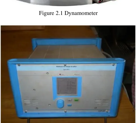
Dynamometer The Quartz 4 component
Dynamometer (type 9272A, Kistler made) along with Multi Channel charge Amplifier Type 5070 A was used for thrust force measurement. The Circularity and Burr Size were measured using SEM Pictures
Figure 2.1 Dynamometer
Figure 2.2 Multichannel charge amplifier
Workpiece
Mainly PMMA is a polymer of amorphous
thermoplastic material. Its IUPAC name is Poly methyl 2-methylpropenoate.
PROPERTIES:
Its molecular formula is (C5 O2 H8)n.
The glass transition temperature of purest form of PMMA material is nearly 115°C.
For injection moulding PMMA is processed at temperature from 210°C to 250°C and for extrusion process corresponding temperature is from 160°C to 200°C.
The melting point of PMMA is of 160°C (320°F)
and boiling point is 200°C (392°F).
Refractive index of PMMA is 1.4914 at
wavelength of 587.6 nm.
It is very high weathering resistance, high value of optical transparency and clarity retention with or without colourants.
It has low water absorption capacity and good impact resistance.
Polymer has good resistive capacity to weak acids and alkalis.
This can be solvent cemented.
Its shrinkage value is low i.e. from 0.4 % to 0.7%.
For improvement of impact strength, butyl
acrylate is mixed.
Drill Machine
Type--- Heavy duty drill (WDH type)
Company name--- Ralliwolf Limited, Bombay
(400080)
Serial No--- B913238 F/L amps--- 2.55A N/L RPM--- 560 rpm AC/DC volts--- 235V
Drill Bit
Type--- Solid carbide drill Diameter--- 1mm
Flute length--- 23mm Point angle--- 118°
Plan of Experiment
The Dynamometer was mounted over machine Bed having T-slot with the help of T-bolts of 10mm dia. and 80mm length and properly tightened with the help of washers and nuts. The PMMA Work piece was mounted on the dynamometer with the help of two Bolts having specification M8*15. The experiment was carried out without any coolant and air is used as natural coolant medium. During the experiment, the thrust force was measured with the help of dynamometer connected to multi channel charged amplifier.
In this experiment, two machining parameters having 3 levels each was taken as input parameter and thrust force was measured. Circularity was measured using Scanning Electron Microscope.
77
Copyright © 2018. IJEMR. All Rights Reserved.
III.
TAGUCHI METHOD
In determining the effectiveness of a design, we must develop a measure that can evaluate the impact of the design parameters on the output quality characteristics. This measure is introduced by Dr. Genichi Taguchi and called “Taguchi’s philosophy”. It is an efficient tool for the design of high quality manufacturing system. It is a widely accepted methodology for contemporary experiment design. The Taguchi method can optimize performance characteristics through the settings of process parameters and reduce the sensitivity of the system performance to sources of variation [48]. As a result, the Taguchi method has become a powerful tool in the design of experiment methods. In order to evaluate the optimal parameter setting, Taguchi method uses a statistical measure of performance called signal-to-noise (S/N) ratio that takes both the mean and the variability into account. Formerly, The S/N ratio was an electrical engineering concept defined as the ratio of signal power to noise power corrupting the signal. Taguchi expands this conception to the engineering system design area. The philosophy of Taguchi methods stresses that every engineering system is a man-made system, which employs energy transformation to convert input signal(s) into specific intended function. The ratio depends on the quality characteristics of the product/process to be optimized. The optimal setting is the parametric combination that results in highest S/N ratio. Usually, there are three categories of signal-to- noise ratios such as lower-the-better (LTB), the higher-the-better (HTB), and nominal-the-best (NTB) [49]. In this study, four responses such as material removal rate (MRR), tool wear rate (TWR), surface roughness (Ra) and circularity of machined component are considered. Two responses like surface roughness and tool wear rate are to be minimized
whereas two responses like material removal rate and circularity are to be maximized. Therefore, HTB and LTB categories of S/N ratios are dealt here.
IV.
CONCLUSION
The objective of this study was to find out the optimised combination of Feed and Spindle speed so that the thrust force can be minimized. The conclusions can be summarized as follows:
In the 1mm micro drilling process, the experimental work was carried out. By using Taguchi statistical method Optimal Parametric combinations were found out.
Taguchi method is one of the efficient methods for optimization of parameters where single response characteristics are considered.
78
Copyright © 2018. IJEMR. All Rights Reserved.
Thus, the optimal conditions are feed of 0.10mm/rev and spindle speed of 100 rpm.
REFERENCES
[1] Corbett J, et al. (2000). Nanotechnology: International
developments and emerging products. CIRP Annals
Manufacturing Technology, 49(2), 523–45.
[2] Ashish Bharti & S.K.Moulick. (2013). Parametric optimization of multi response factors in micro drilling operation. International Journal of Scientific & Engineering Research, 4(7), 1157-1163.
[3] Singh H. & Kumar P. (2006). Optimizing feed force for turned parts throughthe taguchi technique. Sadhana, 31(6), 671– 681.
[4] Thiren G. Pokar & Prof. V.D. Patel. (2013). Optimization and modeling of micro drilling process parameters. International Journal of Research in Modern Engineering and Emerging Technology, 1(2), 26-30. [5] Li BH, et al. (2014). Study on the stainless steel
1Cr18Ni9Ti micro-hole drilling experiment. Applied
Mechanics and Materials, 596, 43–46.
[6] Rahamathullah I & Shunmugam MS. (2013). Analyses of forces and hole quality in micro-drilling of carbon fabric laminate composites. Journal of Composite Materials, 47(9), 1129–1140.
[7] L.J. Zheng, C.Y. Wang, L.P. Yang, Y.X. Song, & L.Y. Fu. (2012). Characteristics of chip formation in the micro-drilling of multi-material sheets. International Journal of Machine Tools & Manufacture, 52(1), 40–49.
[8] Klocke F, Gerschwiler K, & Abouridouane M. (2009). Size effects of micro drilling in steel. Production Engineering, 3(1), 69–72.
[9] Kim DW, et al. Application of Design of Experiment method for thrust force minimization in step-feed micro drilling. Sensors 2008;8(1):211–21.
[10] Zheng,X., Dong,D., Huang,L., Wang,X., & Chen,M. (2013). Investigation of tool wear mechanism and tool geometry optimization in drilling of PCB fixture hole.
Circuit World, 39(4), 195–203.
[11] Liang X, et al. (2015). Mechanical drilling of PCB micro hole and its application in micro ultrasonic powder molding. Circuit World, 41(2), 87–94.
[12] Shi,H. & Li,H. (2013). Challenges and developments of micro drill bit for printed circuit board: A review.