w w w . i j m r e t . o r g I S S N : 2 4 5 6 - 5 6 2 8 Page 1
Printing Roll Manufacturing using Laser Scanner
Heeshin Kang
1, Jiwhan Noh
2 1, 2(Department of Laser & Electron Beam Application/ Korea Institute of Machinery & Materials, Korea)
ABSTRACT :Research for the development of the roll-to-roll printing process in lieu of the existing semiconductor process is actively underway. The roll-to-roll printing system can enable electronic devices to be mass-produced at low cost. This study was conducted to develop the manufacturing technology of the printing roll used in the printing process of electronic devices. The indirect laser engraving technology was used to create printable roll made of chrome-coated roll after coating the surface of the steel roll with copper and polymer, ablating the polymer on the surface of the roll, and etching the roll. The 3-dimensional laser scanner and roll rotating systems were constructed, and the system control program was developed. We used 100W-grade fiber laser, 3-dimensional laser scanner, and 3-axis moving stage system with a rotating axis. We derived the optimal conditions by performing laser patterning experiments, and we were able to secure the minimum line width of 24
㎛
by using the developed 3-dimensional laser scanner system.KEYWORDS -3-dimensional, laser, scanner, roll, printing, patterning
I. INTRODUCTION
Most manufacturers currently produce electronic devices in the wafer-based semiconductor process, which requires high-priced equipment and robust process technologies. Therefore, it is essential to develop an alternative semiconductor process that can mass-produce electronic devices at low cost. To this end, researches are ongoing to study the processes for the mass production of electronic devices based on the roll-to-roll printing process, which is a conventional mass-printing method. The roll-to-roll printing method has drawn attention because the process technology can mass-produce secondary semiconductors such as RFID tag, electronic paper, solar cell, and smart sensor at low cost. Commercializing such production method requires two technologies of printing equipment: conductive ink and conductive polymer. The process of printing electronic devices using a printing roll requires a technology for processing the printing roll. The printing roll processes include flexo printing, offset printing, screen printing, and gravure printing.[1,2] The processes of manufacturing gravure printing roll include electronic sculpture, indirect laser engraving, and direct laser engraving.[3,4] As the leading technology today, the indirect laser engraving technology involves coating the printing roll
surface with polymer or black paint, patterning the electronic device circuit using laser beam, and etching the circuit on the roll surface through the etching and coating processes. Since the degree of integration of printed electronic device has been increasing, the line width and spacing of the printing roll pattern have been decreasing. Therefore, there is growing demand for the printing
roll patterning process to produce 20 ~ 30 ㎛, but
there has yet to be a system that can flawlessly yield the micro line width.
This study developed the indirect laser patterning technology and laser processing system using a 3D laser scanner to process the printing roll with micro line patterns and conducted a laser patterning test. The 3D laser scanner patterning test observed the micro line widths with optical microscope to deduce the optimal laser condition. It also studied the technology for improving the precision of the laser patterning system using a 3D laser scanner.
II. TEST APPARATUS AND METHOD
w w w . i j m r e t . o r g I S S N : 2 4 5 6 - 5 6 2 8 Page 2 laser patterning system used in the test to check
various patterns.
(a)
(b)
(c)
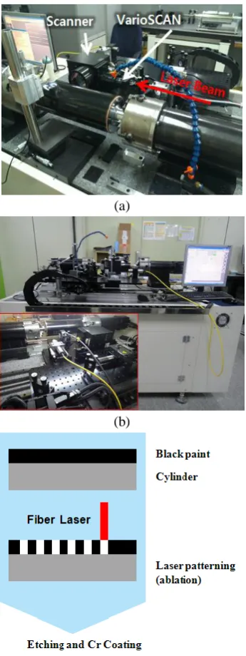
Fig. 1. Indirect laser patterning for manufacturing the printing roll; (a) polymer-coated roll (b) laser patterning system (c) manufacturing process
Manufacturing a printing roll patterned with the intended shape requires creating the pattern with a CAD program first and removing the black polymer on the roll surface by emitting laser using the 3D laser scanner in the same shape as that created by the CAD program. Fig. 1(c) illustrates the process of final manufacturing of a printing roll through the etching and plating process after laser patterning on the roll coated with polymer. Plating the steel base roll with copper at the beginning of the printing roll manufacturing process improves
the coating performance and corrosion resistance of polymer after laser patterning. The post-processing adds final chrome plating after the corrosion process to increase the strength of the roll surface during printing before finalizing the printing roll. Table 1 lists the main specifications of the laser patterning system, process variables, and main components of black polymer coating the roll coated with copper.
Table 1. Specifications of the laser patterning system
Laser Power 100 W
Laser Wavelength 1070 nm
Focal Length of F-theta Lens 80 mm
Diameter of Beam Spot 20 ㎛
Moving Stage XY table
Rotating Speed 20 rpm
Diameter of Printing Roll 125 mm
Thickness of Copper Coating 250 ㎛
Thickness of Black Polymer 3~4 ㎛
Thickness of Chrome Coating 6~7 ㎛
Chemical Name & Common
Name Contents (%)
Acryl Groups Resin 9.0-11.0
Inorganic Pigments 4.5-5.5
Propyleneglycol Mono Ethyl
Ether 21.0-23.0
Isopropyl Alcohol 3.0-5.0
Toluene 8.0-10.0
Methyl Ethyl Ketone 12.0-14.0
w w w . i j m r e t . o r g I S S N : 2 4 5 6 - 5 6 2 8 Page 3 Among the main system components, the laser
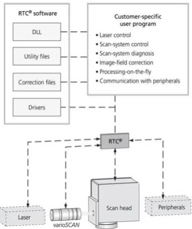
oscillator uses 100W-grade fiber laser system, whereas the moving unit consists of the X-Y table, roll rotating axis, 3D laser scanner, and optical module. It uses the 3D laser scanner system instead of the laser head moving unit to create an arbitrary pattern in the 10 x 10 mm section since it enables high-speed patterning. The scanner type has many advantages over the head moving type because of the continuity and repeatability of the pattern. We developed the 3D laser scanner-based system for printing roll laser patterning using 3D laser scanner, scanner oscillation unit, and interface with the moving axis. Fig. 2 shows the block diagram of the 3D laser scanner system. The varioscan that enables transport along the z-axis according to the variation of roll curvature can emit laser beam with constant focal distance even when the scanning distance changes.
Fig. 2. Diagram of the 3-dimensional laser scanner system
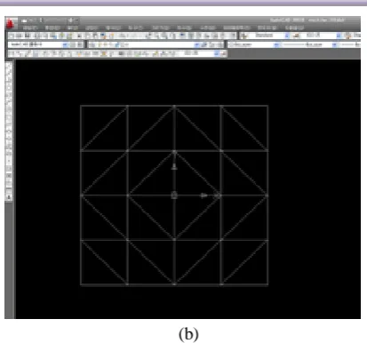
Fig. 3 presents a picture of the 3D laser scanner system. The z-axis moving distance that compensates the focal distance for varying roll curvature is ± 4 mm, and the maximum moving speed is 1m/sec. The image area of the F-theta lens is 47 x 47 mm, whereas the focal distance is 80 mm. The aperture is set to 14 mm. Fig. 4 shows a page of the control software of the processing system of the laser scanner-based printing roll. The software has functions such as laser control, scanner system control, processing system movement control, coordinate data extraction from CAD files, and configuration parameter setting.
Fig. 3. 3-dimensional laser scanner system with z axis
Fig. 4. Window of system control software
w w w . i j m r e t . o r g I S S N : 2 4 5 6 - 5 6 2 8 Page 4 Fig. 5. Experimental conditions for 3-dimensional
laser scanner engraving by power, speed, and position
Table 2. Experimental conditions
(a)
(b)
Fig. 6. Patterns for manufacturing the printing roll; (a) for power condition (b) for speed condition
III. TEST RESULT
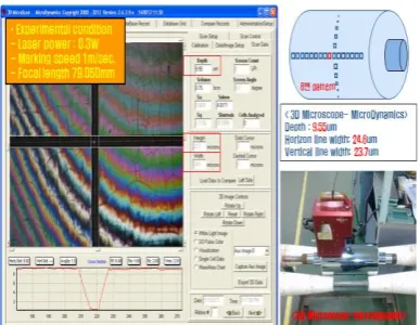
The basic test varied the laser output, patterning speed, and focal length and repeated the condition of laser output of 0.3 W, patterning speed of 1m/sec, and focal length 79.050 mm to produce the minimum line width. Instead of the conventional polymer photo-curable method using UV laser, we used the black polymer coating method since it has no development process. The process involved spraying black polymer on the surface of the steel roll with copper coating and emitting laser in the specified pattern to remove the black polymer. After the laser patterning process, the final printing roll was manufactured through the etching and chrome coating processes.
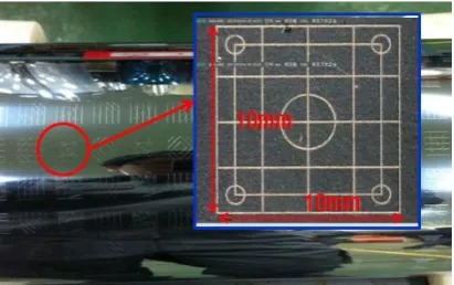
Fig. 7 shows the measurement of the line widths of the 10 x 10 mm pattern using 2D microscope after passing the black polymer-coated roll through laser patterning, etching, and chrome coating processes. Fig. 8 presents the measurement of line widths and depth using 3D microscope. The
minimum line widths were 24.6㎛and 23.7 ㎛for
the horizontal line and vertical line, respectively,
w w w . i j m r e t . o r g I S S N : 2 4 5 6 - 5 6 2 8 Page 5 Fig. 7. Measurements of line width after laser
patterning, etching, and chrome coating
Fig. 8. Measurements of line width and depth after
chrome coating (horizontal line: 24.6 ㎛, vertical
line: 23.7 ㎛, depth: 9.55 ㎛)
Fig. 9 presents the observation result of line width change according to laser output. The test condition included patterning speed of 1 m/sec and focal distance of 79.050 mm under laser outputs of 0.3, 0.6, 1.0, and 1.4 W. Both horizontal and vertical lines were found to have changed inversely as the output increased.
(a)
(b)
Fig. 9. Measurements of line width by laser power; (a) microscope image (b) graph by power
Fig. 10 shows the observation result of line width change according to laser output. The test condition included laser output of 0.3 W and focal distance of 79.050 mm under patterning speeds of l30, 200, 600, and 1,000 mm/sec. Both horizontal and vertical lines were found to have changed proportionally as the speed increased.
w w w . i j m r e t . o r g I S S N : 2 4 5 6 - 5 6 2 8 Page 6 (b)
Fig. 10. Measurements of line width by patterning speed; (a) microscope image (b) graph by speed
Fig. 11 shows a magnified picture of the 10 x 10 mm pattern shape produced from the roll with black polymer coating using the 3D laser scanner.
Fig. 11. 10 x 10 mm pattern on the manufactured printing roll using the 3-dimensional scanner system (laser power: 0.3 W, speed: 1m/sec, focal length: 79.050 mm)
IV. CONCLUSION
This study investigated the process of manufacturing the printing roll using a 100W-grade fiber laser with wavelength band of 1070 nm. The test adopted the indirect laser patterning that used black polymer coating.
The test result according to laser output and patterning speed showed that the line width of the pattern changed proportionally when only the
laser output increased and changed inversely when only the patterning speed increased, with all other conditions remaining the same. The precision electronic printing rolls currently require line
widths of 20 ~ 30 ㎛and depth of about 10 ㎛. The
test result of this study showed minimum line
width of 23.7 ㎛and pattern depth of 9.55 ㎛(Fig.
8). The optimal condition for the laser patterning of the printing roll was laser output of 0.3 W and patterning speed of 1 m/sec. A laser patterning test using a laser scanner with 10 x 10 mm working area was conducted, with precise square patterns and circular patterns fabricated.
We intend to improve system performance and increase precision by analyzing the result of the investigation of process and system obtained through this study. Furthermore, we will continue the development of the control software with focus on increasing productivity.
REFERENCES
[1] B.O. Choi, D.S. Kim, T.M. Lee, C.H. Kim, M.H. Lee and G.J. Lim, Study on the roll printing process for fine line-width printing, The Korea Society of Mechanical Engineering, Fall Conference Lecture and Journal, 2005, 2377-2381.
[2] JeongSeo, Laser plate marking of R2R printing roll for printed electronic device, Optical Society of Korea, Optics and Technology, 13(4), 2009, 25-31.
[3] H.G. Sohn and JeongSeo, Direct/indirect laser patterning of printing roll for printed electronics, Korea Society for Precision Engineering, Journal of 2008 Spring Conference, 2008, 399-400.
[4] S.R. Goh, Gravure printing roll processing technology, The Korea Society of Mechanical Engineering, Journal of KSME, 49(8), 2009, 37-40.
[5] S. J. Seok, Laser micro-patterning software development for manufacturing of pattern roll for printed electronics,2013 IEEE 22nd International Symposium on Industrial Electronics, ISIE 2013, Article number 6563740, 2013.