Research Journal
Volume 7, No. 19, Sept. 2013, pp. 36–40
DOI: 10.5604/20804075.1062353 Original Article
Received: 2013.06.12 Accepted: 2013.08.07 Published: 2013.09.06
COMPARISON OF GEOMETRIC PRECISION OF PLASTIC COMPONENTS
MADE BY SUBTRACTIVE AND ADDITIVE METHODS
Paweł Fudali1, Waldemar Witkowski1, Dawid Wydrzyński1
1 The Faculty of Mechanical Engineering and Aeronautics, Rzeszow University of Technology, al. Powstańców
Warszawy 8,35-959 Rzeszów, e-mail: [email protected]; [email protected]; [email protected]
ABSTRACT
The paper presents information on manufacturing processes of plastic components. Basic subtractive and additive methods are described. There were also manufactured elements of fan housing by using this two types of methods. Then, the elements were measured using a touch probe. The obtained results were analyzed, on which a com-parison of components’ geometric accuracy was performed.
Keywords: rapid prototyping, fused deposition modelling, machining, touch probe measurement, points cloud.
INTRODUCTION
The manufacture of plastic components is currently dominated by injection moulding. The method is suitable for mass production because the time of a single piece is very short. Howev-er, the preparation process, the production of the punch, die and tooling is very time-consuming and costly. In many cases, we need to make in-dividual elements, in this case, it is reasonable to apply the additive and subtractive methods. The article focuses on two methods of preparation of plastic components. Two identical parts were
made, the first one by fused deposition modelling
(FDM) method and the second by milling. Both elements were compared from the point of com-plexity and the results obtained.
SUBTRACTIVE AND ADDITIVE
MANUFACTURING
Subtractive manufacturing is a process in
which a piece of material is cut into a final shape
and size by a material-removal process.
Subtractive manufacturing can be divided into: • machining,
• chip machining,
• abrasive machining, • erosion machining.
Depending on the desired shape and rough-ness of the surface there are used different types and methods of machining. They differ between themselves in used tools and the nature of the movements which perform the tool and the work-piece [1, 2].
The principal machining processes are turn-ing, millturn-ing, borturn-ing, drillturn-ing, sawturn-ing, shapturn-ing, planing, and grinding. Except those mentioned machining methods, others such as reaming, countersinking, broaching, honing and lapping are known. Depending on the accuracy, shape and size of the work surface, there are the
follow-ing types of machinfollow-ing: coarse, fine and very fine, called finishing.
The term additive manufacturing refers to the production technologies that create objects through a sequential layering process. Elements that are manufactured additively can be used anywhere during the product life cycle, from pre-production (rapid prototyping – RP) to full-scale production (rapid manufacturing – RM), in addi-tion to tooling applicaaddi-tions.
(SLA), 3D printing (3DP), Electron Beam Free-form Fabrication (EBF), Direct metal laser sin-tering (DMLS), electron beam melting (EBM), selective heat sintering (SHS), selective laser sintering (SLS), Laminated object manufacturing (LOM), Digital Light Processing (DLP) etc.
Rapid Prototyping is an additive technology which is capable of providing a physical model of the designed object from a 3D model in CAD sys -tem. Regardless of which method will be used to make an actual element, CAD model is converted to STL format, which is an informal language of this technology. Then, a transverse division of model into layers is conducted, the thickness of which, in the case of FDM technology, depends on the size of the nozzle used for part construc-tion (0.127–0.33). Real-time execuconstruc-tion of Rapid Prototyping methods is disproportionately short -er than standard machining. This methods create both illustrative models and functional elements, used directly in the construction of machines or equipment and those that are used for example in a foundry [6].
Models are made of thermoplastic materials. Most materials used in model manufaturing are PC (Polycarbonate), ABS (acrylonitrile – buta-diene – styrene), and their modification example ABSI (methyl methacrylate ABS) and mixtures.
FDM METHOD
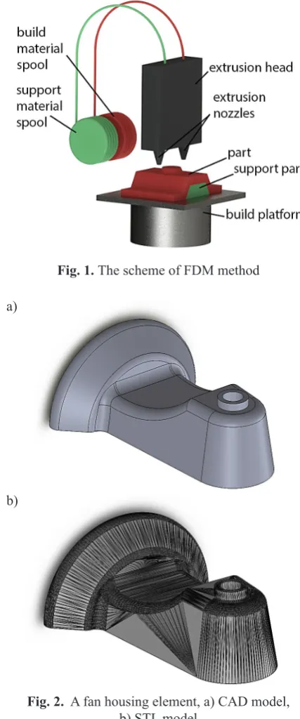
One of the method of rapid prototyping is FDM (Fused Deposition Modeling). FDM is a technique involving the extruded deposition of plasticized model and supporting material with two-nozzle head. The material is deposited on a working platform, which decreases gradually with a coating of plasticized material (in a form of filaments) forming the model in accordance with the arrangement of successive layers of a virtual STL model. Nozzle during imposing plasticized material moves over the platform in the XY plane, and the platform moves along the Z axis [6]. The scheme of the method is shown in Figure 1.
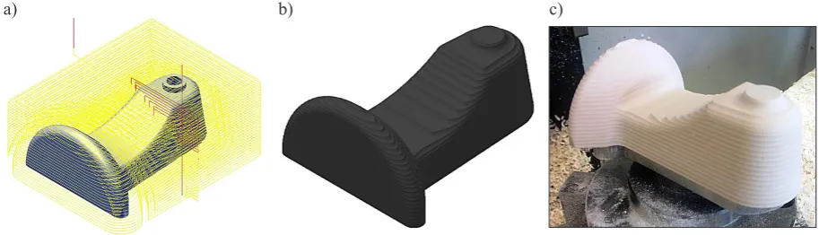
As a part of this work a fan housing element was made in FDM technology. Figure 2a illus-trates a CAD model of the considered element prepared in SolidWorks program, and in Figure 2b the same model with superimposed grid saved in STL format is presented.
Then the STL file was exported to the device in which it was manufactured. Figure 3 shows the final element.
Fig. 1. The scheme of FDM method
Fig. 2. A fan housing element, a) CAD model, b) STL model
Fig. 3. Element made in FDM method a)
MILLING
Virtual model has been saved in data ex -change format (.STL). An integrated CAD/CAM software (Inventor/HyperMILL) was used for preparing the machining simulation. The advan -tage of the integration of CAD-CAM systems is the ability to make changes of the detail design features with automatic updates designed ma -chining paths (no need to re-define them).
Subsequent machining operations, the pa -rameters and the used tools are shown in Table 1. Operations from 1 to 2 are roughing operations, while others are finishing.
Table 1.Machining operations, parameters and tools
No Operation (HyperMill) Tools The machining parameters
1. Rough End mill Ø16 S = 3000 [rpm]
f = 5000 [mm/min] ap = 2 [mm]
machining allowance 0.15 [mm]
2. Rough
End mill Ø8 3. Flat
S = 3000 [rpm] f = 5000 [mm/min] ae = 0.1 [mm] (distance
between paths) 4. Naba sides
5. Steep Shell end mill Ø16
6. Foot Ball end mill Ø8
7. Ridge
8. Rounded Ball end mill Ø4
9. Steep Ball end mill Ø4
Examples of roughing path (machining oper-ation number 1) are shown in Figure 4a. For this operation, Figure 4b shows the appearance of the blank after the machining. Prepared motion tools path were used to create NC code.
The part was machined on the CNC HAAS VF2 milling machine. Modeling disc was used as a blank. The mechanical and physical properties of the semi-finished product, are given in Table 2. CAD model after the virtual machining simu -lation and real part after machining are shown in Figure 5.
ANALYSIS OF THE COMPONENT
ACCURACY
Both parts (machined and FDM model) were mounted on the CNC machine (V2 HAAS). Using the touch probe (RENISHAW OMP40-2) points on the objects were measured. While measuring flat surfaces perpendicular or parallel to the direc-tion of measuring NC driver software automati -cally compensates the contact coordinates of the measuring ball radius [2].
The problem during the measurement of the surface at an angle is that the machine controller, depending on the direction of approach (perpen-dicular or parallel to the Z-axis) compensates the coordinates of the measuring tip along the feed axis (Fig. 6) [2]. The solution of this problem would be:
• rotation of the model in A, B or C axis (if ma-chine allows to control this axis) by an angle of slope of the wall (which must be known) so that the measuring ball in contact with the object along the normal to the surface being measured [3, 5];
• use the correction methods (method of cross-product, cross-product method using weight-ing factors, the method uses a distance crite
-Fig. 4. Roughing model a) after path generation, b) after machining simulation, c) after milling
a) b) c)
Table 2. Mechanical and physical properties of the modelling disc material
Material
name Color Shore hardness strength [MPa]Compressive Bending strength [MPa] [kg/dmDensity 3] temperature [Heat deflection 0C]
rion to select neighboring points) when free surfaces are measured [7].
The points cloud from the measured model were imported into CATIA. In this environment, they were changed into surfaces representing the model [4]. The side surfaces of the object were shifted by the radius of the ball in the direction of the measuring probe directions to the model.
A comparative analysis of the real geometry of the model and the reference model was made. Referenced model was a CAD model in STL for -mat, used to create a machining program and the implementation of a rapid prototyping method.
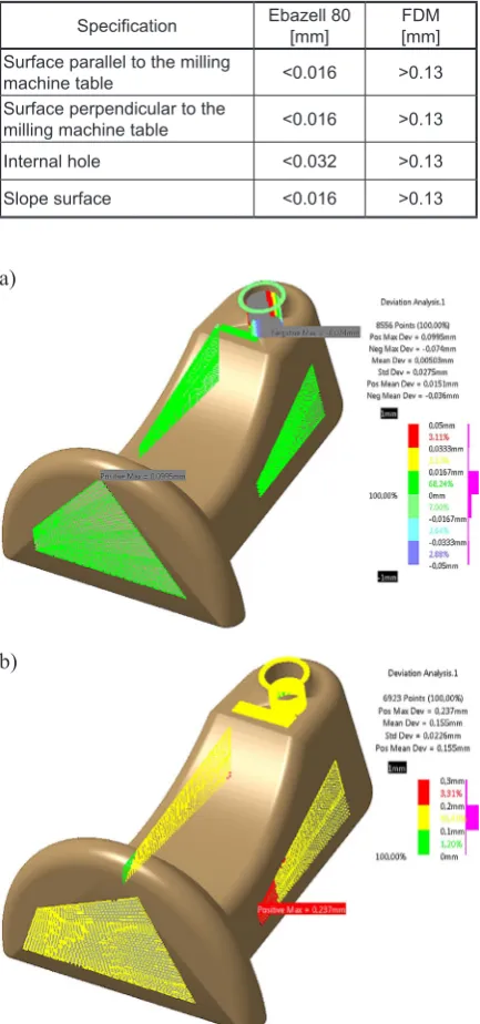
The results of the analysis are shown in Fig -ure 7. In Table 3 the maximum absolute values of the differences between the model and the actual model are shown.
On flat surfaces the measuring area was de-fined (Fig. 7). During measuring on the rounded surfaces the measuring head can be easily dam -aged because of its bending. Measurement of the hole consisted of determining the diameter at dif -ferent depths and the position of its axis.
Fig. 5. The model after virtual machining simulation in program HyperMILL and after the milling
Fig. 6. Measured point on slope walls
Table 3. Accuracy of the performed models
Specification Ebazell 80[mm] FDM[mm]
Surface parallel to the milling
machine table <0.016 >0.13
Surface perpendicular to the
milling machine table <0.016 >0.13
Internal hole <0.032 >0.13
Slope surface <0.016 >0.13
Fig. 7. Analysis of the accuracy of geometric object
made in a) subtractive method, b) additive method a)
CONCLUSION
Basing on our studies we can conclude the following:
• model made in machining (milling) have smaller errors than the object made in an ad -ditive method,
• model geometry errors made in additive meth -od are largely due to the thickness of the mate -rial layer,
• curved surface measurement using the probe is not possible due to the nature of measure -ment (pressure of measuring ball causes de-flection of the probe and its further movement would cause measuring head damage),
• performance of individual item made by ma -chining is much more labour-intensive (CNC machine and machining program are required) than in FDM method (FDM ~126 min, ma-chining ~150 min),
• accuracy measurements directly at the milling machining (in one fixing) allow to avoid an er-ror in determining the base and allow dimen -sional control during processing,
• both methods are ideal for the production of a single prototype.
REFERENCES
1. Chen J., Ling C.: Improving the machine accuracy through machine tool metrology and error correc -tion, Advanced Manufacturing Technology, 11,
1996, 198–205.
2. Dornfeld D., Dae-Eun L.: Machine design for pre-cision manufacturing. In: Prepre-cision
Manufactur-ing. Springer Verlag, USA 2008.
3. Hsu Y.Y, Wang S.S.: Mapping geometry errors of five-axis machine tools using decouple method.
Int. Precis. Technol., 1, 2007, 123–132.
4. Hylewski D.: Próba weryfikacji metody doboru pa-rametrów digitalizacji powierzchni swobodnej dla celów inżynierii odwrotnej w systemie CATIA V5. Wyd. Politechniki Poznańskiej, Poznań 2011.
5. Uddin M., Ibaraki S., Matsubara A., Matsushita T.:
Prediction and compensation of machining geometric
errors of five-axis machining centers with kinematic
errors. Precision Engineering, 33, 2009, 194–201. 6. Budzik G.: Odwzorowanie powierzchni
krzywolinio-wej łopatek części gorącej silników lotniczych w pro-cesie szybkiego prototypowania. Oficyna Wydawni-cza Politechniki Rzeszowskiej, Rzeszów 2009.