
1
Frontiers in Heat and Mass Transfer
Available at www.ThermalFluidsCentral.org
DEVELOPMENT OF A 10 KW MICROWAVE APPLICATOR
FOR THERMAL CRACKING OF LIGNITE BRIQUETTES
Benjamin Lepersa,∗, Thomas Seitza, Guido Linka, John Jelonneka,b, Mark Zinkc
a
Karlsruhe Institute of Technology, Institute for Pulsed Power and Microwave Technology (IHM), Eggenstein Leopoldshafen, 76344, Germany
b
Karlsruhe Institute of Technology, Institute for Highfrequency Techniques and Electronic (IHE), Karlsruhe, 71131, Germany
c
TU Bergakademie Freiberg, Institute of Energy Process Engineering and Chemical Engineering (IEC), Fuchsmuehlenweg 9, 09599 Freiberg, Germany
ABSTRACT
A compact10 kWmicrowave applicator operating at2.45 GHzfor fast volumetric heating and thermal cracking of lignite briquettes has been suc-cessfully designed and tested. In this paper, the applicator design and construction are presented together with a sequentially coupled electromagnetic, thermal-fluid and mechanical Comsol model. In a first step, this model allows us to calculate the power density inside the lignite material and the temperature distribution in the applicator for different water flow rates. In a second step, the total stress due to the thermal dilatation, the internal pressure inside the ceramic and the contact pressure from the seals at both ends of the ceramic can be computed. In addition, preliminary experimental results are given and showed a significant mechanical strength weakening of the briquettes with microwave heating.
Keywords:Microwave applicator, microwave heating, thermo elastic model, silicon nitride, lignite, thermal cracking
1. INTRODUCTION
In the framework of a collaborative project between IHM from KIT and IEC from TU Bergakademie Freiberg for microwave heating of lignite briquettes, a10 kWcompact applicator operating at2.45 GHzhas been successfully designed and tested. This applicator delivers volumetric heating to the briquettes which are moving inside a microwave transpar-ent ceramic silicon nitride tube with high mechanical strength. Upstream to this applicator, briquettes are produced from the lignite coal powder with a briquetting press machineRosinet al.(2014). Downstream of this applicator, after being heated by the microwave field, the briquettes are moving toward the gasifier for syngas (mixture of hydrogen and carbon monoxide) production for example. This system allows the transfer of lignite material from the production machine to the gasifier with pressure up to65 bars. Innovative feeding systems for pressurized gasification reactors are currently being developed by TU Freiberg Bergakademie. Important requirements for such systems are a simple design and high re-liability. The briquetting press is a continuously operating machine with mass flow up to25 t/h. The sealing between the briquetting machine and the gasifier is made by the briquettes plug in the feed channel. It makes the briquetting press a self sealing systemRosinet al.(2014).
With fast microwave volumetric heating (the moving briquettes crosses the ceramic tube in9 sand passes in front the rectangular aperture in2 s, at the production rate75briquettes per minute), thermal cracking was observed together with an increase of the briquette friability. Volumet-ric heating induces thermal cracking and can be used as a thermal pre-treatment to reduce the energy requirement for grinding or can be used directly as a communition tool (i.e desctruction, breakage) for the lignite
∗
Corresponding author. Email: [email protected]
materialBatar(2004). High power microwave heating of coal with expo-sure time of few seconds increases significantly the grindabilityBinner
et al.(2014), and consequently is beneficial for the overall efficiency of the gasifier. Microwave heating of lignite is much faster than conventional heating of coalPickleset al.(2014) (with the valuer = 5.48−0.73j for fresh lignite, the skin depth is about6 cm). This work presents the design of a microwave applicator used for continuous volumetric heating of lignite briquettes together with a Comsol multiphysics model used to calculate the power density, temperature, displacement and stress field in the applicator parts. In addition, some first experimental results are given.
2. THE APPLICATOR DESIGN
Fig. 1Aluminum block Alumec 100 with the ceramic silicon nitride and the graphite seal, the M22 thread insert are visible
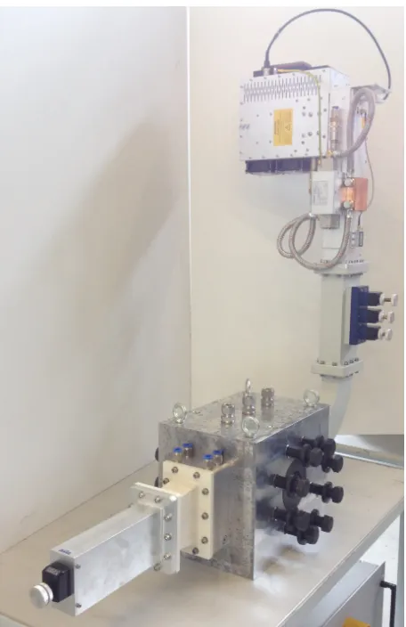
Fig. 2Applicator with magnetron, manual tuner, aluminum bloc, silicon nitride ceramic, sliding short, wave guide transition (in white) and microwave windows
the measured reflected power was about2−3 %of the input power. To provide significant heating to the lignite briquettes, the following engi-neering choices were made for this applicator:
• A high mechanical strength and low dielectric loss ceramic was used for the high pressure microwave transparent tube. Silicon ni-tride (GP79 Friatec) offers these two characteristics with a tensile strength above400 GPaand a low relative dielectric loss factor around0.02.
• For an effective sealing, the displacement due to thermal dilata-tion mismatch between the aluminum frame holder and the ceramic tube has to be minimized. A good solution was found with the alu-minum alloy (Alumec 100, high strength alualu-minum alloy) together with inner cooling water channels. The high electrical conductivity of aluminum allows the reduction of electrical wall losses, and its high thermal conductivity renders the water cooling system much more efficient then a block made of stainless steel for example. With a water flow rate of6 l/minthe maximum temperature of the aluminum bloc in operation is kept below45◦Cand so the thermal expansion can be limited.
• A compact design which fits near the briquetting press machine installation where limited space is available.
3. CONSTRUCTION
The silicon nitride tube was made by the company Friatec (Silicon nitride GP 79 Hot pressed sintered). The length is220 mmwith inner and outer diameter of54and105 mmrespectively. Its allows the passage of lig-nites briquettes of50 mmin diameter. The aluminum block is made of aluminium alloy Alumec 100 from the company Alcoa. The machining steps are detailed below:
- the raw aluminum block was cut to the specific dimensions320× 260×220 mm
- the hole of diameter105 mmthrough the depth of the aluminum block (220 mmlength) was machined with wire electric discharge machining (EDM, electric discharge that remove the material).
- the rectangular channel of cross section109×54 mm(WR 430 wave guide) was machined with EDM through the32 cmlength of the aluminum block, it intersects the hole of diameter105 mm made for the ceramic.
-8holes of diameter25 mmwere drilled on the two opposite faces of the aluminum block for the thread insert as shown in Fig.1.
-3safety holes of diameter12 mmwith a Swagelock connection type where drilled. In case of over pressure in the space between the outer ceramic tube and aluminum block, the gas will escape through these3holes (visible on Fig.2).
- a cooling circuit inside the aluminium block in the vicinity of the ceramic tube was made by drilling holes of6 mmin diameter. In total there are7straight cooling channel connected. Upstream and downstream, near the ceramic aperture, there are2×3channels encircling the ceramic tube. One channel is making the connection between the upstream and downstream part of the cooling circuit.
Fig. 3Real and imaginary part of the relative complex permittivity of Braun coal for100briquettes with grain size smaller than10 mm and water content of about18 %in mass. The average value used for the electromagnetic simulation isrc= 5.48−0.73j
.
wave guide. The sliding short is a tuning element and can minimize the reflected power by adjusting the location of the short circuit. This sliding short works in combination with the manual tuner. The transition wave guide parts have a conical geometry and make the transition from a WR 340 (86×43 mm) to a WR 430 (109×54 mm) rectangular standard wave guide.
4. MATERIAL PROPERTIES
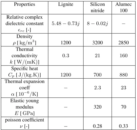
The electromagnetic, thermal and mechanical properties of the lignite (Romonta), Silicon nitride GP 79 (Friatec) and Aluminum Alumec 100 (Alcoa) were assumed constant and are given in the Tab.1(Properties expressed as a function of the temperature will rend the model non lin-ear, and do not bring much more information in the design phase of the applicator). Lignite is a semi mineral organic material consisting of Car-bon (73 %), oxygen (20 %), hydrogen (5 %) and nitrogen (1.2 %). Since the briquettes are made from brown coal powder, the material is homoge-neous and isotropic at a macroscopic scale and so the real and imaginary part of the complex permittivity are scalar number. For the simulation, the relative permittivity used isr = 5.48−0.73jand is obtained from the averaging of the dielectric measurements of fresh lignite briquettes (with water content) performed in our laboratory (see Fig.3). For the ceramic tube, a silicon nitride (GP 79, Friatech) was chosen because of a very high mechanical strength and low dielectric losses. For the aluminum block, the high strength aluminum Alumec 100 alloy was the best choice, be-cause of a good electrical and thermal conductivity together with a high mechanical strength. In addition, Aluminum alloys are materials easy to be machined.
5. MICROWAVE AND THERMAL MODEL
A standard waveguide WR 430 intersecting with the silicon nitride tube was modelled with Comsol 4.3 to compute theS11magnitude (|S11|dB=
10log(Pr
Pi), withPrandPithe reflected and incident power), the electric
fieldEand the power densityqdistribution by solving the wave equation
Properties Lignite Silicon Alumec nitride 100 Relative complex
dielectric constant 5.48−0.73j 8−0.02j −
rc[-] Density
ρ[kg/m3] 1200 3200 2850
Thermal
conductivity 0.3 21 160
k[W/(mK)] Specific heat
Cp[J/(kg.K)] 1200 700 880
Thermal expansion
coeff − 2.3 23
α[10−6/K] Elastic young
modulus − 320 70
E[GPa] poisson coefficient
ν[-] − 0.28 0.33
Table 1Dielectric, thermal and mechanical properties for the lignite coal, silicon nitride and Aluminum material used in the sequentially coupled model
Fig. 4 Electromagnetic model with boundary conditions, from the geom-etry and field symmgeom-etry, only one half is modelled
in the frequency domain at2.45 GHz:
1
µr
∇ ×(∇ ×E)−k20rcE= 0 (1)
k20=ω 2
µ00
rc=
0
r−j
00
r
q=1 2ω0
00
rE
2
withk0the wave number in free space,rcthe relative complex dielectric permittivity,ω = 2πfthe pulsation andqthe power density calculated from the electric field. Lignite is a non magnetic material so the rel-ative magnetic permeability isµr = 1. µ0 = 4π×10−7 H/mand 0 = 8.854×10⁻¹²F/mare respectively the permeability and
per-mittivity of free space. Using the symmetry of the applicator and of the fundamental modeT E10, only half of the applicator geometry was
conduc-tors. A scattering boundary condition was used on both surfaces where the lignite enters and exits the ceramic tube. The boundary conditions for the electromagnetic model are shown in Fig.4. With some quarter wave length matching elements inserted inside the wave guide, it was possi-ble to achieve a good transmission of the energy from the wave guide to the lignite briquettes. Later, during the applicator development process, the matching elements inserted inside the wave guide were removed and an external manual three pin tuner was used instead. In a second step, the power densityqobtained from the electromagnetic model was used to compute with the heat equation the temperature distribution inside the lignite material and the ceramic tube. The effect of the moving briquettes at constant velocityvinside the ceramic tube was included with the op-tion "translaop-tional moop-tion" in the Comsol thermal model. This effect is modelled by the transport termρCpv∇T shown in Eq.2. The temper-ature field in the lignite, and ceramic domain is obtained by solving the heat equation:
ρCp ∂T
∂t +ρCpv· ∇T =∇ ·(k∇T) +q (2)
withρ, Cpandkthe density, specific heat and thermal conductivity of the material.
6. THERMO-MECHANICAL MODEL
A thermo mechanical model was developed in order to compute the von Mises stress in the two critical parts of the applicator: the ceramic tube and the aluminum bloc. The ceramic is submitted to three source of me-chanical stress.
• The non uniform temperature distribution inside the ceramic wall leads to thermal stress.
• A graphite joint is used on both end face of the ceramic tube, with an axial stress of50 MPafor a good sealing,
• The internal pressure during the process can reach65 bars.
With a 3-D mechanical model, the total stress was computed with the thermal stress (due to the temperature gradient) and with two pressure boundary conditions on the inner wall of the ceramic and on both flat surfaces. The mechanical model is based on force equilibrium of solids (or Newton law extended to solids):
ρu¨(x, t)− ∇ ·σ(x, t)−κ(x, t) = 0 (3)
withρthe density of the solid,uthe displacement vector,σis the mate-rial stress tensor for small deformation. κis the external volume forces such as gravity. In our case, the gravity can be neglected in compari-son to the internal thermal stress. In addition, the inertial termρ¨uis neglected in comparison to the thermal stress because the time of the du-ration of the ”heat pulse” (microwave heating about1−3 s) is much larger than the characteristic time of propagation of stress waves inside the solid (speed of sound in the material over a characteristic length of the solid). The equation (3) without the inertial term is also called the quasi static approximation equilibrium of solids. The constitutive law between the stress and the strain used to model the behaviour of the ceramic and the metal parts is a linear elastic model or generalised 3D Hooke’s law:
σ= E
1 +ν+
Eν
(1 +ν) (1−2ν)tr()I (4)
−α E
1−2ν∆TI
Three parameters are used to define the relationship between the strain
and the stressσin the case of thermal expansion with a temperature dif-ference∆T. The Young modulusE, which represents the stiffness of the
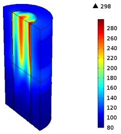
Fig. 5Power density [MW/m3] for10 kWinput power
material, the poisson ratioνwhich is the ratio between longitudinal and lateral displacement, and the linear thermal expansion coefficientα. The Von Mises stressσm = √1
2
p
(σ1−σ2)2+ (σ2−σ3)2+ (σ3−σ1)2,
is a convenient scalar quantity used to evaluate the stress state inside the solid and to compare with the maximal material strength.σiare the main stress components of the stress tensor.
7. THERMAL AND FLUID MODEL
The velocity field inside the water channels was computed with the lam-inar flow physics of Comsol (Navier stokes equation for an incompress-ible fluid in laminar regime) in steady state. Then, the thermal model was solved in the solid and in the fluid domain. To take into account the heat transfer from the solid domain to the fluid domain, the advection term
vρCp· ∇Tis used withvthe velocity field obtained with the steady lam-inar incompressible fluid simulation.
Comment: The author had also the opportunity to test the pipe flow mod-ule in Comsol. The calculated temperature field in the solid domain (alu-minum block) was similar for both cases, but the water channels are de-fined as lines and incorporate the analytic solution based on energy bal-ance for a laminar flow in a tube (poiseuille flow, parabolic profile). The computation time is much shorter than the fluid simulation with Navier Stokes equations.
8. SIMULATION RESULTS AND DISCUSSION
The figure5shows the power density distribution inside the lignite and ceramic tube. There are 3 maximum located in the ceramic and lignite material (one in front of the aperture of the wave guide at the interface ceramic/lignite, one in the center, and one at the interface ceramic/lignite on the opposite side of the wave guide aperture). A maximum power density of about100 MW/m3was achieved inside the lignite material.
Fig. 6Temperature [◦C] distribution after1 hof continuous running with a constant briquette translation velocity ofv= 2.5 cm/s, corre-sponding to75briquettes per minute
a) b)
Fig. 7Temperature after 1 h of continuous running with a water flow rate of 6 l/min in the aluminium block a) and in the midle plane of the block b)
temperature field inside the ceramic and metal block was computed for 6 l/minwater flow rate. The figure7shows the temperature distribu-tion inside the aluminum block (a)) after1 hof continuous running at 10 kWinput power and in the middle plane of the aluminium block b). The white domain in the Fig.7is the wave guide filled with air. The ce-ramic and lignite material have also be hided to see the temperature in this plane. For a flow rate of6 l/min, the maximum temperature inside the steel block is about44◦C in the aluminum block. For the same flow rate and input power, the maximal temperature calculated for a steel block is about120◦C . The non uniformity of the temperature distribution (or temperature gradients) is much higher for the steel block than the alu-minum block because of its lower thermal conductivity. This shows that thermal expansion can be mitigate by using and aluminum alloy together with a sufficient water flow. For this application, the use of Stainless steel is not recommended because of lower electrical and thermal conductivity than aluminum.
The maximum total Von Mises stress calculated with the thermo mechan-ical model (temperature field as an input) was about40−60 MPain the middle of the ceramic as shown in Fig.8a) (green and yellow range on the figure, the maximum is not physical since its correspond to a cor-ner singularity with fixed displacements). This stress value is well below the maximum tensile and compressive strength of the silicon nitride tube (more than400 MPafor the tensile strength and3000 MPafor the com-pressive strength). For certifications reasons, the ceramic cylinder was also tested with high pressure water at5times the nominal pressure, ie 325 bars.
A modified model with the full geometry was used to compute the stress and displacement distribution inside the aluminum block. This block ex-periences stress from the inhomogeneous temperature distribution and from the2×8M22 screws used to connect the applicator to the flange for
a) b)
Fig. 8Von Mises stress [MPa] in the ceramic Silicium nitride tube and inside the Aluminum block after1 hof continuous running. Ther-mal stress, internal pressure, pressure from the gasket and forces from the screws are included in this model, high stress at the 4 corners are due to the fixed displacement boundary condition. The scale is limited to60 MPa
a good sealing. After1 hof continuous running, the maximal value for the Von Mises stress in steady state conditions was about30−50 MPa in the vicinity of the screw thread insert (Fig. 8b)). This value was well below the maximum tensile strength of Alumec 100 which is about 500 MPa. The maximum displacement was below0.15 mmfor a force of60 kNper screw and flow rate of6 l/min.
Overall, these thermo mechanical simulations have shown a good design of the applicator with stress level well below the maximal strength of the materials. In addition, the cooling circuit is essential in order to limit the maximal temperature and consequently the thermal expansion of the block.
9. EXPERIMENTAL RESULTS
The initial tests were performed without the briquetting press machine and the ceramic cylinder was simply filled with liqnite briquettes. For these static conditions (no moving briquettes through the ceramic canal) few tests at a maximum power of4 kWand for a maximum time dura-tion of10 swere performed. The temperature field just after microwave treatment was measured with a thermo camera as shown in Fig.9. Surface temperature of about100◦Cwere measured.
a) b)
Fig. 9 Surface temperature obtained with a thermo camera, lateral and front view of 4 lignite briquette after microwave treatment, max temperature99◦C
Fig. 10Mean force [N] required to break the briquettes after microwave irradiation, for power ranging from0to10 kW
per minute. Cracks formation with surface and core temperature of the lignite briquettes higher than120◦Cwere measured.
A radial crack from the center to the outside was observed on all the microwave heated briquettes. Briquettes were heated at different power and were collected at the exit of the metallic tube (connected to the ap-plicator) to measure the core temperature with a thermo coupled, after drilling a hole in the center. After that, they were put in a compressive stress machine, to measure the force required to induce breakage. The temperature was obtained from averaging 3 temperature measurements with 3 briquettes with the same input power and speed operating con-ditions. The figure 10shows the force required to break the briquettes for different input power level together with the measured core temper-ature of the briquette (in red). It is interesting to see that even with a power of500 Wthe briquettes are significantly weakened (9 kNfor a briquette without microwave heating and6 kNfor a briquette heated with 500 W). The core temperature are all above100◦Cfor power ranging from6to10 kW. The temperature values should be taken cautiously be-cause many sources of uncertainty exist (time during manipulation, hole drilling, resident time of the briquette in the metallic tube). Overall the Fig.10shows that microwave heating significantly increase the friabil-ity of the lignite briquettes. It is believed that a combination of thermal stress and pore pressure from water vaporization is the cause of thermal cracking.
10. CONCLUSION
A compact10 kWmicrowave applicator for heating and thermal crack-ing of lignite briquettes was successfully designed and tested. With10 kW input power, this applicator allows the heating of wet lignite briquettes (water content in mass of about∼15%) with temperature above100− 120◦Cand with average briquettes velocities in the range1.6to2.5 cm/s. The utilization of a silicon nitride tube is the key of this high pressure ap-plicator because this material combines both a high mechanical strength and very low dielectric losses. In operation, the aluminum block incorpo-rating an efficient water cooling circuit remains below45◦Cas predicted by the thermal simulations.
The preliminary strength measurements have shown a significant mechanical weakening of the briquettes under microwave heating. In-ternal cracks are created during fast microwave heating, it is not clear yet what is the dominant phenomenon between pore pressure from water expansion/vaporization and thermal stress due to temperature gradients. Additional experimental tests and measurements are planned to study
fur-ther the lignite coal material behaviour under fast microwave heating. During the development phase of the applicator, the use of a se-quentially coupled model between the electromagnetic, thermo fluid and mechanical physics allows the design of a reliable applicator with the de-sired specifications. It gives some good indications about the physical behaviour of the applicator in operation.
Finally, this applicator could be used for other lossy materials in liquid, solid, powder or granular form for continuous volumetric heat-ing with internal pressure rangheat-ing from atmospheric pressure to65 bars. Applications in chemistry and recycling are foreseen.
ACKNOWLEDGEMENTS
The authors would like to thank Dr. Heiner Gutte, TU-Bergakademie Freiberg, for the founding within the DER-project FE-35025755 "Studie zur berührungslosen Erwärmung und Schwächung von Kohlebriketts mit Mikrowellen für die Feststoffvergasung".
NOMENCLATURE
ρ density (kg/m3)
Cp specific heat (J/kg·K)
k thermal conductivity(W/(m.K))
σ stress tensor (Pa)
strain tensor (Pa)
I identity tensor (Pa)
E Young modulus (Pa)
ν poisson ratio (-)
α linear expansion coefficient (1/K)
rc relative complex permittivity (-) µr relative permeability (-)
E Electric field vector (V/m)
ω pulsation (rad/s)
q power density (W/m3)
T Temperature (K)
v average velocity of the briquette (m/s)
n normal vector to a given surface (-)
H magnetic field(H/m)
0 permittivity of free space (F/m) µ0 permeability of free space(H/m)
∇ gradient operator ∇· divergent operator ∇× curl operator
REFERENCES
Batar, T., 2004, “Theory and Applications of Microwave Energy in Com-munition,”Euro Ceramics VIII, 1399–1402.
http://dx.doi.org/10.4028/www.scientific.net/KEM.264-268.1399.
Binner, E., Lester, E., Kingman, S., Dodds, C., Wu, J.R.T., Wardle, P., and Mathews, J., 2014, “A Review of Microwave Coal Processing,”Journal of Microwave Power and Electromagnetic Energy,48, 35–60.
Pickles, C., Gao, F., and S.Kelebek, 2014, “Microwave Drying of a Low Rank Sub Bitumous Coal,”Minerals Engineering,62, 31–42.
http://dx.doi.org/10.1016/j.mineng.2013.10.011.
Rosin, A., Schroder, H., and Repke, J., 2014, “Briquetting Press as Lock Free Continuous Feeding System for Pressurized gasifiers,” Fuel,116, 871–878.
![Fig. 5 Power density [ MW/m3] for 10 kW input power](https://thumb-us.123doks.com/thumbv2/123dok_us/8813538.1778992/4.612.359.532.55.239/fig-power-density-mw-m-kw-input-power.webp)
![Fig. 10 Mean force [N] required to break the briquettes after microwaveirradiation, for power ranging from 0 to 10 kW](https://thumb-us.123doks.com/thumbv2/123dok_us/8813538.1778992/6.612.36.298.55.204/mean-force-required-break-briquettes-microwaveirradiation-power-ranging.webp)
