THERMO-ECONOMIC ANALYSIS OF A HEAT RECOVERY STEAM
GENERATOR COMBINED CYCLE
O. O. Ighodaro
1, *and M. Osikhuemhe
1,2,
D
EPARTMENT OFM
ECHANICALE
NGINEERING,
U
NIVERSITY OFB
ENIN,
B
ENINC
ITY,
E
DOS
TATE.
NIGERIA
E-mail addresses:
1[email protected]
,
2[email protected]
ABSTRACT
A significant amount of energy gets lost through the exhaust of simple gas turbine plants, more often than not, this energy can be used to run another power cycle or a combined heat and power setup, leading to an increase in the overall efficiency of the plant, reduce air pollution and energy wastage. In this study, a retrofitted performance analysis of incorporating a steam power cycle to the existing gas turbine cycle in Delta IV power station is carried out, the analysis is carried out using first law of thermodynamics and energy cost comparison to describe the effect of combining both cycles on power output, thermal efficiency and energy cost. Operating data were obtained from existing gas thermal plant in Ughelli (Delta IV) and steam thermal plant in Lagos (Egbin). Preliminary assessment shows that power output increases by a further 51.5MW, thus raising the overall combined efficiency to 41.85%. Analysis on cost savings accruable from incorporating a heat recovery steam generation was also done and significant savings in cost was obtained.
Keywords: combined cycle, HSRG, gas turbine, steam turbine, energy cost,
1. INTRODUCTION
The worlds increasing population and rapid industrialization requires sustainable energy supply which is crucial for development. Climate concerns requires that clean, climate friendly and affordable energy technologies be deployed in harnessing it [1]. Growing concerns and challenges in the fossil fuel industry and due to recent advancements in energy sustainable systems, the combined cycle arrangement is attracting lots of research interest, as it is regarded as the most efficient energy conversion system in addition to significantly reducing emissions and energy wastage [2].
The combined cycle power plant is the arrangement of a gas turbine with a steam bottoming cycle, the basic principle entails powering the gas turbine by burning gas fuel by a coupled generator, the high temperature exhaust gas is recovered in a heat recovery steam generator (HRSG) which is then used to produce steam for the steam power cycle, which then produces additional power. Combined cycle plants are known to be more efficient than
conventional single generating plants with efficiencies as high as 60% in some cases [3]
The installation of heat recovery steam generator (HRSG) and steam power plant equipment to achieve a combined cycle configuration is a more attractive option since it does not require modification of the existing gas turbine and the construction of the steam power plant will not interfere with the operation of the turbine resulting in minimum plant downtime and loss in productive capacity.
A number of authors have researched on combined cycle arrangement and performance improvement options. Khan, et al [4] carried out thermodynamic analysis to investigate new advancements of high performance for combined cycle power plants, their study used parametric analysis to optimize the performance of the combined cycle arrangement which included a bypass valve, the result obtained showed a 45% gain in power output when the inlet temperature of the topping cycle increases from 1000K to 1400K, Lacopo, et al [4] also used thermodynamic analysis to investigate the most
Vol. 38, No. 2, April 2019, pp. 345 – 350 Copyright© Faculty of Engineering, University of Nigeria, Nsukka,
Print ISSN: 0331-8443, Electronic ISSN: 2467-8821
www.nijotech.com
efficient match for a vapour cycle bottoming cycle using the 2nd law of thermodynamics, results showed a 12% increase in efficiency of the vapour cycle. Bianchi, et al [5] and Zhu, et al [6] studied the possibility of using the waste heat from gas turbine plants to power a bottoming cycle, Macian, et al [7] went on to develop optimization options of bottoming cycle which can then be used in waste heat recovery systems in vehicles. Polyzakis, et al [8] carried out optimization of combined cycle reheat arrangement, results indicating that the reheated gas turbines are the most viable option. Xiang, et al [9] studied performance improvement and optimization of selected combined cycle power plants in china, the results obtained from the study shows that increasing the HRSG inlet temperature beyond 5900C does not significantly improve cycle efficiency and with HRSG optimization with the use of gas to gas heat recuperation increases the combined cycle efficiency to 59%.
The gas turbine exhaust, typically at a temperature of 500-600°C [10] is used to raise steam in the HRSG; this steam is then used in steam turbine to drive a generator. The turbine exhaust has unused oxygen content and it is possible to burn additional fuel in the boiler to raise steam output; this supplementary firing is most used with gas turbine operating at a relatively low exhaust gas temperature [11]. The exhaust from the HRSG may be used in processes such as paper drying, brewing, heating of building, sterilizing or for preheating combustion air for the furnace at a carbon baking facility, this is referred to as Cogeneration or combined Heat and Power (CHP). Zhang, et al [12] and Peris, et al [13] carried out studies on utilizing the waste heat from internal combustion engines, both papers show that power output improved marginally when heat recovery was incorporated.
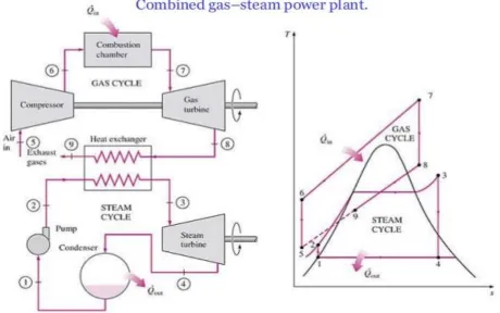
2. SYSTEM DESCRIPTION
The combined cycle arrangement is the combination of two cycle with the primary aim of improving work output and overall efficiency, the primary cycle, termed the topping cycle is the gas power cycle working on the principle of the Brayton cycle, its high-quality exhaust heat is used to run the second cycle, termed the bottoming cycle which in this case is the steam power cycle working on the principle of the Rankine cycle. The working fluid of the topping cycle is combustible gases while that of the bottoming cycle is steam. The gas turbine plant to be used for this
analysis is the Delta IV Power Station, Ughelli while the steam power plant used is the Egbin Power Station, Ikorodu.
In the gas turbine (topping) cycle, air at atmospheric pressure and temperature (p5, T5) enters the compressor, where it is compressed to higher pressure and temperature (p6, T6). This high pressure and temperature air enter the combustion chamber where fuel gas is added in the combustion process. After leaving the combustion chamber, the products of combustion at pressure and temperature (p6, T7) enters the turbine where it expands to the temperature T8. On leaving the turbine, the quality of the exhaust gases is still significantly high as well as the amount of energy in the gasses. Such gases if allowed to exhaust in to the environment (as currently the case in Delta IV), they will contribute to global warming.
In order to extract this energy and save the plant, a heat recovery steam generator (HRSG) is installed in the exhaust channel, after which the gases exhaust to the atmosphere at temperature T9. The HRSG acts as the combustion chamber for the bottoming cycle. In the bottoming (steam power) cycle, condensed feed water enters the pump at state 1 (p1) where it is pumped to higher pressure and temperature (p2, T2) before entering the HRSG where superheated steam is generated at (p3, T3), before entering the turbine where it is expanded to the condenser conditions of p4. Figure 1 shows the schematic of the proposed combined cycle arrangement and its corresponding T-s diagram.
Although the characteristics compactness of the gas turbine is sacrificed in binary cycle plants the efficiency is much higher than is obtainable with the simple cycle such that turbines are now widely used for large scale electricity generating stations [14]
3.1 Thermodynamic analysis of Gas Power Cycle (Delta IV)
In the gas turbine topping cycle, data used in computing the work output and thermal efficiency were obtained from the research work on Delta IV power station by Ighodaro [10]. Using the states in Figure 1, the turbine work (Wtg) in the gas power cycle is given by:
𝑊𝑡𝑔= 𝑚𝑔𝑐𝑝𝑔(𝑇7− 𝑇8) (1)
where
𝑇8 = 𝑇7{1 − 𝜂𝑡(1 − 𝑟𝑝 −𝛽
Figure 1: Schematic Diagram of Combined Gas & Steam Power Cycle
The compressor work (Wcg) in the gas power cycle is given by:
𝑊𝑐𝑔 = 𝑚𝑎𝑐𝑝𝑎(𝑇6− 𝑇5) (3)
where
𝑇6 = 𝑇5{1 +
(𝑟𝑝−𝛼− 1)
𝜂𝑐 } (4) The network output of the gas power plant (Wnetg) is given by:
𝑊𝑛𝑒𝑡𝑔= 𝑊𝑡𝑔− 𝑊𝑐𝑔 (5)
The heat supplied (Qg) in the combustion chamber of the gas turbine is given by:
𝑄𝑔= 𝑚𝑔𝑐𝑝𝑔𝑇7− 𝑚𝑎𝑐𝑝𝑎𝑇6 (6)
The energy efficiency of the gas turbine cycle is given by:
𝜂𝑔𝑐 = 𝑊𝑛𝑒𝑡𝑔 𝑄𝑔
(7)
3.2 Thermodynamic analysis of the HRSG A single pressure HRSG is installed to replace the boiler in the steam power plant. The HRSG is expected to reduce the exhaust gas temperature of the gas power cycle before it exhausts to the atmosphere while generating superheated steam for the steam power plant operation.
The heat recovered from the exhaust gases (Qr) is given by:
𝑄𝑟= 𝑚𝑒𝑥𝑐𝑝𝑒𝑥(𝑇8− 𝑇9) (8)
The portion of the recovered heat transferred in the HRSG which is used to generate steam is given by:
𝑄𝑠 = 𝜀𝑄𝑟 (9)
3.3 Thermodynamic analysis of Steam Power Cycle (Egbin)
In the steam turbine bottoming cycle, data used in computing the work output and thermal efficiency were obtained from the research work on Egbin power station by Ohenhen [15]. Using the states in Figure 1, the turbine work (Wts) in the steam power cycle is given by:
𝑊𝑡𝑠= 𝑚𝑠(ℎ3− ℎ4) (10)
The pump work (Wps) in the steam power cycle is given by:
𝑊𝑝𝑠= 𝑣𝑓(𝑝2− 𝑝1) (11)
The network output of the steam power plant (Wnets) is given by:
𝑊𝑛𝑒𝑡𝑠= 𝑊𝑡𝑠− 𝑊𝑝𝑠 (12)
The energy efficiency of the steam turbine cycle is given by:
𝜂𝑠𝑐= 𝑊𝑛𝑒𝑡𝑠 𝑄𝑠𝜂𝑚𝑒𝑐ℎ𝜂𝑔𝑒𝑛
3.4 Thermodynamic analysis of retrofitted combined cycle
The combined cycle is the combination of the gas turbine (topping) and steam turbine (bottoming) cycles as shown in Figure 1. The combination increases the network output of the cycle and the efficiency.
The network of the combined cycle (Wnetcc) is given by:
𝑊𝑛𝑒𝑡𝑐𝑐 = 𝑊𝑛𝑒𝑡𝑔+ 𝑊𝑛𝑒𝑡𝑠 (14)
The overall efficiency of the combined cycle is given by:
𝜂𝑜𝑐= 𝑊𝑛𝑒𝑡𝑐𝑐 𝑄𝑔
(15)
4. ENERGY COST ANALYSIS
The fuel or energy costs, Ec (mills/kWh) for natural gas fired power station is given by [14]:
𝐸𝑐=
𝐹𝑐(𝑑𝑜𝑙𝑙𝑎𝑟𝑘𝑊ℎ) × 100 (𝑑𝑜𝑙𝑙𝑎𝑟𝑠𝑚𝑖𝑙𝑙𝑠 )
𝜂𝑜𝑐𝑄𝑛𝑒𝑡(𝑘𝑊ℎ𝑘𝐽 ) × 𝑘𝑊ℎ/3600𝑘𝐽
=3.6 × 10
6𝐹
𝑐
𝜂𝑜𝑐𝑄𝑛𝑒𝑡 (16)
Where: 𝐹𝑐 = Fuel cost in Dollars/kWh; 𝑄𝑛𝑒𝑡= energy
release per unit fuel mass, kJ/kWh; 𝜂𝑜𝑐 = overall thermal efficiency; Mills/kWh = standard expression for cost of electricity (1mill/kWh = $1/MWh =N360/MWh)
Exchange rate as at July 2006: $1 = N150 (the period for which Power Station operation data is available)
5. RESULTS AND DISCUSSION
The network output of the power stations when operating individually and when combined in a combined cycle set up is shown in Figure 2.
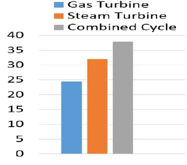
The Thermal efficiencies of the power stations when operating individually and when combined in a combined cycle set up is shown in Figure 3.
As seen from Figure 2, the installation of a combined cycle arrangement instead of the existing individual gas and steam power plants creates a considerable increase in power output from the individual 89.9MW and 53.6MW for the gas and steam plants respectively to the 143.5MW for the combined cycle, also from Figure 3 the same appreciable gain in thermal efficiency is noticed from the 24.4% for the gas turbine cycle to the 37.9% for the combined cycle power plant.
A further comparison of Figure 2 and 3, shows that although the power output of the steam cycle is less than that of the gas cycle, the efficiency of the steam is much higher than that of the gas, this is due to the far less heat supplied in the steam cycle due to the
presence of air preheaters and economizers in the boiler pathway in the steam turbine.
The considerable gain in power output and thermal efficiency noticed in Figures 2 and 3 makes the combined cycle plant suitable for base load power generation due to reduced cost of generation. To avoid having one steam turbine train for each gas turbine unit, it is more economical to have two gas turbines and HRSG to drive one steam turbine train as used in the design of the AGIP power installation in Kwale, Delta State. In such instance, the power output from the steam power output from the steam turbine generator terminal would be greatly increased.
Figure 2: Network output of Power Stations
Figure 3: Thermal Efficiencies of Power Stations
5.1 Energy cost analysis for gas turbine plant when used as base load carrier
Using GT 15 as a case study for the period from January 2004-March 2005:
Amount of fuel supplied = 11,872,952mcf Cost of unit of fuel in Naira = N0.2159/kWh Net energy release per unit of fuel:
1030𝐵𝑡𝑢
𝑐𝑓 × 1.054 × 10³ 𝐵𝑡𝑢 ×
𝑘𝐽
1000𝐽= 1085.6kJ/cf =
3.61 ×10³kJ/kWh
Using Equation 16:
𝐸𝑐 =
3.6 × 10⁶𝐹𝑐
𝜂𝑜𝑄𝑛𝑒𝑡
= 3.6 × 10
6× 0.2159
0.244 × 3.61 × 103
= 882.4 𝑚𝑖𝑙𝑙𝑠/𝑘𝑊ℎ
Total cost of fuel for GT 15 = N882.4 × 907504 = N800.8 Million
Assume all five GTs are working as Gt 15, total energy generated by station;907 504 × 6 = 5 445 024MWh Total cost of fuel for GTs in station: 882.4 × 5 445 024 = N4.8 billion
5.2 Energy cost analysis when gas turbine plant is incorporated in the combined cycle arrangement
Total energy generated =1 308 752 MWh Overall thermal efficiency at full load = 37.4% Fuel cost = N65/mcf
Amount of fuel supplied = 11872.952 mcf Cost of unit of fuel = N0.2159/kWh Net energy released per unit fuel
1030𝐵𝑡𝑢
𝑐𝑓 × 1.054 × 10³ 𝐵𝑡𝑢 ×
𝑘𝐽
1000𝐽= 1085.6kJ/cf =
3.61 ×10³kJ/kWh
Using the earlier developed equation: Ec = 3.6 ×10⁶𝐹𝑐
𝜂𝑜𝑄𝑛𝑒𝑡 =
3.6 × 106× 0.2159
0.374 × 3.61 × 103 = 575.7mills/kWh
Total cost of fuel for GT 15 = N575.7 × 1308725 = N735.4 million
Assume all five GTs are working as GT 15, total energy generated by station:
1308725 × 6 = 7 852 350 MWh
Total cost of fuel for GTs in station: 575.7 × 7852350 = N4.52 billion
5.3 Saving in Fuel Cost by Using A Combined Cycle
Saving in cost of fuel per GT = N800.8 million - N735.3million = N47.5million
Savings in cost of fuel for station = N4.8 billion - N4.52 billion = N280 million
As seen from the above hypothetical combined cycle scheme a considerable increase in power output production is achieved at a much higher efficiency, the use of supplementary firing would increase cost of fueling but gives much higher output from the steam
turbine generator terminal, then the advantage of a further increase in output to be gained from combined cycle arrangement would have to be weighed against the increased cost of fueling.
6. CONCLUSION
A thermodynamic analysis for incorporating a steam turbine plant and a gas turbine plant in a combined cycle arrangement using a heat recovery steam generator has been explored and a performance evaluation and cost analysis has been efficiently applied. The results improve the understanding of such combined cycle behaviors, revealing that the combined cycle plant provides a much higher load output, significant improvement in efficiency, and even though there is a greater complexity in the plant and a higher cost of equipment, there is considerable reduction in the fuel cost.
The possibility of incorporating a steam turbine unit to utilize the high exhaust gas from the gas turbine unit (combined cycle) was studied: the findings reveal a much higher load output, improved efficiency and reduced fuel cost.
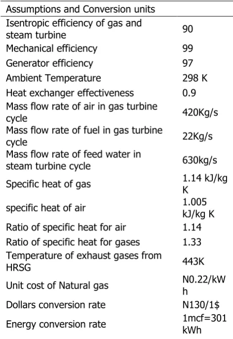
Table 1: Major Assumptions and Conversion Units.
Assumptions and Conversion units Isentropic efficiency of gas and
steam turbine 90
Mechanical efficiency 99 Generator efficiency 97 Ambient Temperature 298 K Heat exchanger effectiveness 0.9 Mass flow rate of air in gas turbine
cycle 420Kg/s
Mass flow rate of fuel in gas turbine
cycle 22Kg/s
Mass flow rate of feed water in
steam turbine cycle 630kg/s Specific heat of gas 1.14 kJ/kg K
specific heat of air 1.005 kJ/kg K Ratio of specific heat for air 1.14 Ratio of specific heat for gases 1.33 Temperature of exhaust gases from
HRSG 443K
Unit cost of Natural gas N0.22/kWh
7. REFERENCES
[1] Khan M.N, Tlili I; New Advancement of High Performance for a Combined Cycle Power Plant: Thermodynamic Analysis, Case Studies in Thermal Engineering 12, 2018 pp 166-175.
[2] Ehsan Noorollahi, Dawud Fadai, Seved Hassan Ghodsipour, Mohsen Akbarpur Shirazi; A new optimization framework for power generation expansion planning with the inclusion of renewable energy-a case study of Iran, J. Renew. Sustain. Energy, 9, 2017, pp 15-30.
[3] Alessandro Franco, Claudio Casarosa; On some perspective for increasing the efficiency of combined cycle power plants, Applied Thermal Engineering 22(13), 2002, pp 1501-1518. [4] Lacopo Vaja, Agostino Gambaro; Internal
combustion engine (ICE) bottoming with organic rankine cycle (ORCs), Energy 35, 2010, pp 1084-1093.
[5] M. Bianchi, A De Pascale; Bottoming cycles for electric energy generation parametric investigation of available and innovative solutions for the exploitation of low and medium temperature heat sources, Appl. Energy, 88, 2011, pp 1500-1509.
[6] Sipeng Zhu, Kangyao Deng, Shuan Qu; Energy and exergy analysis of a bottoming rankine cycle for engine exhaust heat recovery, Energy, 58, 2013, pp 448-457.
[7] V. Macian, J.R Serrano, V. Dolz, J. Sanchez; Methodology to design a bottoming Rankine cycle, as a waste energy recovering system in vehicles. Study in a HDD engine. Appl. Energy, 104, 2013, pp 758-771.
[8] A.L Polyzakis, C. Koroneos, G. Xydis; Optimum gas turbine cycle for combined cycle power plant,
Energy Convers. Manag., 49, 2008, pp. 551-563.
[9] Wenguo Xiang, Yingying Chen; Performance improvement of combined cycle power plant based on the optimization of the bottom cycle and heat recuperation, J. Therm. Sci., 16 (1), 2007, pp 84-89 .
[10] Ighodaro O. O.; Performance Appraisal of Delta IV Power Station Ughelli, M.Eng Thesis. Thermal Power Engineering, University of Benin, 2006.
[11] I. H. Njoku, C.O.C Oko, J.C. Ofodu; Performance evaluation of a combined cycle power plant integrated with organic Rankine cycle and absorption refrigeration system; J. of Cogent Engineering 5, 2018, 1451426
[12] H.G Zhang, E.H. Wang, B.Y. Fan; A performance analysis of a novel system of a dual loop bottoming organic Rankine cycle (ORC) with a light-duty diesel engine, Appl. Energy, 102, 2013, pp 504-1513.
[13] Bernardo Peris, Joaquin Navarro-Esbri, Francisco Moles; Bottoming organic Rankine cycle configurations to increase internal combustion engine power output from cooling water waste heat recovery, Appl. Therm. Eng., 61, 2013, pp. 364-371.
[14] Weismann J and Eckert R; Modern Power Plant, Textbook, 1995, UK: Prentice Hall.
[15] Ohenhen A. G.: Turbine Inspection and Testing (A case Study Of Lagos Thermal Power Station Egbin, Lagos) (M.Eng Project), University Of Benin, 1998.