Directional Beamforming for Future Networks
Kelvin Anoh
†, Bamidele Adebisi
‡, Sumaila Mahama
§, Andy Gibson
‡and Haris Gacanin
¶ †University of Bolton, Deane Road, Bolton BL3 5AB, United Kingdom
‡
Manchester Metropolitan University, Manchester M1 5GD, United Kingdom
§The University of York, Heslington, York YO10 5DD, United Kingdom
¶
Nokia-Bell Labs, Antwerp, Belgium.
[email protected], {b.adebisi,a.gibson}@mmu.ac.uk, [email protected], [email protected]
Abstract—As the evolving communication standards would leverage on high data rates and low power consumption, future communication systems must be able to demonstrate these strengths. Space-time block codes (STBC) and quasi-orthogonal STBC (QO-STBC) including beamforming are multiple-input multiple output (MIMO) system design techniques used to improve data rates and reduce bit error ratio (BER). STBCs for larger antenna configurations use QO-STBC schemes which suffer from self-interference problems. The self-interference in QO-STBC systems diminishes the data rates and worsen the BER. In this study, we present three (3) methods of overcoming the self-interference problems in QO-STBC systems. We implement the interference-free QO-STBC systems with directional beamforming to improve the data rates and also reduce the BER. The results show significantly improved BER performance when the interferences are eliminated. An additional 3dB gain is achieved at 10−4 BER when the interference-free QO-STBCs are operated with directional beamforming. In terms of data rates, up to 6 bits/s at reasonably low power consumption are realized when the Hadamard-based QO-STBC is operated with directional beamforming.
Index Terms—BER, directional beamforming, MIMO, QO-STBC, STBC, SVD.
I. INTRODUCTION
The need for higher data rates at user-equipment (UE) is driving innovations on developing modern wireless communication systems to satiate such need. This is connected to the fact that majority of user applications used in running daily routines are increasingly becoming very mobile. These include banking, video, location, gaming, music and healthcare apps including apps for managing home utilities using the evolving internet of thing (IoT) technologies. In future networks (e.g. 5G, 5G-and-Beyond (5GB) and 6G), the wireless systems must simultaneously deliver high reliability, low latency, and high data rates across uplink and downlink to successfully operate IoT services [1], [2]. On top of these, the technology must be able to operate at reasonably low energy consumption as the UE is usually powered by finitely-limited battery capacity. High data rates and low power consumption are two disjoint design requirements that may be achieved at some levels of trade-offs.
This research work was supported, in part, by the Peer-to-Peer Energy Trading and Sharing - 3M (Multi-times, Multi-scales, Multi-qualities) project funded by EPSRC (EP/N03466X/1) and in part, by "Triangulum" project (part of H2020 Smart Cities and Communities programme) funded by the European Commission under Grant 646578-Triangulum-H2020-2014-2015/H2020-SCC-2014.
Starting with the increasing demands for higher data rates in future networks, different technologies (e.g. multiple-input multiple output (MIMO) and beamforming) are being studied [1], [2]. Combining MIMO and beamforming offer higher data rates. Beyond the conventional beamforming schemes, data rates at the receiver can be improved through directional and multi-directional beamforming schemes [3], [4], a good candidate for millimeter wave (mmWave) MIMO systems in the forthcoming 5G network [5]. Space-time block codes (STBC) [6] are MIMO design techniques with the potential of increasing received data rate and reducing the bit error ratio (BER) especially when operated with beamforming.
Beamforming with STBC [3] and quasi-orthogonal STBC (QO-STBC) [7] have been explored in the literature, however, there are no studies investigating beamforming on interference-free QO-STBC systems. As its name suggests, QO-STBCs have non-orthogonal matrices and enable only quasi (i.e. partial)-orthogonal matrices and makes it difficult to decouple transmitted signals at the receiver. This increases the receiver complexity. A way of overcoming this complexity is by forming an equivalent virtual channel matrix (EVCM) which enables linear detection at the receiver. The EVCMs for standard QO-STBC systems have off-diagonal terms that diminish the received BER. Different methods of removing the off-diagonal (interference) terms for n ≥ 3 transmit antennas include using Givens-rotation, Eigenvectors and Hamadamard matrices as modal matrices [8]–[10]. Hadamard modal matrices are particularly interesting because there are no zero-entries in the matrices thus increasing the channel gains and further reducing the peak-to-average power ratio (PAPR) of the system [9]. In this study, we will show that singular value decomposition (SVD) of the EVCM is also a suitable method of overcoming the self-interference problem.
order to reduce the BER and also increase data rates. The remaining parts of this study are organized as follows. The system model is presented in Section II wherein we introduced and derived the directional and the multi-directional beamformers for QO-STBC systems. Afterwards, we present the simulation results and discussions with the conclusion following in Section IV.
II. SYSTEMMODEL
The study of the substructures of STBC and QO-STBC channel matrices for precoding transmit symbols for optimum performance has been going on for sometime [3], [4], [11]. However, there are no efforts applying interference-free QO-STBC with directional and multi-directional beamforming schemes to optimize the existing standards. In this study, these problems are solved. Consequently, we harness this understanding to present multi-directional received signals in order to increase the received signal throughput and reduce the BER. Throughout this study, we assume that channel state information is present both at the transmitter and receiver.
A. Standard STBC and Detection Method
We start by considering an n= 2transmit antenna system equipped with m ≥ 1 receiving antennas. When m = 1, the discussion is limited to one receiver antenna system (or MISO). On the other hand, when m ≥ 2, the discussion expounds systems operating with multiple receiving antenna systems thereby qualifying for MIMO systems. Consider the standard STBC signals [6] which can be expressed as
X=
x1 x2
−x∗2 x∗1
(1)
transmitted over h1 and h2 uncorrelated channels, where x∗1 andx∗2are the complex conjugates ofx1andx2input signals, respectively. At the receiver (in the case of m= 1), we can express the received signals as
Y=
x1 x2
−x∗2 x∗1 h1 h2
+
z1 z2
=
h1x1+h2x2 h2x∗2−h1x∗2
+
z1 z2
(2)
wherez1 andz2 are additive white Gaussian noise respective to antennas 1 and 2; z1, z2 ∼ CN(0, σzj2), j = 1,· · ·, m. By taking the conjugate of the second row of (2), we observe that
Y∗=
h1x1+h2x2 h∗2x2−h∗1x2
+
z1 z∗2
=
h1 h2 h∗2 −h∗1
x1 x2
+
z1 z2∗
(3a)
=Hx+z (3b)
where x = [x1, x2]T and z = [z1, z2∗]
T. Note that [·]T
represents the transpose of [·]. In this study, special attention is given toH, which is usually referred to as equivalent virtual channel matrix (EVCM) [12] and can be expressed as
H=
h1 h2 h∗2 −h∗1
. (4)
Since it is usually difficult to decouple the transmitted signals x given in (1) at the receiver, forming an EVCM is veritable. The EVCM is usually important in designing STBC transceivers with linear detection at the receiver. Our interest is drawn to the properties ofHto improve on the performance of the STBC system. For example, sinceHis orthogonal, the detection of transmitted signals in the conventional standard STBC system is achieved by performing a linear multiplication of the received signal as follows
ˆ
x=HHY∗=HHHx+ ¯z= ˜x+HHz (5)
where˜x=HHHxandz¯=HHz. We note thatHHHis the channel detection matrix which can be represented as
HHH=
h2
1+h22 0 0 h2
1+h22
, (6)
where{·}H represents the Hermitian transpose of {·}. Since there are no off-diagonal terms in the detection matrix in (6), the STBC system with n= 2 is said to be interference-free. This approach easily overcomes the complexity in decoupling the transmitted signals using a simple linear operation. Another approach to realizing similar results is by using SVD. For example, by using SVD we can decompose the EVCM as
H=UDVH (7)
whereU∈Cn×nandV∈Cn×nare the eigenvectors; bothV
andUare unitary matrices. In other words,UHU≈VHV=
In, where In is the identity matrix of size n. Note also that D represents the eigenvalues, with diagonal entries d= [d1,· · ·, dn]which are positive definitive. It can be shown that
Dis equivalent toHHH. In other words, the optimal channel gains d2
i,1,···,k= arg max (DHD)≈arg max (HHH), which in turn represents the strongest signal beam in the system; where d2
1 ≈ d22 ≈ (h21 +h22). For example, by performing simple linear detection (in terms of SVD method) we find that
HHH=DHD=
d2
1 0
0 d2 2
. (8)
Thus, to implement the standard STBC system, the input signal is precoded withVand then at the receiver, the signal recovered by U, as in [13]. This scheme is also similarly applied in beamforming.
B. Transceiver Beamforming with STBC
Since the SVD approach maximizes signal power, we can exploit this to maximize received signal strength at the receiver, for example by using the concept of directional beamforming [3], [4], [7], [14]. For example, let the transmit signal be precoded before transmission as shown in [13] at the transmitter so that the resulting signal be expressed as follows
¯
C=¯
C1,· · ·,C¯n T
(9)
whereC¯i∈witxandwti ∈V,∀i= 1,· · ·, n. We refer towit as the beamformer at the transmitter. At the receiver, we have
wherewt∈Cn×n. We can recover the transmitted signals by
using a receiver beamformer as follows
ˆ
y=wHrH(wtx) + ˆz=wHrHwtx+wHrz, (11)
where ˆz = wHrz. To find the received signal to noise ratio (SNR) whenn= 2, then we write
γ2=E
{kwHrH(wtx)k2}
E{kwHrzk2}
=E{kw H
rHwtk2}E{kxk2}
wH
rE{kzk2}wr
=E{kw H
rHwtk2}
wH
rwr
Es σ2 z
=E{kwHrHwtk2}γ0 (12)
where E{·} is the expected value of {·}, σ2z = zHz and γ0 =Es/σ2z. For optimum performance, wt must be chosen to maximize γ2, such that kwtk2≤P whereP is a limiting transmit power level. By substituting the SVD from (7) into (12) forH, we find that
γ2=kwHrUDVHwtk2γ0=kw˜HrDwt˜ k2γ0 (13)
wherewt˜ =Vwtandwr˜ =wHrU. On this note, our goal is to choosewrandwtthat jointly maximizes the received SNR in (12). These optimal vectors that maximize (12) are known as the optimal beamformers. It has been shown in [15], [16] that the optimal transmit beamforming vector is woptt =
√
Pv1 and the corresponding optimal receiver beamforming vector is woptr = u1. Based on this, substituting accordingly in (11), we find that
ˆ
y= (woptr )HH(woptt x) + (woptr )Hz
=uH1UDV√Pv1x+uH1z. (14)
The result in (14) shows that the received signal at the receiver for a MISO system operating the STBC gives the strongest beam in joint transmitter-receiver beamforming. In other words, the STBC gives result equivalent to 1-directional beam. This is called the strongest eigenmode beamforming (SEB). However, it has been shown in [3], [4] that signals beams from the ’other’ directions can be exploited to increase the received signal throughput and thereby reducing the received BER; this is the concept of multi-directional beamforming. Thus, we modify (14) to include other beams as follows
ˆ
y=
k
X
i=1
uHi UDV√Pvix+uHi z (15)
where k = |ui| is the cardinality realized from solving the following optimization problem
wopti =arg max
wi=1,···,k
kw¯Hi D
√
Pwik
subject to:wi≤P. (16)
Notice that |ui, i= 1,· · ·, k|represents the cardinality of set
{ui}. Note thatwi¯ =uHi Uandwi=Vvi. The diversity gain realized from (15) can be immediately shown to be canonically greater than that of (14) .
C. Multi-Directional Beamforming with QO-STBC
The disadvantage of the standard STBC scheme is that the number of transmitting elements is limited to n= 2. Beyond this, the codes lose their orthogonality. To achieve n > 2 antenna configuration afterwards, STBC codes are combined to implement higher order antenna configurations, and these are referred to as QO-STBC codes. As the name implies, QO-STBC are not orthogonal and there are interfering terms in the detection matrices [12]. We will use the convention of Section II-A in discussing EVCM from QO-STBC codes. For example, supposing that there are four transmitting elements
h = [h1,· · ·, h4]T with x4 = [x1,· · ·, x4] to be sent over them, we realize the EVCM from the QO-STBC withn= 4 as described in [8], [9] from the received signals which can be expressed as
Y4=
x1 x2 x3 x4
−x∗2 x∗1 −x∗4 x∗3 x3 x4 x1 x2
−x∗4 x∗3 −x∗2 x∗1
h1 h2 h3 h4 + z1 z2 z3 z4 =
h1x1+h2x2+h3x3+h4x4 h2x∗1−h1x∗2+h4x∗3−h3x∗4 h3x1+h4x2+h1x3+h2x4 +h4x∗1−h3x∗2+h2x∗3−h1x∗4
+ z1 z2 z3 z4 . (17)
From (17), it is impossible to decode the transmitted signal via a linear operation at the receiver; this expands the complexity and power consumption of the receiver. To overcome these problems and decouple the transmitted signals by linear detection, we take the conjugates of rows 2 and 4 in (17), and find that
Y∗4=
h1x1+h2x2+h3x3+h4x4 h∗2x1−h∗1x2+h∗4x3−h∗3x4 h3x1+h4x2+h1x3+h2x4 h∗
4x1−h∗3x2+h∗2x3−h∗1x4
+ z1 z∗2 z3 z∗ 4 (18)
Y∗4=
h1 h2 h3 h4 h∗2 −h∗1 h∗4 −h∗3 h3 h4 h1 h2 h∗4 −h∗3 h∗2 −h∗1
x1 x2 x3 x4 + z1 z∗2 z3 z∗4
(19)
=H4x4+z4. (20)
wherez4= [z1,· · ·, z4]T and the EVCM for QO-STBC with n= 4 antenna elements becomes
H4=
h1 h2 h3 h4 h∗2 −h∗1 h∗4 −h∗3 h3 h4 h1 h2 h∗4 −h∗3 h∗2 −h∗1
. (21)
Unlike the case of n = 2 transmitting elements, we remark thatHHnHn6=diIn, i= 1,· · ·, nin (21), wheredi is channel gains. In other words, Hn is not an orthogonal matrix for n >2, e.g.n= 4. This is due to some off-diagonal elements in the detection matrix of (21), i.e. HH
order antenna configurations. For example, the n= 4 EVCM can be formed from the n= 2 EVCM thus
H4=
H12 H34
H34 H12
,H12=
h1 h2 h∗2 −h∗1
,H34=
h3 h4 h∗4 −h∗3
.
(22)
Similarly, for n= 8and so on, the EVCM can be formed as
H8=
H4 H58
H58 H4
(23)
where H58 forms the EVCM for antennas5,· · ·,8 as in the case of H4.
Definition 1 [17]:In the principle of matrix diagonalization, a given matrix, for exampleHn, can be converted to a spectral
matrix, Sn, by finding the modal matrices, Mn, followed by
M−n1HnMn=Sn operation.
We refer to Sn as the interference-free matrix. Standard examples of modal matrices that enable the realization of spectral matrices have been presented in [8], [11].
Definition 2 [8]: Given a matrix,Hn, the diagonal matrix,
Dn, can be formed by finding the eigenvectors [ei, i = 1,· · ·, n] such that HnEn = EnDn; En is the eigenvector
matrix with [ei, i= 1,· · ·, n] columnwise vector entries. Hence, to achieve interference-free detection matrix from the foregoing discussion, we adopt the modal matrices derived from Hadamard matrices [10], [18] because they do not have zero-entries like the ones in [12] which worsens the PAPR of the system [9]. In this case, we realize the interference-free detection matrix from performing
¯
Hn =HnMn (24)
where Mn represents then-th order Hadamard matrix (e.g., n= 4). In other words, the transmit symbol is first precoded using Mn before transmitting over the channel. It follows that the resulting interference-free detection matrix can be expressed as
¯
HHnH¯n=MHnH H
nHnMn
=diIn ∀i= 1,· · ·, n. (25)
Note that the right-hand side, (diIn), is also a spectral matrix (see [17]). Meanwhile, by using the SVD scheme again, which can be reaized as follows
¯
Hn = ¯UnD¯nV¯n, (26)
we can overcome these complexities with the potential of increasing the system performance. Then similar to transceiver beamforming in STBC codes, we can as well extend our attention to multi-directional beamforming in QO-STBC codes. For example, recall the EVCM realized in (21), we can express the received signal due to multi-directional beamforming as
ˆ
y=
k
X
i=1
uHi UnDnVn
√
Pvix+uHi z (27)
where k = 2 in (27) when n = 4. Note that ui and
vi,∀i = 1,· · ·, k are drawn from the optimal beamformer vectors. From the result in (27), it can be said that there are
k-direction beamforming realized from the scheme which can significantly improve the received SNR and consequently, the BER. Meanwhile, due to the non-zero entries in the modal matrices when the EVCM is operated with Hadamard-based modal matrices, the BER performance can be improved [9].
We can discuss the received SNR following as in Section II-A. For example, let the received SNR be expressed as
γn= k
X
i=1
|uHi UnDnVn
√
Pvix
|2
|uH
i z|2
= k
X
i=1
|uHi UnDnVn
√
Pvi
|2E
s
uH
i |z|2ui
= k
X
i=1
diag(Dn)2P Es σ2
z
= k
X
i=1
d2i,nP γ0 (28)
where γ0 = Es/σz2. As in the case of n = 2, we compare the SNR results realized from the conventional detection matrices of diagonalized QO-STBC system in (25) and that of multi-directional beamforming with QO-STBC in (28), it can be observed that the multi-directional beamforming scheme offers additionalk−1gains compared to the standard one-directional beamforming and also better than the standard QO-STBC with diagonalized detection matrices.
However, for the case of the diagonalized matrix (24), we can as well compute the SVD. Consequently, the received SNR can be expressed as
¯ γn=
k
X
i=1 ¯ d2
i,nP
σ2 n
(29)
where d¯n = diag( ¯Dn). For higher order antenna configurations (for example, n >4), similar conventions can be followed to realize and analyze the received SNR and consequently the BER performances. However, for antenna configurations outside the multiples of 4 (for example, n = 3,5,6,7,9, etc.), the corresponding EVCMs can be realized by ignoring one or more columns in the EVCM of nearest multiple of4to achieve the desired configuration as in [9].
For different antenna configurations, for example n ≥ 2, we assess the capacity performances. Assuming Gaussian signaling, the achievable rate can be expressed as
Rs= k
X
i=1 log2
Im+
|uHi UnDnVn
√
Pvix
|2
|uH
i z|2
.
(30)
We will assess the received data rates at the receiver for varying numbers of antenna configurations for low, fairly large and large multiple input antenna configurations.
III. SIMULATIONRESULTS ANDDISCUSSIONS
antennas such that the EVCM channel with elements as shown in (4) is realized which enables simple linear decoding at the receiver. Input signals normalized (with Es = 1) is then generated, digitally modulated using 16-QAM and then transmitted over then= 2transmitting channels and decoded using the STBC detection matrix shown in (6) which easily decouples the transmitted signals. Afterwards, the received signals are digitally demodulated and the recovered signals counted for errors. These steps are later repeated for SVD technique to compare/confirm our analytical derivation of the relationship between the eigenvalues of SVD-based EVCM and the direct orthogonality computation and the BER results are shown in Fig. 1. The BER results in Fig. 1 confirm that the SVD-based and EVCM-based detection matrices are equivalent. On the other hand, due to the Hadamard precoding of the channel matrix, it can be observed that BER is 3dB better at 10−4 BER than the SVD and Eig-based schemes.
A. BER results of STBC with Directional beamforming
In Fig. 2 the following BER results demonstrate the performances of the proposed system models in the foregoing discussion for QO-STBC system. The results are shown for BER performances of 16-QAM in the case of QO-STBC considering the different modal matrices present in the foregoing discussions. Standard STBC are different from the QO-STBC because they (STBCs) have orthogonal detection matrices, however, the EVCM of QO-STBC are usually made to achieve diagonalization so as to eliminate the self-interference terms. For the QO-STBC, this was achieved by processing the EVCM with different modal matrices described above. The BER results for the QO-STBC system are, respectively compared for SVD, eigenvectors (denoted as Eig) and Hadamard (denoted as Had) -based modal matrices. In all cases, the performances of QO-STBC operated with Hadamard-based modal matrices outperform all others as shown in Fig. 2. The results of BER performance of standard QO-STBC shows the impact of the detection matrix when the EVCM is not diagonalized. For example, it can be observed in Fig. 2 that the BER of the standard QO-STBC scheme is irreducibly poorer than all other schemes. Notice also that the 1-directional (eigenvector-based) modal matrix performed similarly as the SVD-based modal matrices because they share similar eigenvectors and eigenvalues.
B. BER Results of STBC with Multi-Directional beamforming
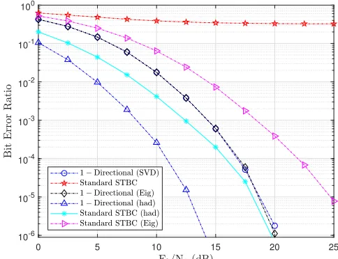
Here, the BER results of QO-STBC schemes operated with multi-directional beamforming are presented for QO-STBC systems operating with n = 4 transmit antennas and m = 1 receivers. First, comparing the 1-directional beamforming with the multi-directional beamforming scheme for (Eig), it can be see in Fig. 3 that the mult-directional beamforming outperformed the 1-directional beamforming scheme by 2dB gain at 10−4 BER. Furthermore, considering the case of Hadamard-based modal matrix, it can be seen that k multi-directional beamforming QO-STBC outperforms the 1-directional beamforming scheme by 3dB. Observe that in all cases, the Hadamard-based scheme outperforms
0 5 10 15 20 25 30
10-5 10-4 10-3 10-2 10-1 100
Figure 1: BER performances of standard STBC, SVD-based detection with one-directional beamforming (16-QAM, n = 2, m= 1)
0 5 10 15 20 25
10-6 10-5 10-4 10-3 10-2 10-1 100
Figure 2: BER performances of standard QO-STBC, SVD-based detection and one-directional beamforming (16-QAM, n= 4, m= 1)
all other QO-STBC schemes. In fact, the 1-directional Hadamard-based beamforming model outperforms the k directional beamforming scheme of the Eig-based modal matrices by∼3 dB at10−3 BER. In general, it can be seen that the multi-directional beamforming technique outperforms the conventional one-directional beamforming scheme for all the QO-STBC systems. In all cases, the QO-STBC systems operated with Hadamard-based modal matrices outperformed all others as hsown in Fig. 3.
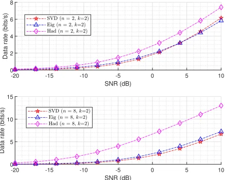
C. Results for data rate for multi-directional beamforming
-10 -5 0 5 10 15 20 10-5
10-4 10-3 10-2 10-1 100
Figure 3: BER results QO-STBC with multi-directional beamforming for different modal matrices (n= 4, m= 1)
-20 -15 -10 -5 0 5 10
SNR (dB)
0 2 4 6 8
Data rate (bits/s)
-20 -15 -10 -5 0 5 10
SNR (dB)
0 5 10 15
Data rate (bits/s)
Figure 4: Data rates for QO-STBC with different modal matrices and multi-directional beamforming
the Eig-based modal matrices and SVD-based modal matrices achieve nearly similarly performance when n = 2, however, the QO-STBC with Eig-based scheme achieves slightly higher data rate due to the eigenvalues and eigenvectors more than the SVD scheme for higher order configuration (e.g. n= 8). In all cases, there exists no zero entries in the Hadamard modal matrices thus offering richer channel gains and therefore higher data rate. With the multi-directional beamforming, the Hadmadard-based QO-STBC achieves 1.8 bits/s and 6 bits/s, respectively at 10dB SNR more than other schemes.
IV. CONCLUSION
In this study, we presented multi-directional beamforming for interference-free space-time block codes for low and fairly large number of transmitting antenna configurations for future communication systems. We derived optimal transceiver
beamformer and the SNRs metrics for the models. We showed the methods of improving the received signal throughput via multi-directional beamforming at both the transmitter and the receiver sides. The results we obtained showed that SVD technique is elegant for designing STBC systems with simplified receiver design. We derived and showed that with sufficient modal matrices, the SNR and BER performances of the STBC and QO-STBC systems can be improved when the channel matrices are processed with Hadamard-based modal matrices. When operated with beamforming, the results showed additional enhancement in the received SNR and in the reduction of the received BER at the receiver.
REFERENCES
[1] W. Saad, M. Bennis, and M. Chen, “A vision of 6G wireless systems: Applications, trends, technologies, and open research problems,”arXiv preprint arXiv:1902.10265, 2019.
[2] S. J. Nawaz, S. K. Sharma, S. Wyne, M. N. Patwary, and M. Asaduzzaman, “Quantum machine learning for 6G communication networks: State-of-the-art and vision for the future,”IEEE Access, vol. 7, pp. 46 317–46 350, 2019.
[3] S. Zhou and G. Giannakis, “Optimal transmitter eigen-beamforming and space-time block coding based on channel correlations,”IEEE Trans. Info. Theory, vol. 49, no. 7, pp. 1673–1690, 2003.
[4] ——, “Optimal transmitter eigen-beamforming and space-time block coding based on channel mean feedback,”IEEE Trans. Signal Proces., vol. 50, no. 10, pp. 2599–2613, 2002.
[5] J. C. V. Raghavan, S. Subramanian and A. Sampath, “Directional beamforming for millimeter-wave mimo systems,” inAvailable: Online. http://www.arxiv.org/abs/1601.02380, 2016.
[6] S. M. Alamouti, “A simple transmit diversity technique for wireless communications,” IEEE J. Sel. Areas Commun., vol. 16, no. 8, pp. 1451–1458, Oct. 1998.
[7] L. Liu and H. Jafarkhani, “Application of quasi-orthogonal space-time block codes in beamforming,” IEEE Trans. Signal Proces.g, vol. 53, no. 1, pp. 54–63, 2005.
[8] K. Anoh, S. Jones, R. Abd-Alhameed, T. Mapoka, G. Okorafor, and M. Ngala, “A simple space-time coding technique for wireless communication systems,” in 2015 Internet Technologies and Applications, 2015, pp. 405–410.
[9] K. Anoh, G. Okorafor, B. Adebisi, A. Alabdullah, S. Jones, and R. Abd-Alhameed, “Full-diversity QO-STBC technique for large-antenna MIMO systems,”Electronics, vol. 6, no. 2, p. 37, 2017. [10] K. O. O. Anoh, R. A. Abd-Alhameed, Y. A. S. Dama, and S. M. R.
Jones, “A simplified improvement on the design of QO-STBC based on Hadamard matrices,”Int. J. Commun., Netw. Syst. Sciences, vol. 7, no. 1, 2014.
[11] K. Anoh, E. Elkazmi, R. Abd-Alhameed, O. Madubuko, M. Bin-Melha, S. Jones, and T. Ghazaany, “Improved multi-antenna system capacity using beamformer weights,” in 2013 8th IEEE Design and Test Symposium, Dec. 2013, pp. 1–4.
[12] Y. A. S. Dama, R. A. Abd-Alhameed, T. S. Ghazaany, and S. Zhu, “A new approach for OSTBC and QOSTBC,”Intl. J. Computer Appl., vol. 67, no. 6, 2013.
[13] K. Anoh, B. Adebisi, and G. Okorafor, “Precoding of correlated symbols for STBC systems design,” in Int. Conf. Wireless and Satellite Syst.
Springer, 2016, pp. 83–91.
[14] E. Björnson, M. Bengtsson, and B. Ottersten, “Optimal multiuser transmit beamforming: A difficult problem with a simple solution structure,”arXiv preprint arXiv:1404.0408, 2014.
[15] R. Zhang, “Lecture III: Transmit Beamforming & Transmit Diversity in EE 5407 part II: Spatial Based Wireless Communications,” 2011. [16] Y. S. Cho, J. Kim, W. Y. Yang, and C. G. Kang,MIMO-OFDM wireless
communications with MATLAB. John Wiley & Sons, 2010.
[17] K. A. Stroud and D. J. Booth, Advanced engineering mathematics, 4th ed. Palgrave, 2003.