LabVIEW For ARM Based System Automation
Ms. Sneha Goyanka, Prof. Mrs. Rohita Patil
Abstract – Embedded Systems are hardware and software components working together to perform a specific application. They exist in abundance in our modern society and play a vital role in our everyday lives.
Automation has entered in every part of life. Industries, buildings, machines almost every system has been automated and efforts for automating every system is going on.
Programmable Logic Controllers (PLCs) represent state-of-the-art microprocessor-based electronics that make up technologically advanced control systems with applications in virtually every segment of industry where automation is required. PLC has evolved as an important controller in industries these days because of its simplicity and robustness. It is used for controlling many mechanical movements of the heavy machines or to control the voltage and frequency of the power supplies.
This paper presents a design for embedded PLC, and its use for system automation. The development of the embedded PLC is done with the combination of the LabVIEW software’s embedded module and the ARM Microcontroller. This PLC is flexible, robust, compatible to industrial components, cost effective and scalable to new technology.
Keywords – Programmable Logic Controller (PLC), Lab VIEW, Embedded Module for ARM Microcontroller, Functional Block Diagram.
I.
I
NTRODUCTIONProgrammable Logic Controllers (PLCs) represent state-of-the-art microprocessor-based electronics that make up technologically advanced control systems with applications in virtually every segment of industry where automation is required [5]. PLC has evolved as an important controller in industries these days because of its simplicity and robustness. It is used for controlling many mechanical movements of the heavy machines or to control the voltage and frequency of the power supplies.
Embedded Systems are found in a variety of common electronic devices, such as consumer electronics, home appliances, office automation, business equipments, automobiles, production industry, etc. The hardware platform of the embedded system often consists of a microprocessor, on-board memory, an output display, an input device for a user to enter data and application software. Moreover embedded systems are easy to use, low power consuming, less costly for wide variety of applications [1].
Process automation involves using computer technology and software engineering to help power plants and factories in industries as diverse as paper, mining and cement etc., operate more efficiently and safely [9]. In the absence of process automation, plant operators have to physically monitor performance values and the quality of outputs to determine the best settings on which to run the production equipment. Maintenance is carried out at set intervals. This generally results in operational inefficiency
and unsafe operating conditions. Process automation simplifies this with the help of sensors at thousands of spots around the plant that collect data on temperatures, pressures, flows and so on. The information is stored and analyzed on a computer and the entire plant and each piece of production equipment can be monitored on a large screen in a control room. Plant operating settings are then automatically adjusted to achieve the optimum production. Plant operators can manually override the process automation systems when necessary.
The LabVIEW Embedded Module for ARM Microcontrollers is a comprehensive graphical development environment for embedded design. Jointly developed by Keil–An ARM Company and National Instruments, this module seamlessly integrates the LabVIEW graphical development environment and ARM microcontrollers [2]. The development cost can be lowered and achieve faster development times by using the Embedded Module for ARM Microcontrollers to program ARM targets.
This module builds on NI LabVIEW Embedded technology, which facilitates dataflow graphical programming for embedded systems and includes hundreds of analysis and signal processing functions, integrated I/O, and an interactive debugging interface. The Embedded Module for ARM Microcontrollers, can optimize linking and view live front panel updates using JTAG, serial, or TCP/IP. The Embedded Module for ARM Microcontrollers includes the LabVIEW C Code Generator, which generates C code from the LabVIEW block diagram.
The Embedded Module for ARM Microcontrollers generates C code from the LabVIEW block diagram, builds that code into an application using Keil μVision, and runs the application on ARM targets.
PLC may be general purpose (i.e. it can be programmed to perform any function) or they may be dedicated PLC performing a specific task only. A general user needs the PLC to be less costly, fast in operation, resistant to field conditions (i.e. field conditions of industry such as dust, humidity, temperature, etc.), support number of inputs and outputs which may be digital or analog in form.
PLC from many vendors are available in market. Most widely used PLC’s are from Rockwell, Siemens, ABB and Schneider Electric. All vendors offer wide range of processors with variable number of input output ports. Processors with only digital, only analog or a combination of both type of input and output are available. Users can select from a wide range of PLC to suite their need.
Copyright © 2014 IJECCE, All right reserved be further designed to be used as a SCADA for the
embedded PLC.
This embedded PLC can be used as a general PLC or a dedicated PLC. The flexibility of the PLC allows the user to automate different systems; the software gives the facility of testing the design on simulator before testing on actual system.
II.
S
YSTEMD
ESIGNPLC based on ARM7 processor board is designed. The system has all the basic features of a PLC with 8 digital inputs, 8 digital outputs. ARM7 will act as the processor for processing the instructions. Input and output modules are designed to support digital I/O. LabVIEW embedded module will serve as the programming software for the PLC.
Fig.1 shows the block diagram for embedded PLC. It consists of the following blocks:
Fig.1. Block Diagram of an Embedded PLC
ARM Processor:
It is the heart of PLC; the processor is
ARM7 LPC2378 microprocessor. It performs the task of scanning the status of input devices, processing them according to the program and changes the status of output devices accordingly.Digital Input Module:
The input module scans the status of the input devices and converts it into a form which the processor can accept. Digital input module is 8 channel modules i.e. it can accept 8 different inputs.Analog Input Module:
The analog input module scans the status of the input devices in range of 0 – 10V and converts it into a form which the processor can accept. Analog input module is 4 channel module i.e. it can accept 4 different inputs.Digital Output Module:
The output module gets the inputs from processor and then converts them to the form which the output devices accept. Digital output modules give the output of PLC in form of ON or OFF. It is 8 channel module i.e. 8 output devices can be connected to it.Analog Output Module:
The output module gets the inputs from processor in range of 0 – 3.3V and then converts them to the form which the output devices accept. Analog output modules give the output of PLC in form of 0 – 10V. It is single output module as LPC2378 has only one analog output port [3].LabVIEW s/w for Programming:
LabVIEW Embedded Module for ARM Microcontroller is used to program the processor in FBD programming language of PLC.JTAG Debugger:
JTAG Debugger from RealView is used to program the ARM processor.Power Supply Board 10V & 12V:
This board converts the 24V DC supply into 10V and 12V supply.Power Supply 24V:
It is a SMPS power supply which converts 230V AC power into 24V DC supply.A. Hardware Design
1. ARM Processor:
The ARM microcontroller is selected to develop embedded PLC because it is widely used across many embedded designs due to its low price, low power consumption, and wide variety of peripherals for many of the major silicon vendors. In addition, the LabVIEW Embedded Module for graphical programming to ARM microcontroller can be used for programming the ARM processor.The LabVIEW Embedded Module for ARM Microcontroller includes support for the RealView μVision ARM simulator, which provides cycle accurate timing and logic simulation. With this capability, a large portion of the application could be developed and tested before the hardware design is complete.
LPC2378 from NXP is the heart of the embedded PLC. This processor is selected because of its features such as 32 KB RAM 512 KB flash memory and wide range of IO ports [10]. The design of processor board is kept very simple. All the IO ports of the processor are made available on the board. Mode of programming is selected to be JTAG, so a JTAG port is designed to be used for programming the LPC2378. The board accepts at max 10 V supply and rectifies it to 3.3 V which is the supply voltage of the processor. The board also has facility to supply 3.3 V to the digital IO board.
A5- P1.31, A6- P0.12 and A7- P0.13 (A3-P0.26 is analog output pin).
Crystal:
A reset circuit is designed on the board so as to reset the processor anytime. The processor LPC2378 works on 12MHz clock, this is supplied by a MCU crystal connected to XTAL1 and XTAL2 pins. The real time clock is made available on the board as the processor has an internal RTC oscillator, so a 32 kHz crystal is connected to the RTCX1 and RTCX2 pins through load capacitors Cx1 and Cx2.JTAG:
Joint Test Action Group (JTAG) is the common name for the IEEE 1149.1 Standard Test Access Port and Boundary-Scan Architecture. JTAG is also widely used for IC debug ports. ARM board of embedded PLC has JTAG port designed for programming the processor. A 20 pin JTAG connector is designed on the board. Pin no. 1 & 2 are connected to 3.3V, pin4, 6, 8, 10, 12, 14, 16, 18, 20 are grounded. Pin 3 receives TRST - test reset, 5 is TDI – test data input, 7 is TMS – test mode select, 9 is TCK – test clock, pin 11 – return test clock, 13 is TDO – is test data out and 15 is RST –reset.2. Digital I/O Board:
A PLC takes real time input from the field devices such as switches, proximity switches, limit switches, sensors, etc. All these devices work on 24V power, the processor accepts maximum supply of 6V. There is a need to reduce or isolate the 24V supply to 6V or less than that. As these are digital input i.e. they will give input only in 0 when OFF and 1 when ON, the input voltage from these devices cannot be reduced. So they should be isolated in a way that at output of the isolator circuit we get a voltage which is 6V or less than that.Fig.2. Circuit Diagram of Digital Input for Embedded PLC An isolator circuit with 24V at input and 3.3V at output is designed for the digital input of the digital IO board. This circuit takes a 24V input and then isolates it with the help of a photo coupler IC PC354. Fig. 2 shows a schematic diagram of the digital input designed for the embedded PLC.
At output PLC needs to drive motors, solenoid valves, LED’s etc. These devices work on various voltages ranging from 5V to 230V. The processor can give a maximum of 3.3V as output voltage. In order to make these devices work as they receive output from the processor we need an isolator or amplifier circuit.
Digital output is expected to work in only two conditions i.e. ON when the processor gives 1 as output and OFF when 0 is given as output. So an amplifier circuit will not do the desired job. That is the reason an isolator circuit is designed to isolate the 3.3V from the processor to 24V which is required by the devices. This is done by connecting a photo coupler IC PC354.
The output devices such as solenoids, DC motors, buzzers though work on 24V supply need a greater current than what is supplied by the processor. Moreover the isolator circuit only isolates the two voltages and does not work on current. So after the isolator circuit ULN2002 is connected to the output circuit. This IC is a high voltage, high current Darlington array IC. Now for the devices which work on more than 24V supply power is supplied through relays. Fig. 3 shows us the schematic of the output circuit till the isolator.
Fig.3. Circuit Diagram of Digital Output for Embedded PLC
3. Analog I/O Board: Analog devices give input to PLC’s in the range of 0-10 V or 0-24 mA. The input voltages from these analog input devices should be scaled in 0-3.3 V range. This is done by applying a voltage divider circuit. The analog input circuit of embedded PLC consists of a voltage divider circuit. This circuit is then connected to an amplifier circuit so that we can amplify very small circuits. Fig. 4 shows the schematic of the analog input circuit.
Fig.4. Circuit Diagram of Analog Input Circuit At output of PLC field instruments such as actuators need an analog output form PLC. They accept signal in range of 0-10 V or 0-24 mA. The embedded PLC gives output in range of 0-3.3 V. To make this signal acceptable to field instruments we need amplify the signal from embedded PLC.
The analog output from embedded PLC is amplified with analog output circuit which is nothing but an amplifier circuit which amplifies the signal from PLC in range of 0-10 V. fig. 5 shows a schematic of analog output circuit.
Copyright © 2014 IJECCE, All right reserved
B. Software Design
A PLC is a processor which works according to user instructions. So to give instructions to PLC users need a process or way of coding which both the user and processor can understand. Software does this job for user.
The processor in embedded PLC is LPC2378 which is ARM7 processor. Common way to program ARM processors is writing the code in embedded C language. Programming in embedded C though may be easy but is not a good option for embedded PLC. This is because most common way of programming a PLC is to use a graphical programming language. IEC 61131-3 defines 5 programming languages for PLC [4] and 3 out of the specified 5 languages are graphical they are ladder diagram programming (LD), functional block diagram programming (FBD) and sequential function chart programming (SFC). LD is most commonly used followed by FBD [8].
Embedded C does not have any provision of graphical programming of ARM processor, so the use of embedded C is not a good option. LabVIEW provides a graphical development platform for various purposes. Moreover it has an embedded module for ARM microcontrollers. This module gives us the liberty of programming in graphical language and it includes LabVIEW C code generator which generates C code from LabVIEW block diagram. LabVIEW with embedded module is selected for designing the software for embedded PLC.
LabVIEW does not provide any special facility for programming of a PLC i.e. no instructions used in programming of PLC are available. Therefore there is a need to design the PLC instructions in LabVIEW and grouping them under a new palette for easy access.
FBD language is decided to be developed in LabVIEW for programming the embedded PLC. FBD gives us the easy of directly connecting the input and output to the programming block i.e. it does not need any addressing methodology as used in LD. So FBD is the best option to be used for programming of embedded PLC.
Fig.6. PLC palette designed in LabVIEW for Embedded PLC
AND, OR, NOT, XOR, Addition, subtraction, Multiplication, Division, Equal, Equal to 0, Greater, Greater or Equal, Lesser, Lesser or Equal, Latch, Normally open, Normally closed, ON timer, OFF timer, Up counter, Down counter were designed using LabVIEW software and its programming tools.
All these blocks were designed, their functionality tested [6], their icons were edited [7] according to the PLC design and functionality, and their IO’s were linked to the icon. After the design of all the FBD blocks a PLC palette was created in LabVIEW so that it will be easy to use these blocks for programming the embedded PLC. Fig.6 shows the PLC palette created in the LabVIEW software.
III.
S
YSTEMA
UTOMATIONEmbedded PLC can be used to automate any system. Three systems, automatic bottle filling system, automatic level control system and alarm annunciator system is designed and tested using the embedded PLC. These two system and their automation is discussed in this section.
A. Automatic Bottle Filling System
Automatic bottle filling system is designed to sense, fill and move the bottle automatically on assembly line. Fig. 7 shows a schematic of the automatic bottle filling system which is used to test the embedded PLC. Fig. 8 shows the demo setup of automatic bottle filling system.
The system has 3 proximity sensors to sense the presence of bottle and one level switch to sense the presence of liquid in the tank. The bottle moves on a conveyor which moves on a motor, and the flow of liquid from tank is controlled by the solenoid valve.
Technical Specification of the system in Fig. 29 is as follows.
1. Motor – 230V AC single phase. 2. Solenoid Valve – 230V AC, ¼” size.
3. Proximity Sensors – Inductive Type, 3 wires, 24V DC. 4. Level Switch – Float operated, 24V DC.
Fig.8. Demo Setup of Automatic Bottle Filling System The system flow is as follows
1. When the system is turned ON, the PLC waits for the proximity sensor 1 (PS1) and the level switch (LS) to be sensed. If both are sensed (i.e. there is liquid in tank and bottle is present on conveyor). The CONVEYOR starts.
2. When the bottle reaches the filling station PS2 gets sensed and the CONVEYOR stops. The SOLENOID valve opens and liquid starts filling the bottle.
3. The SOLENOID is open for 20sec only. After a time of 20sec is elapsed the SOLENOID valve turns off and the CONVEYOR starts again.
4. The bottle then reaches the capping station, this is sensed by PS3. Once PS3 is sensed the CONVEYOR again stops for 5sec and starts only after the time of 5sec is elapsed.
Fig.9. Embedded PLC
Fig.10. Automatic Bottle Filling System Connected to Embedded PLC
Fig.11. Ladder Diagram of Automatic Bottle Filling System
Copyright © 2014 IJECCE, All right reserved This system is designed and tested on embedded PLC by
giving the real time inputs from the sensors of setup in Fig. 8 and driving the output devices from the output of the embedded PLC. The embedded PLC is shown in Fig. 9. It consists of the ARM processor board, power supply board, digital IO board, analog IO board and relay board.
Fig.10 shows the embedded PLC of Fig.9 connected to the automatic bottle filling system of Fig. 8.
This system is designed in ladder diagram and then in FBD. The ladder diagram view is shown in Fig. 11. The block diagram view of FBD designed for automatic bottle filling system is shown in Fig.12.
This ladder diagram consists of 7 rungs. They can be described as follows.
1. START and STOP button are in series along with the limit switch LS and they turn on the lamp ON when START is pressed. ON also is connected in loop to keep itself on continuously (as shown in rung 000). 2. When PS1 is sensed CONVEYOR starts. It is also
connected in loop to keep it on till PS2 is sensed (whole conveyor logic is designed to start and stop conveyor on different occasions rung 001 is designed same in FBD)
3. When PS2 is sensed CONVEYOR stops and SOLENOID starts for 20 sec. this is done by adding a timer and using its output to stop the SOLENOID. In FBD block diagram same way a timer is used, and its output is used to stop the SOLENOID and start the CONVEYOR again.
4. When PS3 is sensed the CONVEYOR stops for 5sec and then starts again. This is done by a timer and its output is used in loop to restart the conveyor
B. Level Control
Embedded PLC can be used for controling level of two tanks. Consider a two tank system which contains water. Both are placed at different level with level sensors as shown in Fig. 13. The lower tank is full initially and has a motor to pump the water to upper level tank. The upper tank has a solenoid valve to drain the water back into lower tank.
Fig.13. Two tank system for level control
TANK 1 & TANK 2 are the two tanks at different level. SOLENOID is the solenoid valve which drains TANK 2
into TANK 1. MOTOR pumps water from TANK 1 into TANK 2. L1 & L2 are level sensors of TANK 1 & TANK 2 respectively.
The system works as follows.
1. TANK 1 is full initially, so L1 is ON. TANK 2 is empty so L2 is OFF.
2. When the process starts, as L1 is ON and L2 is OFF the processor turns the MOTOR ON. (so TANK 2 starts filling)
3. Once TANK 2 is full L2 is on so processor turns MOTOR OFF and opens the SOLENOID valve so as to drain TANK 2.
4. When TANK 2 is empty again L2 is OFF and as TANK 1 is full L1 is on the processor again switches the MOTOR ON. This process is repeated continuously till the process is stopped.
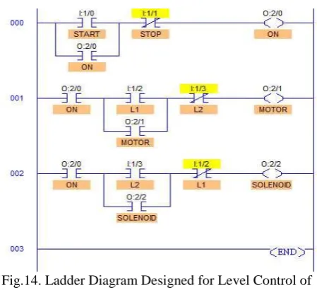
This system is designed in ladder diagram and then in FBD. The ladder diagram view is shown in Fig. 14.
Fig.14. Ladder Diagram Designed for Level Control of Two Tank System
This ladder diagram is in 3 rungs. FBD block is divided into three parts same as ladder diagram.
1. In Fig. 14 rung number 000 presents the logic to turn the lamp (denoted as ON) ON when START button is pressed and turn the lamp (denoted as ON) off when STOP button is pressed. Same logic is designed in the FBD block shown in Fig. 15, by changing the series connections in rung to AND gate and parallel connections in rung to OR gate. START is a push button so it will not store the value for continuously switching the lamp ON. So this input START is OR with the ON. Thus creating a loop. This loop can be break by the STOP switch connected through AND.
2. Rung number 001 presents the logic to turn the MOTOR ON when L1 is on, L2 is off and the process is ON. In FBD this is designed by replacing the series connection of ladder with AND gate in FBD and parallel connection of ladder with OR gate in FBD.
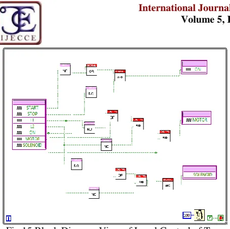
Fig.15 Block Diagram View of Level Control of Two Tank System
The above process is designed in LabVIEW using FBD blocks. The block diagram view of LabVIEW is shown in Fig 15.
This system was designed and tested on the embedded PLC with all hardware. It was found to work perfectly as per the desired requirements.
C. Alarm Annunciator System
In industrial process control, an annunciator panel is a system to alert operators of alarm conditions in the plant. Multiple back-lit windows are provided, each engraved with the name of a process alarm. Lamps in each window are controlled by hard-wired switches in the plant, arranged to operate when a process condition enters an abnormal state (such as high temperature, low pressure, loss of cooling water flow, or many others). Fig 16 shows an annunciator panel.
One common alarm sequence is, the light in a window will flash and a bell or horn will sound to attract the operator's attention when the alarm condition is detected. The operator can silence the alarm with a button, and the window will remain lit as long as the process is in the alarm state. When the alarm clears (process condition returns to normal), the lamps in the window go out.
Fig.16. Annunciator Panel
Embedded PLC can be used to design such an annunciator system. A system for checking one alarm signal was designed and tested with LED and Buzzer.
The system flow is as follows.
1. When error arise the LED flashes continuously and Buzzer starts ringing.
2. On acknowledgment of the error the Buzzer stops and LED becomes stable (stops flashing).
3. When the error is rectified and system is reset the LED stops.
This system is designed in ladder diagram and then in FBD. The ladder diagram view is shown in Fig. 17. The block diagram view of this system is as shown in Fig 18.
The ladder diagram consist 5 rungs. The flow is as follows.
1. When error occurs the buzzer starts and an extra element is also turned on to be used later. The buzzer stops when the error is acknowledged by pressing ack or is reset.
Fig.17. Ladder Diagram Designed for Alarm Annunciator 2. At the same time two timers start in loop in such a way that timer 0 is reset by timer 1. Input to timer 0 is through extra bit created in first rung. Output of timer 0 acts as input to lamp which needs to blink till the error is acknowledged by pressing ack. In FBD this timer logic is designed same as in ladder diagram i.e. both timer resetting each other. The outputs of timers are created as local variable and then used for loop action.
3. When ack is pressed the buzzer stops and the lamp becomes stable. This is done by ORing the input to lamp which is output of timer by an extra bit ex1.
4. This ex1 gets input from ack input. As the ack is push button ex1 is used in loop to keep itself activated till reset switch is pressed. A local variable is created for ex1 so as to use it in loop.
Copyright © 2014 IJECCE, All right reserved This system was designed and tested on the embedded
PLC with all hardware. It was found to work perfectly as per the desired requirements.
D. Systems Which Can Be Automated Using Embedded PLC
Following is a list of systems which can be automated using this embedded PLC.
1. Level Control
2. Alarm Annunciator System 3. Traffic signal Control 4. Car Parking
5. Two zone Parking Garage 6. Dirty-Water Pump System 7. Automatic Bottle Filling System 8. Running Lights
IV.
C
ONCLUSIONIn this paper a Programmable Logic Controller is designed with the ARM7 LPC2378 controller platform with full software support of LabVIEW. In addidtion to this three systems automatic bottle filling system, automatic level control system and alarm annunciator system were discussed and their system automation performed using the embedded PLC. These systems were designed and tested on the embedded PLC. FBD is found to be more user friendly than any other language of the IEC 61131-3 standard. The direct connections of the input and output ports to function blocks in FBD makes it easy to use and understand. The tedious task of addressing the elements is thus eliminated. Using LabVIEW for programming the embedded PLC has saved the efforts of programming the ARM processor in embedded C language.Programming the embedded PLC has thus become user friendly. Embedded PLC is found to be less costly to other PLC’s. As the processor board has all the IO ports available on it there will be very minor cost increase if user needs to increase the number of IO.
R
EFERENCES[1] Pornjit Pratumsuwan and Watcharin Pongaen, “An Embedded PLC Development for Teaching in Mechatronics Education”, 6th IEEE Conference on Industrial Electronics and Applications 2011 pp.1477-1481
[2] “Getting Started with the LabVIEW Embedded Module for ARM Microcontrollers 1.1,” National Instruments Corporation, 2008.
[3] J. Staunstrup and W. Wolf, “Data books of ARM7/ARM9”, Kluwer Academic Publishers, 1997.
[4] W. Bolton,“Programmable Logic Controllers”,Fourth Edition, Elsevier Newnes publications..
[5] Curtis D. Johnson, “Process Control Instrumentation
Technology”, Seventh Edition , Prentice-Hall, Inc.
[6] Selcuk Cihangir and Simon Kwan, Fermilab, USA, Marleigh Sheaff, University of Wisconsin, USA, Kerem Cankocak, Mugla University, Turkey “LabVIEW Tutorial, Laboratory Course On Interfaces And Data Acquisition”.
[7] “Creating a LabVIEW Palette” National Instruments
Corporation, 2013.
[8] “SIEMENS SIMATIC Function Block Diagram (FBD) for S7-300 and S7-400 Reference Manual” SIEMENS, Edition 03/2006. [9] Hugh Jack, “Automating Manufacturing Systems with PLC’s”
(version 4.7, April 14, 2005)
[10] “LPC 2377/78 Single-chip 16-bit/32-bit microcontrollers”, Product Data Sheet, NXP, Rev. 6.1 – 16 October 201.
A
UTHOR’
SP
ROFILESneha Goyanka
Born in April 1985 she earned her Bachelor of Engineering Degree in Instrumentation from North Maharashtra University, Jalgaon, Maharashtra, India in the year 2007. She is currently pursuing Masters
of Engineering in Electronics and
Telecommunication Engineering with VLSI and Embedded System as special subject from the University of Pune, Maharashtra, India.
She has worked as ASSISTANT PROFESSOR in Government College of Engineering, Jalgaon, Maharashtra, India from 2008 to 2011. Currently she is working on ARM processor and exploring its functions for system automation.
Rohita Patil
Born in September 1981, she earned her Bachelor of Engineering Degree in Electronics Engineering from Shivaji University, Kolhapur, Maharashtra, India in the year 2003, followed by Masters of Engineering in Electronics and Telecommunication Engineering from Dr. Babasaheb Ambedkar Technological University, Lonere in the year 2006.
She has worked as LECTURER in I2IT, Hinjewadi, Pune
Maharashtra, India form 2006 to 2010 . Currently she is working as ASSISTANT PROFESSOR at Smt. Kashibai Navale College of Engineering, Pune, Maharashtra, India. She has numerous papers published in various journals, publications etc.