http://dx.doi.org/10.4236/wjet.2015.33C036
Finite Element Modeling of Stamp Forming
Process on Fiber Metal Laminates
Xiaocen Dou
1, Sivakumar Dhar Malingam
2, Jae Nam
3, Shankar Kalyanasundaram
3 1Shanghai R & D Centre, Hyundai Heavy Industries, Shanghai, China2Center of Advanced Research on Energy, Technical University of Malaysia Malacca, Durian Tunggal, Malaysia 3Research School of Engineering, The Australian National University, Canberra, Australia
Email: [email protected]
Received 9 September 2015; accepted 16 October 2015; published 23 October 2015
Abstract
Fiber-metal laminates (FMLs) possess huge potential in mass-reduction strategy of automotive industry. In order to understand behavior of FMLs as they undergo stamp forming processes, finite element analyses of surface strain evolutions have been carried out. The simulations provide strains at locations within the layers of an FML, allowing better understanding of forming be- havior of the composite layer and its influence on the metal layers. Finite element analyses were conducted on two aluminum-based FMLs with different fiber-reinforced composites and ben-chmarked against monolithic aluminum alloy. The simulation results indicated that high stiffness of the reinforcement constrains flow of the matrix in the composite layer, which can be attributed to the distinguishing behavior of the FMLs compared to the monolithic aluminum alloy.
Keywords
Fiber Metal Laminates, Stamp Forming, Finite Element Modeling
1. Introduction
Continuous increases in fuel price and stricter environmental regulations have brought new priorities for auto-motive industries. By substituting steel components with lightweight material parts, there is a huge potential to cut down the weight of the vehicle, thus reducing the consumption of fuel and emission of exhaust fumes.
Fiber metal laminates (FMLs) is among the most innovative lightweight materials, which was designed to merge the formability of metal and advanced properties of composite materials into one material system. FMLs are created by bonding composite laminate plies to metal sheets. The first FML was introduced in 1978 [1], which possessed high strength and stiffness-to-weight ratio [2], excellent fatigue properties [3] and corrosion re-sistance [4]. However, the thermoset polymer based FML parts are made by lay-up process, which does not meet the demand of high-volume productions such as that of the automotive industry. Hence, to promote the use of FMLs in automotive applications, expansion in knowledge about forming performances of FMLs under the stamp forming process is required.
sections were first stamped, confirmed that FMLs have potential for superior formability characteristics to mo-nolithic aluminum, such as lower strain, less shape error and delamination [5]-[7]. Further studies were con-ducted on dome forming, found out that various combination of forming rate, process temperature, blank holder force and constituent material properties have significant effect on the forming performance of FMLs. By se-lecting optimum combination, FMLs could exhibit forming characteristics that are comparable to metals. [8]-[10].
Experimental analysis has limitations. For example, the strain distribution in areas of no visibility cannot be measured. To overcome such drawbacks, finite element modeling was implemented [11]-[13]. However, since these models did not simulate the exact plies-bonding structure of FML system, they were unable to explain the interaction of constituent and adhesive layers of FMLs forming process. To get a better insight of the forming behavior, this paper investigated the evolution of surface strains of each layer of FMLs, and benchmarked the results with the forming mode of monolithic aluminum.
2. Modeling
2.1. Finite Element Analysis Setup
A round-bottom cylindrical cup test was modeled using finite element analysis. The FML models were com-posed of three circular layers which have uniform initial diameter of 180 mm before the stamping process. The top and bottom aluminum layers are 0.5 mm in thickness, while the composite core layer has a thickness of 1 mm.
The model used in this research utilized a fully integrated version of quadrilateral shell element, in conjunc-tion with full projecconjunc-tion of warping stiffness (Element Type 16 and Hourglass 8 in LS-DYNA). This combina-tion is optimized for stability and accuracy of the numerical result [14], as well as enhancing the in-plane bend-ing behavior [15].
2.2. Material Properties of Constituent Layers
[image:2.595.171.457.499.705.2]Two types of fiber-reinforced thermoplastics, Curv® and Twintex®, were modeled as the core layer, whose me-chanical properties are listed in Table 1. Curv® is a self-reinforced polypropylene that has a plain woven struc-ture of polypropylene fiber bundled and a polypropylene matrix. Twintex® is a fiber-reinforced polypropylene with a balanced 2/2 twill weave of glass fibers. These two fiber-reinforced materials exhibit apparent differences when they are deformed, as depicted in Figure 1 [16]. Curv® shows good ductility and high strain value at fail-ure, whereas Twintex® is stiffer and fails at a lower strain value. The constitutive equations for Curv® and Twintex® [14] are used to develop a user-defined material subroutine employed in the model.
Table 1. Mechanical properties of Curv®, Twintex® and aluminum alloy 2024-T3.
Curv® (1 mm) Twintex® (1 mm) A2024-T3
Nominal weight (g/m2) 920 1458 2710
Tensile Modulus (GPa) 4.2 15.3 73
Tensile Strength (MPa) 120 360 324
Tensile strain to failure 0.24 0.12 0.19
3. Modeling Result
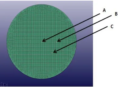
Three points of interest on the blank were investigated, as shown in Figure 2; 1) Point A at the pole of dome, 2) Point B, 40 mm from the pole along the fiber-direction, and 3) Point C, 40 mm along 45˚ direction to the fiber orientation from the pole.
3.1. Strain Paths at Point A—The Pole
Throughout the stamping process, forming modes at the pole in both Curv®-FMLs and Twintex®-FMLs are identical. As shown in Figure 3(a) and Figure 3(b), paths of strains in top, core and bottom layers coincide with that of a monolithic aluminum alloy. It is indicated that the pole in either aluminum or fiber-reinforced layer is subjected to biaxial stretching. The presence of the fiber-reinforced layer has little effect on the forming mode. Nevertheless, the magnitude of major strain within Curv®/Twintex® is higher than that of aluminum alloy, which can be attributed to the lower tensile modulus of the fiber-reinforced polypropylene compared to aluminum al-loy.
3.2. Strains Path at Point B—Side-Wall along Fiber Direction
Points on side-walls of FMLs along the fiber direction are more affected by the fiber-reinforced layer than at the pole. For Curv®-FMLs, as depicted in Figure 4(a), strain path of the Curv® layer is that of uniaxial tension. This is due to the strong constraint of fiber along tangential direction preventing the material from flowing smoothly. The forming mode of Curv® layer drove the bottom layer to deviate from the path of drawing towards uniaxial tension. For Twintex®-FMLs, as illustrated in Figure 4(b), the Twintex® and the bottom layer follow a strain pattern of biaxial stretch, while the top layer remains in drawing mode, same as the monolithic aluminum sheet. Twintex® has crucial influence on the bottom layer, though the top layer is almost unaffected. Regarding mag-nitude of strains, major strains in Curv®-FMLs are close to that of monolithic aluminum alloys, while those of Twintex®-FMLs are slightly lower.
3.3. Strains Path at Point C—Side Wall along 45˚ to Fiber Direction
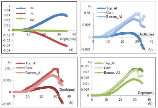
Strain paths of Point C in Curv®-FMLs and Twintex®-FMLs are shown in Figure 5. For Curv®-FMLs, top layer is hardly affected by the Curv® layer, while the bottom layer is transformed to the uniaxial tension region, al-most identical to the strain path of Curv®. For Twintex®-FMLs, the strain pattern of top layer was more affected by the Twintex® layer compared to the bottom layer. The forming mode of Twintex® is plane strain, indicating difficulties for the material to flow along the tangential direction. εx, εy and εxy at point C of both FMLs are
sig-nificantly different from their counterparts in monolithic aluminum, while these strains at point B share the same trend with that in monolithic aluminum alloy. The comparisons are illustrated in Figure 6 and Figure 7. At Point B, εx and εy are approximately same in value but possess different signs, while the magnitude of εxy is
neg-ligible. This indicates a typical drawing mode at side wall, the resultant of 1) tensile strains in radial direction and 2) compression in tangential direction within the aluminum layer.
At Point C, in contrast, magnitude of εxy is predominant compared to those of εx and εy. This strongly implies
Figure 2. Points of interest at pole and on side-walls on the stamp forming blank.
Figure 3. Strain diagrams of point A of (a) Curv®-FMLs and (b) Twintex®-FMLs at room temperature (25˚C).
Figure 4. Strain diagrams of point B of (a) Curv®-FMLs and (b) Twintex®-FMLs at room temperature (25˚C).
[image:4.595.125.505.415.542.2] [image:4.595.119.507.569.707.2]
Figure 6. Comparison of strain component at Point B on (a) monolithic Alumi-num and (b) Curv®-FMLs at room temperature (25˚C).
Figure 7. Comparison of strain component at Point C on (a) monolithic
Alumi-num and (b) Curv®-FMLs at room temperature (25˚C).
4. Conclusions
This work involved simulations of stamping process on fiber-metal laminates by using finite element modeling. Two FMLs with different core composite layer, Curv® and Twintex® were investigated. It focused on the strain evolutions during the forming process in each layer of the FMLs, which gave innovative information compared to previous works. Based on comparisons of strain paths at points of interest in FMLs and monolithic aluminum, their different forming behaviors were unveiled. Two basic modes of deformation underwent by sheet metal forming, drawing and stretching, were also found in all layers of FMLs during the stamp forming.
Around the pole area, forming modes in all three layers highly coincide with that of the monolithic aluminum, while on the side-wall, strain path could deviate from that of aluminum sheet, depending on the material proper-ties of the core layer.
[image:5.595.178.451.307.494.2]References
[1] Villanueva, G.R. and Cantwell, W.J. (2004) The High Velocity Impact Response of Composite and FML-Reinforced Sandwich Structures. Composite Science and Technology, 64, 35-54.
http://dx.doi.org/10.1016/S0266-3538(03)00197-0
[2] Beumler, T., Pellenkoft, F., Tillich, A., Wohlers, W. and Smart, C. (2006) Airbus Costumer Benefit from Fiber Metal Laminates. Airbus Deutschland GmbH, Ref. no: L53pr0605135-Issue 1, 1-18.
[3] Alderliesten, R. and Benedictus, R. (2007) Fiber/Metal Composite Technology for Future Primary Aircraft Structures. The 48th AIAA/ASME/ASCE/AHS/ASC Structures, Structural Dynamics, and Materials Conference, Honolulu, 23-26 April, 2007, 1-12. http://dx.doi.org/10.2514/6.2007-2404
[4] Alderliesten, R. (2009) On the Development of Hybrid Material Concepts for Aircraft Structures. Recent Patents Eng, 3, 25-38. http://dx.doi.org/10.2174/187221209787259893
[5] Compston, P., Cantwell, M.J., Cardew-Hall, M., Kalyanasundaram, S. and Mosse, L. (2004) Comparison of Surface Strain for Stamp Formed Aluminum and an Aluminum-Polypropylene Laminate. Journal of Materials Science, 39, 6087-6088. http://dx.doi.org/10.1023/B:JMSC.0000041707.68685.72
[6] Mosse, L., Compston, P., Cantwell, W.J., Cardew-Hall, M.J. and Kalyanasundaram, S. (2005) The Effect of Process Temperature on the Formability of Polypropylene Based Fibre-Metal Laminates. Composites: Part A, 36, 1158-1166. http://dx.doi.org/10.1016/j.compositesa.2005.01.009
[7] Mosse, L., Compston, P., Cantwell, W.J., Cardew-Hall, M.J. and Kalyanasundaram, S. (2006) Stamp Forming of Po-lypropylene Based Fibre-Metal Laminates: The Effect of Process Variables on Formability. Journal of Materials Pro-
cessing Technology, 172, 163-168. http://dx.doi.org/10.1016/j.jmatprotec.2005.09.002
[8] Gresham, J., Cantwell, W.J., Cardew-Hall, M.J., Compston, P. and Kalyanasundaram, S. (2006) Drawing Behaviour of Metal-Composite Sandwich Structures. Composite Structures, 75, 305-312.
http://dx.doi.org/10.1016/j.compstruct.2006.04.010
[9] Sexton, A., Cantwell, W.J. and Kalyanasundaram, S. (2012) Stretch Forming Studies on a Fibre Metal Laminate Based on a Self-Reinforcing Polypropylene Composite. Composite Structures, 94, 431-437.
http://dx.doi.org/10.1016/j.compstruct.2011.08.004
[10] Kalyanasundaram, S., DharMalingam, S., Venkatesan, S. and Sexton, A. (2013) Effect of Process Parameters during Forming of Self-Reinforced-PP Based Fiber Metal Laminate. Composite Structures, 97, 332-337.
http://dx.doi.org/10.1016/j.compstruct.2012.08.053
[11] Hashagen, F., Schellekens, J.C.J., de Borst, R. and Parisch, H. (1995) Finite Element Procedure for Modelling Fiber Metal Laminates. Composite Structures. 32, 255-264. http://dx.doi.org/10.1016/0263-8223(95)00083-6
[12] Mosse, L., Compston, P., Cantwell, W.J., Cardew-Hall, M.J. and Kalyanasundaram, S. (2006) The Development of a Finite Element Model for Simulating the Stamp Forming of Fibre-Metal Laminates. Composite Structures, 75, 298- 304. http://dx.doi.org/10.1016/j.compstruct.2006.04.009
[13] Davey, S., Das, R., Cantwell, W.J. and Kalyanasudaram, S. (2013) Forming Studies of Carbon Fibre Composite Sheets in Dome Forming Processes. Composite Structures, 97, 310-316. http://dx.doi.org/10.1016/j.compstruct.2012.10.026
[14] Venkatesan, S. (2012) Stamp Forming of Composite Materials: An Experimental and Analytical Study. Ph.D. Thesis, The Australian National University, Canberra.
[15] Dhar Malingam, S. (2011) An Investigation into the Forming Behavior of Metal Composite Hybrids. Ph.D. Thesis, The Australian National University, Canberra.
![Figure 1. Stress-strain curves for curv® and Twintex® (Glass/PP) [16].](https://thumb-us.123doks.com/thumbv2/123dok_us/8057659.775561/2.595.171.457.499.705/figure-stress-strain-curves-curv-twintex-glass-pp.webp)