Tetra-Frequency Microstrip Antenna for Wireless
Applications
Arpita Sen
Electronics and Communication Engineering Department, Birla Institute of Technology, Mesra,
Ranchi-835215, INDIA
Neela Chattoraj
Electronics and Communication Engineering Department, Birla Institute of Technology, Mesra,
Ranchi-835215, INDIA
ABSTRACT
In this paper, the design, fabrication and measurement of a microstrip patch antenna is reported which can be operated at four frequencies – 5.215 GHz, 5.5 GHz, 5.69 GHz and 6.16 GHz. The simulation is done using IE3D software.
Keywords
Microstrip patch antenna, tetra frequency, quadruple frequency, HIPERLAN, multi-frequency antennas, 5 GHz band
1.
INTRODUCTION
The demand of antennas for different systems and standards with properties like reduced size, broadband, multiband operation, moderate gain etc that work in the defined range of frequencies has increased with increasing use of microwave mobile communication systems. Some of such prevalent frequency bands include 900 MHz, 1.8 GHz, 2.4 GHZ, 5 GHz, 6 GHz, etc. Since higher frequencies result in shorter wavelengths, the wavelength of a 900 MHz device is longer than that of others. But, each band has its own advantages and disadvantages. The 900 MHz frequency has interference issues with other devices using this band, particularly cordless phones. The 2.4 GHz frequency band is also crowded with interfering devices like other Wi-Fi access points, microwave ovens, cordless phones, Bluetooth devices, etc. The 5 GHz band in comparison is considerably cleaner in most areas. Operating at the 5GHz radio bands has several advantages over the more common 2.4GHz band:
Better penetration
Less radio congestion due to larger number of non-overlapping channels
Better for non line of site operation
Better scatter
No abnormal absorption by water or damp
But, due to unavailability of certain frequency bands in certain parts of the world, there is a need to have antennas that can work at multiple frequencies. The multi-frequency characteristics of a microstrip antenna are studied here using dual-patch configuration. Microstrip patch antennas have received considerable attention for wireless communication because of its attractive features. Literatures are available for microstrip patch antennas with parasitic patches [14-17] and these types of patches are also investigated for mobile communication [18].
2.
DESIGN
AND
SIMULATION
In this paper, the design of a microstrip patch antenna is reported which can be operated at four frequencies for 5 GHz
configuration. The patches are placed on a dielectric slab of thickness 1.59 mm and dielectric constant 2.55 with a ground plane on the bottom surface of the dielectric slab. The PTFE (Polytetrafluroethylene) substrate with loss tangent of 0.0001 is used. The antenna was fed at the common corner of the geometry.
Fig 1: Designed & Fabricated Tetra-frequency antenna
The antenna is a dual-patch structure of two square patches with corner truncated and slit loaded. In order to achieve desired resonance frequencies, the dimensions of both the square patches are optimized after a large number of simulations. Slit position and slit dimension are adjusted so as to get the required results for all the 4 frequencies.
Table1. Results for return loss with variation of slit position
Structure Return Loss
f1 f2 f3 f4
Without slit -12 dB -13.5 dB -18.5 dB -6.5 dB With top
patch corner slit
- -14 dB -21 dB -6 dB
With both
28 The simulation software used for simulation of the antenna is
IE3D. It is full wave electromagnetic simulation software for the microwave and millimeter wave integrated circuits that takes into account the effect of co-axial SMA connector, by which the antenna was fed. The software on the principles of Method of moments using the function f (g) = h. (where, ‘f (g)’ - a known linear operator, of an unknown function ‘g’, and ‘h’ - the source or excitation function) ‘g’ is to be calculated, when ‘f’ and ‘h’ are known. ‘g’ can be expanded as a linear combination of ‘n’ terms consisting of: ‘n’ number of unknown constants ‘an’ and ‘n’ number of known functions ‘gn’. ‘gn’ is called basis functions or expansion functions. In IE3D simulation, these unknowns are obtained by using Green’s function in the electric field integral equation formulation satisfying boundary conditions at the microstrip patch metallization, since microstrip antenna structure is of mixed dielectric type. The resulting set of linear equations yields a matrix equation. The current distribution on the metal patch and the required quantities can be obtained from the solution of this matrix equation.
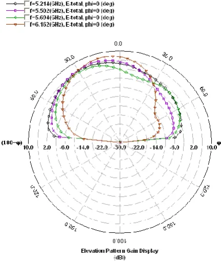
[image:2.595.316.538.94.365.2]The simulated results for radiation patterns of the antenna at phi=0 degree are shown in Fig 2a. It is seen that at all the four resonance frequencies the antenna radiate linearly polarized far field along the broadside direction. The antenna does not radiate accurately in the broadside direction but the radiation pattern is slightly tilted which is seen from the simulated radiation pattern. This tilting occurs because the geometry of the radiating patches is not symmetrical.
Fig 2a: Simulated radiation pattern of the antenna for phi=0 degree
[image:2.595.57.273.384.640.2]The radiation pattern at phi=90 degree is given as:
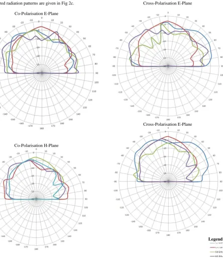
The measured radiation patterns are given in Fig 2c.
Co-Polarisation E-Plane
Co-Polarisation H-Plane
Cross-Polarisation E-Plane
Cross-Polarisation E-Plane
[image:3.595.94.539.71.593.2]Legend:
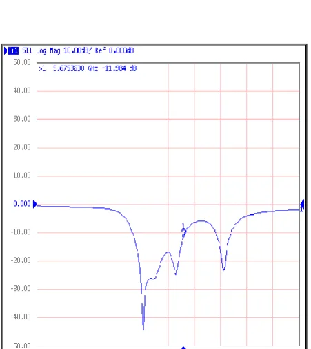
30 The simulated and measured plot for return loss of the antenna
[image:4.595.316.567.90.312.2]is shown in Fig 3.
Fig 3: Simulated and Measured return loss of the antenna
[image:4.595.57.289.107.315.2]The simulated plot for VSWR of the antenna is shown in Fig 4.
Fig 4: Simulated VSWR of the antenna
Fig 5: Measurement Setup for radiation pattern
3.
CONCLUSION
The design and performance of a tetra-frequency microstrip antenna for the application in four frequencies for 5 GHz band (5.215 GHz, 5.5 GHz, and 5.69 GHz) and 6.16 GHz are described here. The frequencies are selected by studying the existing work for quadruple frequency antenna [19, 20, 21], so that the antenna contains a new set of frequencies. One of the uses of this multi-frequency antenna can be in automobiles where:
5 GHz band (Automobile IPTV) – can be used for better QoS providing superior image and audio quality and interference-free transmission
6 GHz (Automatic/Electronic Toll Collection (ETC)) - can be used to allow charging tolls without vehicles having to slow down.
4.
ACKNOWLEDGMENTS
[image:4.595.55.281.317.570.2]5.
REFERENCES
[1] J. S. Roy and J. Ghosh, “A Multifrequency Microstrip Antenna”, Microwave and Optical Technology Letters, USA, vol. 46, no.1, pp. 63-65, July 05, 2005.
[2] F. Yang, X-X Zhang, X. Ye and Y. Rahmat-Samii, “Wide-Band E-Shaped Patch Antennas for Wireless Communications”, IEEE Trans. Antennas and Propagat., Vol. AP-49, 2001, pp. 1094– 1100.
[3] J. S. Roy, N. Chattoraj and N. Swain, “Short Circuited Microstrip Antennas For Multi-band Wireless Communications”, Microwave and Optical Technology Letts, Vol. 48, 2006, pp. 2372 – 2375.
[4] X. Jing, Z. Du and K. Gong, “A Compact Multiband Planar Antenna for Mobile Handsets”, IEEE Antennas and Wireless Propagation Letters, Vol. 5, 2006, 343 – 345.
[5] E. S.Angelopoulos, A. Z. Anastopoulos, D. I. Kaklamani, A. A. Alexandridis, F.Lazarakis and K. Dangakis, “Circular and Elliptical CPW-Fed Slot and Microstrip-Fed Antennas for Ultrawideband Applications”, IEEE Antennas and Wireless Propagation Letts, Vol. 5, 2006, pp. 294 – 297.
[6] J. S. Roy and N. Swain, “A New Dual-Frequency Microstrip Patch Antenna for GPS and Bluetooth Systems”, ICMARS2006, Jodhpur, Dec.18-22, 2006.
[7] J. S. Roy, N. Chattoraj and N. Swain, “New Dual-Frequency Microstrip Antennas for Wireless Communication”, Romanian Journal of Information Science and Technology, Vol. 10, 2007, pp. 113 –119.
[8] J. S. Roy and M. Thomas, “Theoretical and Experimental Investigations on a New Proximity Coupled Dual Frequency Microstrip Antenna for the Application in Wireless Communication”, Microwave Review, Vol. 13, 2007, pp. 12 – 15.
[9] J. S Roy, and M. Thomas, “Compact and Broadband Microstrip Antennas for Next Generation High Speed Wireless Communication Using HIPERLAN/2”, Intl Journal. of Microwave Science and Technology, Vol. 2007, 2007, pp. 1-4.
[10] J. S. Roy and M. Thomas, “Miniaturized Broadband Microstrip Antennas for HIPERLAN/2 Application”, Romanian Journal of Information Science and Technology, Vol. 10, No. 4, 2007, pp. 355 – 360.
[11] B.-H. Sun, J.-F. Li and Q.-Z. Liu, “Compact Broadband Printed Antenna for Multi-functional Mobile Terminals”, Journal of Electromagnetic Waves and Applications, Vol. 22, No. 8-9, 2008, pp. 1292 – 1298.
[12] J. S. Roy and M. Thomas, “Design of A Circularly Polarized Microstrip Antenna for WLAN”, Progress In Electromagnetic Research(PIER) M, Vol. 3, 2008, pp. 79 – 90.
[13] J. S. Roy, M. Thomas and J. Ghosh, “Miniaturized Broadband Circularly Polarized Microstrip Antenna for WLAN”, Intnl. Jnl. of Microwave and Optical Technology Letters (IJMOT), to be published.
[14] R. Garg, P. Bhartia, I. J. Bahl and A. Ittipiboon, Microstrip Antenna Design Handbook, Artech House, 2001.
[15] I. J. Bahl and P. Bhartia, “Microstrip Antennas”, Artech House, Dedham, Mass 1980.
[16] K. L Wong, Compact and Broadband Microstrip Antennas, Wiley, 2002.
[17] G. Kumar and K. P. Ray, Broadband Microstrip Antennas, Artech House, Boston, 2003.
[18] W. Qin, “A Novel Patch Antenna with A T-shaped Parasitic Strip for 2.4/5.8 GHz WLAN Applications”, Journal of Electromagnetic Waves and Applications, Vol. 21, No. 15, 2007, pp. 2311 – 2320.
[19] D. Segovia-Vargas, F. J. Herraiz-Martinez, E. Ugarte-Munoz, L. E. Garcia-Ugarte-Munoz, and V. Gonzaalez-Posadas,"QUAD-FREQUENCY
LINEARLY-POLARIZED AND DUAL- FREQUENCY
CIRCULARLY-POLARIZED MICROSTRIP PATCH ANTENNAS WITH CRLH LOADING", Progress In Electromagnetics Research, Vol. 133, 91-115, 2013
[20] Uduwawala DN, Jayasinghe JMJW, "Novel Quad-band Patch Antenna Design for Wireless Communications in 2.4, 5.2, 5.6 and 5.8 GHz Bands using Genetic Algorithm Optimization", International Journal of Engineering and Technology, 1 (4) (2012) 466-471, ©Science Publishing Corporation, www.sciencepubco.com/index.php/IJET.