International Journal of Emerging Technology and Advanced Engineering
Website: www.ijetae.com (ISSN 2250-2459, Volume 2, Issue 3, March 2012)310
Tuning of PID Controller for DC Servo Motor using
Genetic Algorithm
Bindu R.
1, Mini K. Namboothiripad
21,2
Department of Electrical Engineering,
Fr. C. Rodrigues Institute of Technology,(Affiliated to Mumbai University) Vashi, Navimumbai.
1[email protected] 2[email protected]
Abstract—The position control study of DC servo motors is
very important since they are extensively deployed in various servomechanisms. Normally PID controllers are used to improve the transient response of DC servo motors. At present, most tuning methods are designed to provide workable initial values, which are then further manually optimized for a specific requirement. This paper presents a flexible and fast tuning method based on genetic algorithm (GA) to determine the optimal parameters of the PID controller for the desired system specifications. Simulation results show that a wide range of requirements are satisfied with the proposed tuning method.
Keywords—DC servomotor, Genetic Algorithm,
Optimization, PID controller, PID Tuning, Transient response.
I. INTRODUCTION
Electrical motor servo systems are indispensable in modern industries. Servo motors are used in a variety of applications in industrial electronics and robotics that includes precision positioning as well as speed control [9]. Servomotors use feedback controller to control the speed or the position, or both. The basic continuous feedback controller is PID controller which possesses good performance. However is adaptive enough only with flexible tuning. Although many advanced control techniques such as self-tuning control, model reference adaptive control, sliding mode control and fuzzy control have been proposed to improve system performances, the conventional PI/PID controllers are still dominant in majority of real-world servo systems [1].
To implement a PID controller the proportional gain KP,
the integral gain KI and the derivative gain KD must be
determined carefully. Many approaches have been developed to determine PID controller parameters for single input single output (SISO) systems.
In this paper genetic algorithm is used to calculate these parameters. Genetic algorithm is a computational procedure that mimics the natural process of evolution [12]. It works by evolving a population of solutions over a number of generations. For each generation, solutions are selected from the population based on the fitness value. These solutions by crossover (merging previous solutions) and by mutation (modifying the solutions) generate new population. Since it searches many peaks in parallel, the trapping at local minima is avoided [6].
II. SYSTEM MODEL
As reference we consider a DC servo motor as shown in figure 1. A simple mathematical relationship between the shaft angular position and voltage input to the DC motor may be derived from physical laws. In the point of control system, DC servo motor can be considered as SISO plant [5]. Therefore, complications related to multi-input system are discarded. DC servo motors have the field coil in parallel with the armature. The current in the field coil and the armature are independent of one another. As a result, these motors have excellent speed and position control.
Ea(t)
+
-Ra
L a
Eb(t)
+
-Tm(t)
[image:1.612.349.549.551.655.2]θ(t) Fixed Field
International Journal of Emerging Technology and Advanced Engineering
Website: www.ijetae.com (ISSN 2250-2459, Volume 2, Issue 3, March 2012)311 The dynamic behaviour of the DC motor is given by the following equations [8], and can be represented by the block diagram as shown in figure 2.
)
(
)
(
)
(
)
(
s
R
I
s
L
sI
s
E
s
E
a
a a
a a
b)
(
)
(
s
K
I
s
T
m
t a)
(
)
(
s
K
s
s
E
b
b
)
(
)
(
)
(
s
J
s
2D
s
s
T
m
m
m
where, Ra=Armature resistance in ohm, La=Armature inductance in henry, ia=Armature current in ampere, ea=Armature voltage in volts, eb=Back EMF in volts, Kb=Back EMF constant in volt/(rad/sec), Kt=Torque constant in N-m/Ampere, Tm=Torque developed by the motor in N-m, θ(t)=Angular displacement of shaft in radians, J=Moment of inertia of the motor and load in Kg-m2/rad, Dm=Frictional constant of motor and load in N-m/(rad/sec).
+
-Ea(s) θ(s)
) s (J
1 2 m Dms )
s (L
1
a Ra
Eb(s)
Kb s
[image:2.612.338.555.148.252.2]Kt
Fig. 2. Block Diagram representation of a DC Servo motor
After simplification and taking the ratio of
) ( ) ( s E s a
, the
transfer function will be as below,
) 1 ...( ) ( ) ( )
( 3 2
s D R K K s D L J R s J L K s G m a t b m a m a m a t
III. PIDCONTROLLER DESIGN
Consider the transfer function of the DC servo motor as,
[image:2.612.54.283.366.437.2])
2
(
...
)
(
1 2 2 33
s
a
s
a
s
a
K
s
G
By comparing equations (1) and (2), a3=LaJm, a2=RaJm+LaDm and a1=KbKt+RaDm.
Transfer function of the PID controller can be written as,
s K s K K s
C I D
P
) (
+
-θr(s) θ(s)
s) a a s (a K 1 2 2 3
3 s
t s I K s KD P K + ++
Fig. 3. Block Diagram representation of a DC Servo motor with PID controller.
Then the overall transfer function for a unity feedback system will be,
) ( ) ( 1 ) ( ) ( ) ( s c s G s C s G s T
which can be calculated as,
K K Ks K s K K a s a s a K s K s K K s T I P D I P D 2 1 3 2 4 3 2 ) ( ) ( ) (
Thus the actual pole locations are the roots of the equation, ) 3 ...( 0 ) ( 2 1 3 2 4
3s a s a K K s K KsK K
a D P I
But the required pole locations are the roots of the equation,
)
4
....(
0
)
)(
2
(
s
2
w
ns
w
n2KK
Ds
2
KK
Ps
KK
I
where,
andw
nare the transient parameters from therequired transient response.
Comparing the equations (3) and (4) we will get 5 equations for solving three unknowns, KP, KI and KD, and hence optimization is required. Also the parameter determination process must be performed as fast as possible for the given system.
By the conventional Ziegler Nichols method, sustained oscillation is obtained by increasing the KP value from zero to critical. The measured frequency and gain of this oscillation are used to determine the PID parameters [7]. Since this technique depends on a generic model, the design objectives will almost always not be met.
International Journal of Emerging Technology and Advanced Engineering
Website: www.ijetae.com (ISSN 2250-2459, Volume 2, Issue 3, March 2012)312
IV. GENETIC ALGORITHM
The objective of the Genetic algorithm (GA), based on the natural process of evolution, is to find the optimal solution to a problem. GA works on a collection of several alternative solutions called population. Each solution or individual in the population is called chromosome and individual character in this is called genes. To obtain better solutions (population) from existing one, a new generation is evolved in each iteration of the GA [10].
The generation gap is the fraction of individuals in the population that are replaced from one generation to the next. Based on this, there are two basic GA approaches, called simple GA and steady state algorithm. Generation gap is equal to one in the simple GA and is less than one for the other approach.
Generation of a new population involves various steps. First evaluate each individual of the population by a user defined fitness function, which is opposite to the error function. Then highly fit individuals are selected from the population for reproduction. Selected individuals form pairs called parents. Different operations for reproduction are crossover and mutation.
In the crossover operation, portions of two parents are combined to produce two new individuals, called offspring. This provides a mechanism for the chromosomes to mix and match their desirable qualities in forming offspring. For each pair of parents, crossover is performed with a crossover probability Pc. New features can be introduced into a population by mutation. It produces random changes in the offspring with a probability called mutation probability, PM. Crossover is the main operation to search the solution space, but does not guarantee the reachability of the entire solution space with a finite population size. Mutation improves search space by introducing new genes into the population.
With crossover and mutation there is a high risk that the optimum solution could be lost as there is no guarantee that these operators will preserve the fittest string [2].
To counteract this, a mechanism is used in which, the best individual from a population is saved in the new population. Neighbours of the good solutions are also included in the new generation to improve the search process. When these neighbour solutions of the existing chromosome are evaluated by the algorithm, faster convergence with finer tuning could be achieved. Thus a considerable improvement in the solution quality could be obtained.
In GA the initial generation can be random or user specified.
After the reproduction, new generation will replace the old one and evolve until some stopping criterion is met.
V. PIDTUNING BY GA
The major objective of the GA is to determine the optimal values of the PID controller parameters to improve the transient response of the system. To achieve this, the algorithm considers the maximization of an objective function. This objective function provides a means for evaluating the performance of the PID controller with the determined gain parameters, so that an optimized controller would be developed by the best individual.
When applied to the PID controller design problem, the genes are the gain values of the controller KP, KI, and KD which are to be determined. Each chromosome contains a complete set of the genes needed to define uniquely a trial solution. The fitness of each chromosome is evaluated using the error criterion, which is used as the basis of selection for the chromosomes in the next generation [11].
During the optimization process, the required poles and the actual closed loop poles are used by the genetic algorithm. In each generation, according to the controller parameters, closed loop poles are determined. The tuning algorithm searches the optimal parameters for the PID controller with the help of these closed loop poles.
We use a population size of 20, and terminate the process after 100 generations. In the algorithm, single point crossover process was employed. Neighbours of the good chromosomes are calculated from the average of the good solutions.
In each generation, all solutions in the population are evaluated by a fitness function which can be considered as the inverse of the error function. Error E can be calculated by comparing the actual and required closed loop pole locations. It can be formulated as,
E=α(EOS)+β(ETs)+γ(ETd)+δ(Eon)+λ(Eof)……..(5)
where Eos is the error in percentage overshoot, ETs is the
error in settling time, ETdis the error in peak time, and Eon
and Eof are the errors in the location of the real poles.
In this function, the variables α, β γ, δ and λ are the weightage factors. By adjusting these factors, the most appropriate PID controller parameters to achieve the required closed loop response can be obtained.
International Journal of Emerging Technology and Advanced Engineering
Website: www.ijetae.com (ISSN 2250-2459, Volume 2, Issue 3, March 2012)313 After these reproduction methods, replace the entire population with the offsprings, neighbours of good solutions and the best solution.
Now continue the process of evaluation, reproduction etc, for a fixed number of generations to get a better solution. Algorithm can be summarized as,
Initialize the population;
while predetermined termination condition not satisfied;
{
1. Evaluate all these solutions with the fitness
function, which can be the inverse of error function.
2. Select some highly fit solutions.
3. Pair them as parents and perform crossover
operation to generate offsprings.
4. Perform mutation by slightly changing some
random solution.
5. Generate some solutions in the neighbourhood of
good solutions by taking the average of good solutions.
6. Save the best solution.
7. Replace the entire population with these
offsprings, neighbours of good solutions and the best solution.
}
VI. RESULT
Optimized gain values of PID controller are obtained with the implementation of GA based PID controller in MATLAB. For implementation of DC Servomotor the following parameters are considered [3].
Ra=2.45 ohm, La=0.035 H, Kb=1.2 volt/(rad/sec),
J=0.022Kg-m2/rad , B=0.5*10-3 N-m/(rad/sec).
Thus the overall transfer function of the system is given as,
s
s
s
s
G
441
.
1
0539
.
0
00077
.
0
2
.
1
)
(
3 2
Settling time of this system with unity feedback is 4.59sec without any compensation. It can be reduced and hence the required transient response can be achieved by using PID controller.
Genetic algorithm for PID controller tuning is implemented and performed in MATLAB with various values of required response.
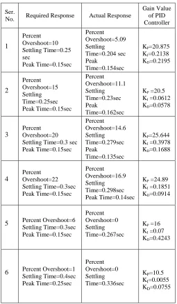
Calculated gain values of the PID controller are given in Table I. for different values of required response.
Actual response is calculated from the step response of the compensated system. It is observed that for a wide range of requirements, tuning is done and actual response is found to be better than the required response.
TABLE I
PARAMETERS OF THE PID CONTROLLED SYSTEMS FOR DIFFERENT VALUES OF REQUIRED RESPONSE
Ser.
No. Required Response Actual Response
Gain Value of PID Controller
1
Percent Overshoot=10 Settling Time=0.25 sec
Peak Time=0.15sec
Percent Overshoot=5.09 Settling Time=0.204 sec Peak
Time=0.154sec
KP=20.875 KI=0.2138 KD=0.2195
2
Percent Overshoot=15 Settling Time=0.25sec Peak Time=0.15sec
Percent Overshoot=11.1 Settling Time=0.23sec Peak
Time=0.162sec
KP =20.5 KI =0.0612 KD=0.0578
3
Percent Overshoot=20 Settling Time=0.3 sec Peak Time=0.15sec
Percent Overshoot=14.6 Settling Time=0.279sec Peak
Time=0.135sec
KP=25.644 KI =0.3978 KD=0.1688
4
Percent Overshoot=22 Settling Time=0.3sec Peak Time=0.15sec
Percent Overshoot=16.9 Settling Time=0.298sec Peak Time=0.14sec
KP =24.89 KI =0.1851 KD=0.0914
5 Percent Overshoot=6 Settling Time=0.3sec Peak Time=0.15sec
Percent Overshoot=0 Settling Time=0.267sec
KP =16 KI =0.07 KD=0.4243
6 Percent Overshoot=1 Settling Time=0.4sec Peak Time=0.25sec
Percent Overshoot=0 Settling Time=0.336sec
[image:4.612.317.572.240.678.2] [image:4.612.317.572.240.689.2]International Journal of Emerging Technology and Advanced Engineering
Website: www.ijetae.com (ISSN 2250-2459, Volume 2, Issue 3, March 2012)314 The step response for the uncompensated system and the compensated system to achieve 1% overshoot, 0.25 sec. peak time and 0.4 sec. settling time is given in figure 4.
[image:5.612.67.288.207.379.2]It is seen that settling time of actual response is 0.336 sec. and the percent overshoot is zero.
Fig. 4. Step response for the uncompensated system and compensated
system for % OS=1, Tp= 0.25 sec and Ts=0.4sec.
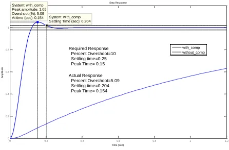
Similarly the step response for the uncompensated system and the compensated system to achieve 10% overshoot, 0.15 sec. peak time and 0.25 sec. settling time is given in figure 5.
Fig.5.Step response for the uncompensated system and compensated
system for % OS=10, Tp= 0.15 sec and Ts=0.25sec.
From these step responses, it is seen that the gain values of the PID controller are optimized to achieve the desired response.
VII.CONCLUSION
The genetic algorithm based PID tuning provides much better results compared to the conventional methods.
The conventional method is good for getting the initial values of the PID tuning which needs to be modified.
In the designed PID controller tuning with GA, the actual response is found to be satisfying the required value. PID controller gain values depend upon the range selected for the initial population. In our implementation, KP values are selected in the range of 10 to 30, KI in the range of 0.001 to 0.55 and the KD in the range of 0.001 to 0.5. It is observed that within this range tuning is done effectively. The range of requirement can be widened by increasing the range of initial population but the number of generations required to converge to optimal value may increase.
REFERENCES
[1] Guomin Li and Kai Ming Tsang, “Concurrent Relay-PID Control for
Motor Position Servo Systems”, International Journal of Control, Automation, and Systems, vol. 5, no. 3, June 2007.
[2] Aytekin Bagis, “Determination of the PID Controller Parameters by
Modified Genetic Algorithm for Improved Performance”, Journal of information science and engineering 23, 1469-1480 (2007).
[3] Neenu Thomas, Dr. P. Poongodi,” Position Control of DC Motor
Using Genetic Algorithm Based PID Controller”, Proceedings of the World Congress on Engineering 2009 Vol II, WCE 2009, July, 2009.
[4] Chuck Lewin, “Tuning Servomotors”, CEO of Performance Motion
Devices.
[5] Dong-Seog Bae and Jang-Myung Lee, “Unknown Parameter
Identifier Design of Discrete-Time DC Servo Motor Using Artificial Neural Networks”, Transactions on Control, Automation and Systems Engineering Vol. 2, No. 3, September, 2000.
[6] M. Gen, and R. Cheng, “Genetic algorithms and engineering
design”, (John Wiley & Sons, Inc., 1997).
[7] Parker Hannifin, “Fundamentals of Servo Motion Control”,
Electromechanical Automation Div. / 800-358-9070 /
www.parkermotion.com.
[8] Norman S. Nise, “Control Systems Engineering”, Wiley India Pvt.
Ltd., fourth edition.
[9] Wahyunggoro, Oyas; Saad, Nordin, “Evaluations of
fuzzy-logic-based self-tuning PI controller and fuzzy-scheduled PID controller
for DC servomotor”, ITSim 2008,978-1-4244-2327-9.
[10]M. M. Kanai, J. N. Nderu, P. K. Hinga, “Adaptive PID Dc Motor
Speed Controller With Parameters Optimized with Hybrid
Optimization Strategy”, 2nd International conference on Advances in
Engineering and Technology 2011.
[11] Ayman A. Aly, “PID Parameters Optimization Using Genetic
Algorithm Technique for Electrohydraulic Servo Control System”, Intelligent Control and Automation, 2011, 2, 69-76.
[12]Rahul Malhotra, Narinder Singh, Yaduvir Singh, “Genetic
Algorithms: Concepts, Design for Optimization of Process Controllers”, Computer and Information Science, Vol. 4, No. 2, March 2011.
Step Response
Time (sec)
A
m
p
lit
u
d
e
0 0.5 1 1.5 2 2.5 3 3.5 4 4.5 5
0 0.2 0.4 0.6 0.8 1
System: with_comp Settling Time (sec): 0.336
System: without_comp Settling Time (sec): 4.59 with_comp
without_comp
Actual Response Percent Overshoot=0 Settling time=0.336 Required Response Percent Overshoot=1 Settling time=0.4 Peak Time= 0.25
Step Response
Time (sec)
A
m
p
lit
u
d
e
0 0.2 0.4 0.6 0.8 1 1.2
0 0.2 0.4 0.6 0.8 1
System: with_comp Settling Time (sec): 0.204 System: with_comp
Peak amplitude: 1.05 Overshoot (%): 5.09 At time (sec): 0.154
with_comp without_comp
Required Response Percent Overshoot=10 Settling time=0.25 Peak Time= 0.15
[image:5.612.67.290.483.630.2]