Dynamic Performance Comparison of Cúk Converter
with DC Motor Driving and Using PI, PID, Fuzzy Logic
Types Controllers
Hilmi ZENK
1,*, A. Sefa Akpinar
21Vocational School of Technical Sciences, Giresun University, 28200, Giresun, Turkey 2Department of Electrical and Electronics Eng., Karadeniz Technical University, 61100, Trabzon, Turkey
*Corresponding Author: [email protected]
Copyright © 2014 Horizon Research Publishing All rights reserved.
Abstract
DC-DC converters are widely used in electrical machinery driver circuits. Classic controllers and fuzzy logic controllers, DC converters operating range setting switches provide control of electrical machines drives. In this study, which is one of the Cúk converter DC converters MATLAB / Simulink model was prepared, at the output of a DC Motor Dynamic Model, Proportional Integral, Proportional Integral Derivative and Fuzzy Logic Controllers to be controlled by a speed and a reference was provided and compared with the performances of these controllers.Keywords
DC converters, Cúk converter, Fuzzy Logic Controller, FLC, Proportional Integral, PI, Proportional Integral Derivative, PID, Permanent Magnet DC Motor1. Introduction
This Nowadays, with the rapid development of industry, electric power, and this power can be controlled by the Power Electronics Circuit was committed, the need for increased rapidly. AC-DC and DC-DC Motor Speed Control Units, Uninterruptible Power Supplies, Battery Chargers, Switch Mode AC-DC Power Supplies, Static devices such as voltage regulators, providing electrical power feeding the load that needs major industrial power electronics applications [1].
In many industrial applications DC voltage value instead of a fixed value of the DC voltage is needed at different levels. Constant DC voltage level, different DC voltage levels are used to convert DC converter circuits. Input-output voltage values are used differently depending on the structure of the DC converter circuit. The first thing to be considered when selecting the converter structure input and output voltage values. For example, according to the input voltage value of the output voltage increases when the desired value is higher when using the structure-type
DC converter, the output voltage value of the input voltage is lower than the value used when necessary to reduce such DC converter structure [2].
DC-DC converters are many different types. They all have advantages and disadvantages relative to each other. Some of the voltage converters to reduce some of the others in enhancing and increasing the reduction is used. DC-DC converters with fuzzy logic control algorithm incorporating all kinds of engineering applications can be applied successfully. Fuzzy logic control DC-DC converter and has a better performance as well as reduced costs. In parallel with the development of digital technology and digital control, the application of fuzzy logic in proportion to the power transformer developed [3].
DC-DC control techniques in power electronics and control systems and to increase efficiency of this technique is a subject dealt, despite the disadvantages of analog control techniques, such as the difficulty of mathematical modeling and hardware available. Because the controller is based on the construction of mathematical models of complex non-linear systems is an important problem in this area, the possibility of applying fuzzy logic discovery of this problem has been solved. Classical fuzzy logic approach because digital controller without the need to use complex mathematical modeling has become a solution to the advantages provided in terms of hardware cost. Nowadays these problems, fuzzy logic (FL), or proportional integral (PI) controllers as well as traditional tried to find a solution. Classical controllers are speed and load changes caused by the violation and are undesirable fluctuations [4].
2. Cúk Converter Design
R
V
inC
1L
1S
L
2C
2+ v1 - +
v2
[image:2.595.93.260.81.180.2]
i1 i2
Figure 1. Ideally switch using Cúk converter
Due to the lack of real systems, this switch ideal diode circuit in Figure 2, a switching MOSFET and the problem is resolved in a way close to the ideal.
R
V
inC
1L
1L
2C
2+
v2
i1 i2
[image:2.595.59.270.264.552.2]D
1Q
1Figure 2. Complete Cúk converter circuit
.
R
V
inL
1L
2C2
-v1 + + v2i1 i2
C
1+ vL1 - + vL2 -iC1
Figure 3. MOSFET switch to the "ON" position.
R
V
inL
1L
2C
2+
v2
i1 i2
C
1+ vL1 - + vL2
-iC1
+
v1
-Figure 4. MOSFET switch to the "OFF" position, but C1 connected D1.
Figure 3 shows the MOSFET switch status of the new circuit to the case where transmission. In this case, completing the circuit of the DC source L1, capacitor C1 will discharge by transferring energy to the output.
Figure 4 MOSFET switch position at the same time you are at the state of the diode circuit is new to the case where transmission. In this case, connect input capacitor C1 starts charging.
Circuit of Figure 3 is applied to the laws of Kirchhoff's voltage and current flows from the inductor and the capacitor voltage is equal to (1), (2), (3) and (4) are obtained.
in
L
V
v
1=
(1)2 1
2
v
v
v
L=
−
−
(2)2
1
i
i
C=
(3)R
v
i
i
C2=
2−
2 (4)Figure 4 circuit is applied to the laws of Kirchhoff's voltage and current flows from the inductor and the capacitor voltage is equal to (5), (6), (7) and (8) are obtained.
1
1
V
v
v
L=
in−
(5)2
2
v
v
L=
−
(6)1
1
i
i
C=
(7)R
v
i
i
C 22
2
=
−
[image:2.595.318.552.289.537.2](8)
Figure 5. Cúk converter circuit MATLAB / Simulink equivalent.
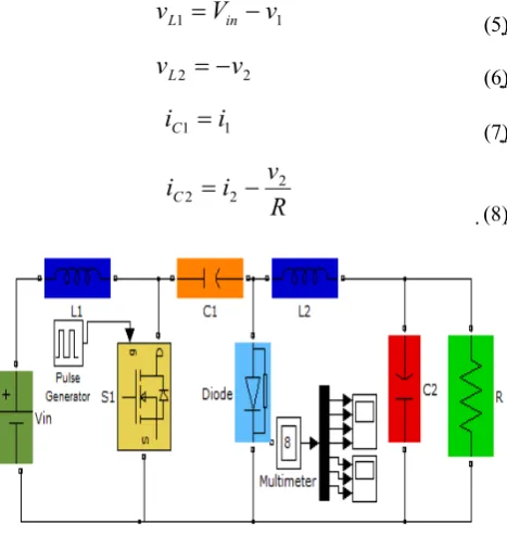
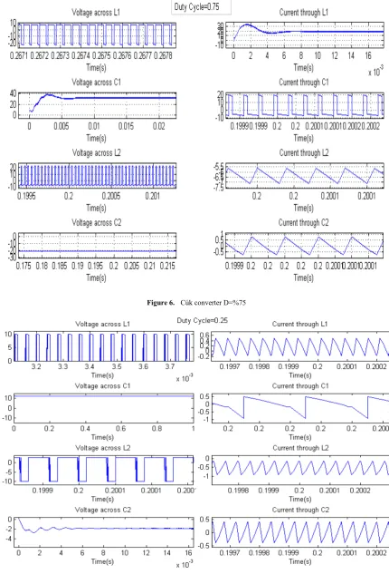
Figure 6. Cúk converter D=%75
3. Permanent Magnet DC Motor
[image:4.595.315.521.76.283.2]A DC motor, armature circuit diagram of the electrical circuit and the mechanical rotor shown in Figure 8.
Figure 8. PMDC motor equivalent circuit.
ω θ θ dt m
d = . = (9)
load m m a m
md m dt K I f M
J ω = .φ. − .ω −
(10)
m b a a
adia dt V R i K
L = − . − .φ.ω
(11) In this model, the engine torque Te, IA armature current, armature construction constant (Kt) by multiplying the (Te = Kt.ia) is obtained. Armature voltage (ea), the rotational speed
(ωm) and motor construction constant (Ke) by multiplying (ea = Ke.ωm) are available. Rotational speed of the motor shaft, the position change over time, sewage, equation (9) is expressed. Mechanical and electrical components of the motor equations, equations (10) and (11) are expressed. Many mathematical method using equations (10) and (11) can be solved [5].
4. Establishment of the System Control
Model
In this study, Cúk converter circuit separately, PI, PID, and is controlled by the FLC. A DC inverter output voltage for a given input voltage, the value of the switch is controlled by setting the duration of the transmission and cutting. In these periods, Pulse Width Modulation (PWM) method is called is set. Fixed switching frequency PWM switching, switch control signal repetitive waveform shown in Figure 9 is obtained by comparing the signal level voltage Vk controls [6-7].
DC inverters, the input voltage and output load are changed, even if the desired average value of the output voltage that is requested. It is designed for different control models. The most important of these is the PI, PID and Fuzzy Logic control. This control models desired, and comparing the actual voltage values are the error and the error change [8]. These two values form input control models. The output of the model is used for switching the PWM control voltage Vk. Control model, the inverter sets the value of the actual output voltage Vk in order to deliver
the desired voltage.
Figure 9. Pulse Width Modulation (PWM)
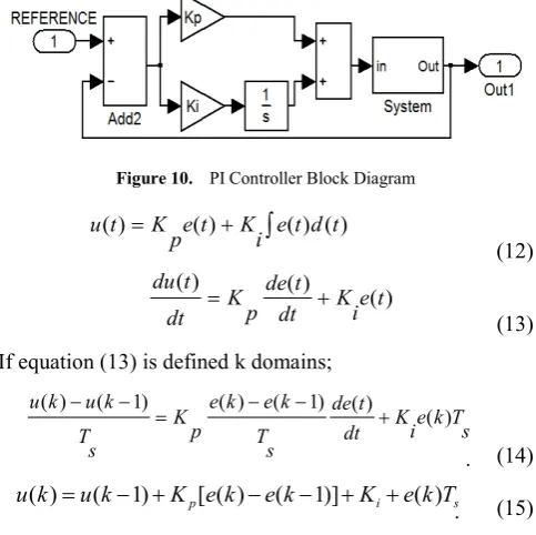
4.1. Proportional Integral (PI) Control Type
The control block diagram of the classical PI controller is given in Figure 10. According to DC converter reference voltage input circuit, output voltage, is controlled by the PI controller. On activated equations are as follows.
Figure 10. PI Controller Block Diagram
∫
+
= () ( ) () )
( e t d t
i K t e p K t u (12) ) ( ) ( ) ( t e i K dt t de p K dt t
du = +
(13) If equation (13) is defined k domains;
s T k e i K dt t de s T k e k e p K s T k u k u ) ( ) ( ) 1 ( ) ( ) 1 ( ) ( + − − = − − (14) s i
p e k e k K e k T
K k
u k
u( )= ( −1)+ [ ( )− ( −1)]+ + ( ) (15)
To obtain the equations for the control circuit. Where Ts is the sampling time is equal.
The coefficients used in the design of conventional PI and PID controllers are shown in Table I.
Table 1. PI and PID Parameters
PI PID
P 0,001 0,001
I 0,02 0,02
[image:4.595.88.289.130.344.2] [image:4.595.312.554.381.622.2]4.1. Fuzzy Logic Control Type
The first is a small steam engine as the control for fuzzy logic control was carried out by Mamdani and Assilian. Fuzzy logic control algorithm consists of a set of rules and linguistic terms to express an intuitive control for fuzzy sets and fuzzy logic to evaluate the rules used [9-10].
[image:5.595.320.543.165.415.2]As is known, the structure of fuzzy logic controller consists of three parts. If you need a brief look at these sections, the first as "The Blur" phase, the absolute values are converted to fuzzy values. Then, fuzzy rules, fuzzy values are processed "Rule processing and decision-making" phase, and finally, "defuzzification" step, the exact result is converted to fuzzy. Fuzzy logic control system is shown in Figure 11[11-12].
Figure 11. FLC Controller Block Diagram
Figure 12. The block diagram of the whole system
5. Simulation of the Entire System
[image:5.595.66.294.273.688.2]Figure 12 PI in the system, in turn, is connected to the PID and FLC. These controllers, variable speed error between the reference and the output signal audited by the Cúk converter is PMDC motor actual speed with PWM method determines the position of the MOSFET switch. Cúk converter, determines the output voltage of the switch position. This voltage determines the speed of the motor.
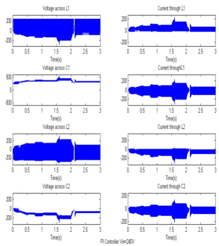
Figure 13. Cúk converter with PI controller components, current and voltage values change over time.
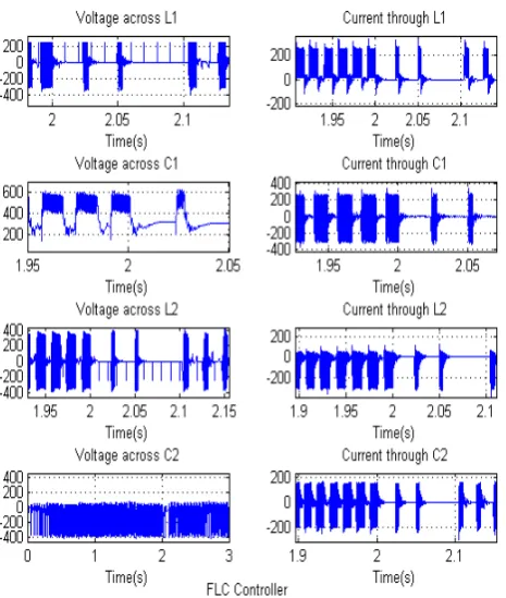
[image:5.595.317.545.458.726.2]Figure 15. Cúk converter with FLC controller components, current and voltage values change over time.
Figure 16. PI Speed
Figure 17. PID Speed
Figure 18. FLC Speed
6. Conclusion
The Fuzzy logic control method can easily be applied Cúk converters. In this study, the voltage applied to the motor to control the speed PMDC must be changed over time, and reduces both can increase the Cúk converter voltage converter types are selected. Converter control conventional PI, PID and Fuzzy Logic control were performed separately.
Designed in MATLAB / Simulink environment, as shown in the graphs obtained from simulated, Fuzzy Logic control, the control strategy and decision-making to be based on a rule base is capable of changing the system due to the conditions under normal conditions and in accordance with the PI and PID control, it is seen that better results. Similar to the PID control, PI control provided by a better dynamic performance.
REFERENCES
[1] Vehbi B., Seta B., Metin G. Paralel aktif filtre
uygulamalarında adaptif bulanık mantık kontrol
yöntemlerinin uygulanması, İTÜ Mühendislik Dergisi, Vol.
4-2, 2005.
[2] K.M.Smedley, C. Slobodan. One-Cycle Control of Switching Converters, IEEE Transactions on Power Electronics, Vol. 10, No.6, 625-634, 1995.
[3] Sefa İ., Altın N., Özdemir Ş. dSPACE Based Fuzzy
Logic Controlled Boost Converter, 4th International Conference on Technicaland Physical Problems of Power Engineering TPE-2008, University of Pitesti, Pitesti, Romania, 2008.
[4] L. Guo, H. Nelms, R.M Nelms. Design and Implementation of Sliding Mode Fuzzy Controllers for a Buck Converter, IEEE International Symposium on Industrial Electronics, 1081-1087, Montreal, Canada, 2006.
[5] Zenk H. and Altaş İ. H. Farklı Kural Tabanlı Bulanık Mantık
[image:6.595.67.321.386.745.2]Performanslarının Kıyaslanması, Otomatik Kontrol Ulusal
Toplantısı, 536-540, Gebze, Kocaeli, 2010.
[6] Akyazi Ö., Sesli E. DA-DA Boost Dönüştürücülerde Çıkış
Gerilimi ve Endüktans Akımının Bulanık Mantık ve Oransal İntegral Denetleyicilerle Karşılaştırılması, 2010.
[7] H.S.Park, Kim H.J. Simultenous control of buck and boost DC-DC converter By Fuzzy Controller, ISIE, 1021- 1025, Pusan, KOREA , 2001.
[8] A. J. Calderon, B. M. Vinagre V. Feliu, Fractional order control strategies for power electronic buck converters, Signal Processing, ELSEVIER, 2803–2819, 2006.
[9] C. Elmas, M.A. Akcayol, T. Yigit. Fuzzy PI Controller For Speed Control of Switched Reluctance Motor, J. Fac. Eng.
Arch. Gazi Univercity, Vol 22, No.1, 65-72, 2007.
[10] M. Sekkeli, C. Yıldız H. R. Özçalık. Bulanık Mantık ve
PI Denetimli DA-DA Konvertör Modellenmesi ve Dinamik
Performans Karsılastırması, K.Mara Sütçü İmam
Üniversitesi, Mühendislik-Mimarlık Fakültesi,
Elektrik-Elektronik Bölümü, K.Maraş, 2010.
[11] H. Zenk, O. Zenk, A. S. Akpinar. Two Different Power Control System Load-Frequency Analysis Using Fuzzy Logic
Controller, INISTA 2011, Dogus University, İstanbul,
Turkey, 2011.
[12] H. Zenk, A.. Akpınar. Multi Zone Power Systems