Journal of Chemical and Pharmaceutical Research, 2014, 6(7):401-408
Research Article
CODEN(USA) : JCPRC5
ISSN : 0975-7384
A dental model segmentation algorithm for Invisalign software
Guang Yang*, Yanfang Yue, Yongdi Zhang, Songhe Wu and Yang Wang
Hebei University of Science and Technology, China
_____________________________________________________________________________________________
ABSTRACT
In order to increase efficiency and accuracy in auto-segmentation of STL dental cast for invisalign, the paper improves the traditional segmentation algorithm. The new algorithm changed single piece input mode into area selection input mode . The bending degree expression about adjacent surfaces was taken as the corresponding height field functions. We designed the direct insertion sort instead of the stack sort. The result shows that the new algorithm can achieve a more complete segmentation for dental crown and improve efficiency, as meets invisalign requirements.
Key words: Segmentation Algorithm; Area Mark; STL Format; Dental Cast
_____________________________________________________________________________________________
INTRODUCTION
Dental Cast is generally converted into the complete STL digital model by 3D scanning[1-2], in the process of orthodontic treatment, only one or a few teeth are required to move or rotate. Therefore, the key problem of Invisalign is to separate the teeth which need move from the complete STL digital model. Summarize current automatic segmentation algorithm following several methods: boundary identification method[3], vector approximation method[4], interactive marker-controlled method[5-6].
The algorithm of boundary identification method is simple and has high efficiency, but the segmentation boundary is relatively rough and not obvious, especially the results of dental crown which are incomplete discouraging. Vector approximation method has the relatively ideal segmentation boundary, however, the results of segmentation often include part of the edge of gingival, are not only the dental crown, so that the algorithm has less efficiency. Interactive marker-controlled segmentation method is a relatively ideal algorithm, obtaining patch by manual as marker, finishing separating by automatic extension. The segmentation boundary is comparatively complete. But this algorithm has a disadvantage. Its seed patch is only a single triangular patch. The local surfaces of one tooth have a plurality of function of flexure, which will not have a complete segmentation results.
The paper improved the traditional segmentation algorithm, proposing a area selection method of segmentation. The new algorithm can achieve a more complete segmentation for dental crown efficiently and accomplish orthodontic treatment. Furthermore, we used MAX Script scripting language on the 3DSMax platform to carry out the secondary development, so that the automatic segmentation of teeth became a reality.
STL DENTAL CAST CHARACTERISTICS
In practice, the STL format model can be obtained by the point cloud processing in Reverse Engineering; also can be obtained by the triangulation of 3D model surface, namely in accordance with the required accuracy using a certain number of triangles to approximate the shape of the model surface. In the latter approach, each triangular patch are represented by the vertex coordinates of the triangle (xi, yi, zi) (i=1, 2, 3) and a normal vector n (on which side of the
(1) Incisor teeth in buccolingual directions are concave, and lip-side is convex. The values of bending function of adjacent two triangles in the dental crown are higher than the values in the edge of gingiva. All above can provide the theoretical foundation for the implementation of this segmentation algorithm.
(2) Local surface of certain dental crowns may be scraggly, particularly the values of bending function of adjacent two triangles in the top of the molars are smaller than the values in the edge of gingiva, therefore using the threshold method is difficult to select all.
(3) There exist various types of individual differences in human teeth, including geometric shapes and dimension, so it has been difficult to carefully macroscopic study on all of the dental cast by a individual model shape.
SEGMENTATION ALGORITHM
At present, Interactive marker-controlled segmentation method[8] is a relatively ideal algorithm, the following is a detailed description of the algorithm.
A. Interactive Marker-Controlled method
The algorithm was put forward on the basis of the watershed algorithm[9-10], using its marker as seed, starting from a seed point, and then completing the segmentation process. Mainly includes three key steps:
(1)Selecting a single patch as marker
In the present study, the input of interactive marker was single triangular patch which used as seed patch. In the single tooth, the bending function values of the local part were smaller than the values of adjacent two triangles in the edge of gingiva[11-12]. If the threshold value (it is an intermediate value that imported through interactive mode and defined by comparing with the adjacent patch bending function values) was smaller, the local part could not be chosen, otherwise the gingival portion was also wrong selection, so a few teeth always were unable to select complete teeth crown.
(2)Calculating bending function of adjacent patches
We established two triangular patches f1 and f2, their unit normal vector were respectively n1 and n2 . As shown in
Fig.1, AC was the public edge, AB was the non-public edge. Therefore, the relative bending function C of patch f1, f2
was:
0
0
2
1
2
1
1 1 2
1
2 1 1
2 2
1
≤
⋅
>
⋅
⋅
−
⋅
−
=
=
AB
n
AB
n
,
n
n
,
n
n
)
,f
C(f
)
,f
C(f
]
1 , 1 [ 2 1,f )∈ −
C(f
When the boundary of the f1 and f2 was concave boundary, C (f1, f2) was negative, and the boundary was convex
boundary, C (f1, f2) was positive, moreover the bending degree function values between the two adjacent were only
related to the angle between them[5].
(3)Segmentation Algorithm
The adjacent patch of the seed patch that got by above A(1) were pressed into the stack, and as the initialization of the stack. Calculating the three relative bending function values C(curvature) of the three adjacent surfaces, then
C(curvature) from big to small realignaed was pushed onto the stack. In this way, the element was positioned at the
top of the stack for the current maximum C (curvature) value, first out stack; the element of the smallest C (curvature)value was positioned at the bottom of the stack, and finally out of the stack. We repeated the above stack operation process, starting from the seed patch, calculating all select qualified and labeling connected patches. The time complexity of this algorithm is much higher.
B. The Improvement of algorithm-Area Selection Algorithm
then selected as the qualified patch, so it was good to avoid some local bending function value was very small and could not be automatic selection problem. Specific principles such as B.(2) segmentation algorithm about. As shown in Fig.1: Fig.A, the single patch was selected as the seed surface segmentation results by marker-controlled interactive method; Fig.B was through the area selection method to choose the segmentation result. From the segmentation results could be seen, area selection method is better than the marker-controlled method.
Figure.A Figure.B
Figure.1 Comparison of single patch and area marker segmentation results.
(2)Optimized Segmentation Algorithm
Area selective segmentation method[12] aimed to pick out the patches which were connected with the markers and met the requirements. By B.(1) to determine the segmentation part, recording the extension process by a queue S.Using S[i] (i=0,1,2,3... ) that was obtained by exchanging as the seed patch, looking for the adjacent patches, the satisfactory and the unselected patches were added directly to the rear. According to the queue serial number as a seed patch, this process would sequentially visit all the patches in the queue, ultimately S[i+n] ( n is for after added patch) was the patch set that meet the requirements. The flow chart of the algorithm is shown in Fig. 2.
Figure.2 The flow chart of Tooth patches
Supposed that R was the set of all patches which need to split, R1 (i=1,2,3... i-1) and R2 (i, i+1, i+2...) was the
Figure.3 The adjacent search of seed segmentation algorithm.
The first step: Insert the seed patch into the queue. According to the ID number (assume ID(1)< ID(2)< ID(3)<...), the seed patches were inserted into S(S=R1+R2)from small to large; The second step: Search for the adjacent patch.
Putting the first element ID(1) of S into V, then, then finding out three adjacent patches of the patch boundary (ID (2),
ID (4), ID (a)), due to the patch ID(2) and ID(4) had been accessed (2, 4 interactive selected in the R2), then a was
the adjacent patch we need; The third step: Determine whether the adjacent patches meet the requirements. By A(2) algorithm to get the patch 1 and a relative bending function value C, compared them with T of interactive input, if
C>T and unselected, then a was directly added to the S (i.e. insert to the tail), seed patch did not delete; If C<T, then
directly went to the next step; The fourth step: Take the next element to segment. To determine whether the rear queue element, is, end, or remove an element and repeat the cycle. In the expansion process of the algorithm, according to the ID, the patches that interactive selected from S were used as seed patches accessed from small to large, then according to insert the queue time visiting the new patches, this process until all the patch of S finished visited, so S[i] was required for qualified patch .
If the initial threshold segmentation model could not obtain satisfactory results, through the interactive input mode adjusted the threshold size, going to resegmentation. In general, the segmented were closed areas, could reach the demand. If there were some local on the teeth boundary, just adjusting threshold was not able to meet user needs , we could add to the selected region through interaction, consequently splited from the parts needed.
RESULTS AND DISCUSSION
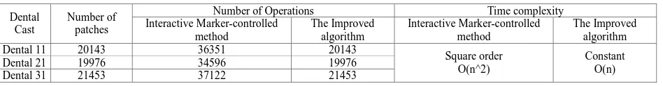
From the operation times of algorithm stack and the segmentation process time required to analyze[7], interactive marker-controlled method put the bending function value into the stack, and the number of stack is equal to the number of the selected area model triangle , area selection method put the patch ID into the queue. Its input-queued number is equal to the number of the selected area model triangle, in the STL model, the number of edges of the triangles is about 1.5 times the surface, so area selection method saves a lot of time in the number of the operation.
In terms of Sorting algorithm, the original algorithm needs to be sorted again when push on, so time complexity is square, however the algorithm based on the threshold to determine whether adjacent patches of triangles meet the requirements, and it is directly inserted into the queue not need sort, the time complexity of the algorithm is a constant, the process speed is improved obviously. Comparison of the two algorithms is shown in table 1.
TABLE I Comparison of the two algorithms
Dental Cast
Number of patches
Number of Operations Time complexity Interactive Marker-controlled
method
The Improved algorithm
Interactive Marker-controlled method
The Improved algorithm Dental 11 20143 36351 20143
Square order O(n^2)
Constant O(n) Dental 21 19976 34596 19976
Dental 31 21453 37122 21453
[image:4.595.72.546.624.686.2]spinner button was the role of interactive input threshold; by clicking the teeth segmentation button, automatically completing the teeth segmentation in 3DSMAX.
In the process of orthodontic treatment, sometimes need to move multiple teeth at the same time. In the algorithm described above, each tooth was separated, multiple teeth could not be simultaneously moved or rotated. The algorithm optimized by us first marked in different teeth at the same time, and then took the segmentation operation, multiple teeth taken together as a group was divided into the designated area, in consequence area selection method was a very good solution to this problem. Segmentation result is shown in Fig.4: A is the situation that two incisor teeth of the dental cast were selected at the same time and moved in the buccolingual dirction; B is the situation that one lateral incisor tooth of the dental cast was selected and moved in the lip dirction. Based on the algorithm the segmentation and movement of the teeth had been completed in 3DSMAX platform, and certain generalizations that segmentation speed and the accuracy completely met the needs of users can be derived from the comparison in Table 1.
Figure A.
Figure B
Figure. 4 The flow chart of Tooth segmentation algorithm.
ARITHMETIC EXAMPLE
The algorithm started from the seed patch, found the adjacent patches, and the patches were compared with the interactive input threshold, if they met the requirements would be selected as seed patch, until all qualified patches were accessed, thus completed the teeth segmentation. Detailed calculation process is as follows[16-18].
(1)Selecting the seed patch
Extracting the normal vector, the sequence number of the three edges, the sequence number of the three vertexes, and the vertex coordinates.
(2)Searching for the adjacent patch
According to the seed patch edges, looking for the two patches which shared its edge, then find the adjacent surface by the sequence number.
(3)Extraction of the information of adjacent patch
Extracting the normal vector, the sequence number of the three edges, the sequence number of the three vertex, and the vertex coordinates.
(4)Calculating the vector
Its starting point in the seed patch, the terminal point in the edge of the adjacent patch .
(5)Using the vector of the edge to dot product the vector of the seed patch, and calculating its value.
(6)Calculating the value of the vector from the adjacent patch to the seed patch. Through the following concrete instances, the question was explained in detail.
number of each edge, each vertex of the four patches, and the value of the vertex coordinates. And then finding out the corresponding related and independent part. As shown in Fig. 5:
Figure.5 The seed patch and adjacent patches
The specific calculation process was as follows:
The first step: Dental cast was converted to editable poly. The code was: convertTo $ Editable_Poly. The second step: Looking for the three vertex coordinates of the patch: polyop.getEdgefaces $ 176509. The third step: Getting the three edges column number of this patch:#(268259, 268260, 268257). The fourth step: Obtaining the coordinate values of the edge No.268259:polyOp.getvert $ 268259. The fifth step:Getting the coordinates sequence number of the two vertices of the edge:#[91520,91521]. The sixth step: Calculating the coordinate values of point 91520: [5.64608,25.0841,-7.68313].
Fig.6 was the specific information of the face, edge, point of the four patches.
Figure. 6 STL triangle patch detailed data
In 3DSMAX, the patch normals could automatically extract, the main program code: polyop.getFaceNormal $ .
[image:6.595.79.532.386.628.2]1
)
670001
.
0
(
717856
.
0
)
189159
.
0
(
−
2+
2+
−
2=
=
n
Then to calculate the edge which in the adjacent patches (ADC) and not with the seed patch common boundary,such as edge AD:
calculation of the vector AD .
]
37695
.
0
,
3373
.
0
,
0451
.
0
[
)]
68313
.
7
(
06008
.
8
,
0841
.
25
7468
.
24
,
64608
.
5
60098
.
5
[
)
,
,
(
−
−
−
=
−
−
−
−
−
=
−
−
−
=
XD
XA
YD
YA
ZD
ZA
AD
. . . . . -. -. -. . -. -AD n 0 5 0189551190 0 5 2525568769 0 2421328288 0 0085310709 0 )] 37695 0 ( ) 670001 0 ( ) 3373 0 ( 717856 0 ) 0451 0 ( 189159 0 [ 1 > = + − = ∗ + ∗ + ∗ = ∗ -0.653358] ,0.746891, [-0.123599 176508 l $ tFaceNorma polyop.gen= =
6335 1.00969182 3358 0.43775051 5696 0.53616018 7281 0.03578112 ) (-0.653358 ) (-0.670001 (0.746891) (0.717856) (0.717856) ) (-0.189159 ) Z Z Y Y X X ( n
n n n n n n n
= + + = ∗ + ∗ + ∗ = ∗ + ∗ + ∗ = ∗ 2 1 2 1 2 1 2 1
31675
0.00484591
n
n
C
=
•
=
−
=
2
1
35
0096918263
.
1
2
2 1Comparing C and the interactive input threshold, if C was greater than the threshold and was not selected before, then treated it as the seed patch to segmentation. In order to achieve expanded selection type of the patches.
RESULTS
The paper proposed a high efficiency segmentation algorithm based on the area selection, the algorithm used the bending degree between adjacent sides as the corresponding height function, starting with the mark of input by the user, selecting all qualified patches, eventually completing the STL model segmentation. The experimental result indicates that, the algorithm does not affect the interactive real-time. User determine the intersected area through the marker and threshold, the same markers are divided into the same area, so the algorithm can meet the needs of practical application. Using this algorithm, the 3DSMAX succeeded to realize the tooth segmentation. In addition to dental cast, the algorithm is also applicable to the STL model boundary search and segmentation of other similar characteristics. The deficiency of the algorithm is that, users are difficult to give a appropriate threshold to get the desired segmentation results, in addition, many complex models still need some necessary user interaction to get the desired results.
Acknowledgments
This work was supported in part by a grant (10113991A) from Shijia Zhuang government.
REFERENCES
[1]Wang Bangkang. Beijing Journal of Stomatology, vol.13, pp. 2-5, 2005.
[2]Zhang Zhengyu, Ding Yucheng, and Hong Jun. Journal of Computer-aided Design & Computer Graphics, vol.06, pp. 1240-1245, 2005.
[3]Hen Youlan, Li Zhanli, and Shi Yupu. Computer Engineering, vol.13, pp. 208-211, 2012. [4]Ji Feng. Journal of Bei Hua University(Natural Science), vol.02, pp. 189-192 , 2008.
[5]Liu Yu. Research on Algorithms in Computer Aided Orthodontic.Chongqing University, 2012.
[6]Li Chengjun, Zhang Chi,Wang Guoping. Fast Marker-Controlled Interactive Mesh Segmentation. Acta
Scientiarum Naturalium Universitatis Pekinensis, vol.42, pp. 662-667, 2006.
[7]Ning Xiaojuan. Research on Segmentation Methods of Dental Digital Model. Xi’an University of Science and Technology, 2007.
[8]Zhang Ch,Zhang Ning,and Li Chengjun. Marker-controlled Perception-based Mesh Segmentation. Proceedings
[9]Guan Huijuan. Study on Region Based Image Segmentation Methods. DaLian University of Technology, 2005. [10]Mangan A,Whitaker R. IEEE. J. Transactions on Visualization and Computer Graphics, vol.4,pp. 308-321,
1999.
[11]Xiong Fusong. The Research of Image Segmentation Method Based on Threshold Selection. Jiang Nan University, 2007.
[12]Quan Hongyan, Zhang Tianwen. Journal of Computer-aided Desing & Computer Graphics,vol. 07,pp. 1011-1016 , 2006.
[13]Geng Jianpu, Cui Hongbin, Liu Qinghua et.al. Hebei Journal of Industrial Science and Technology, vol. 03,pp.50-53, 2013.
[14]Yuan Jianwei,Li Aiguo,and Li Wenyu. Hebei Journal of Industrial Science and Technology,vol. 01,pp. 39-41+46 , 2013.
[15]Huang Xinyuan. Advanced Programming of 3DS MAX, BeingJing, Publishing House of Tsinghua University,
2004.
[16]Jian-Hua Li, Yi-Wen Wang, and Yi Chen et.al. Journal of Computer, vol 8, No 10, pp. 2461-2468, 2013. [17]Jianfeng Li, Beiji Zou, and Lei Ding, et.al. Journal of Computer, vol 8, No 9, pp.2421-2428,2013.