Journal of Chemical and Pharmaceutical Research, 2015, 7(3):1280-1286
Research Article
CODEN(USA) : JCPRC5ISSN : 0975-7384Design and development of an Omni-directional mobile automatic guided
logistics platform with robotic arm
Gao Zhen-Qing, Yang Yuan-xin and Du Yan-ping
Beijing Institute of Graphic Communication, China
_____________________________________________________________________________________________
ABSTRACT
In view of the common logistics robot and vehicle is difficult to adapt to the complex and changeable requirements of modern logistics environment, the respective advantages of omni-directional mobile mechanism and robotic arm used in the traditional logistics are combined to design and develop an omni-directional mobile automatic guided logistics platform with a robotic arm. In this research, detailed structure of omni-directional mobile mechanism and the robotic arm for the platform is designed. Software and hardware of federated control system for the operation of omni-directional movement, automatic guiding and action of robotic arm in the platform are built with the PLC and touch screen as the core. Subsequently, the system control logic was explained and the physical prototype was developed. Finally, an experimental study was carried out in logistics engineering laboratory of Beijing Institute of
Graphic Communication (BIGC). The research improved the flexibility of
logistics transmission equipment, increase the operational efficiency of logistics system and intelligent degree. It has a certain value for the related research for the application field of the mobile robot and logistics equipment field.
Key words: Omni-directional; Automatic Guided; Logistics Platform; Robotic Arm.
_____________________________________________________________________________________________
INTRODUCTION
In some cramped space, uneven pavement, andchangeableenvironment, the occasionsvehicle change frequently, how to quickly complete the task for logistics vehicles, not only can satisfy the working environment and achieve the objectives, but also can show
1281
strategy in which three different reactive behaviors are fused in a single control law by means of a fuzzy supervisor guaranteeing robot safety and task accomplishment[11]. About robots in logistics, Cosma discussed some issues including the design andintegration of mechanical elements, the development of non invasive localization and guidance procedures, the design and control of grasping devices for specific box/storage combinations, and the development of testing, verification and validation procedures satisfying strict pharmaceutical regulations[12]. Li analyzed the feasibility of improving AGV to meet the requirements of field environment and operation standard of substation, and then the design scheme of AGV based robot system used in substation equipment inspection is brought forward[13].
Meanwhile, logistics handling robot is an unmanned automated handling car with non-contact control-oriented devices, based on the battery as a power source, which is widely used in logistics systems to realize cargo transport function[14].Related technologies have conducted in-depth research and have made significant achievements indomestic and foreign, such as vehicle control, path planning, computer control and principle, systems simulation, information acquisition and processing, navigation, auto-recharge, wireless communications, etc[15-20]. The automatic guided logistics platform with a robotic arm, in the development of this Institute, is drawing on experience already. It adopts PLC and touch screen as the core to achieve joint control of the main body of the platform and the robotic arm, more than, sensing technology was adopted in order to realize the platform motion guidance, location identification, obstacle monitoring and robotic arm driven by material gripper positioning. In harsh industrial environments, PLC and touch screen has obvious advantages than computer control system in the stability andanti-interference, moreover, it has superiority like flexible structure, high quality of data transmission, simple programming, strong and durable and saving space[21]. Combining the use of the touch screen and PLC, simplifies the site operation, and improve the flexibility of the control program and human-computer interface, it makes the system more safe and reliable performance[22]. While, currently using PLC and touch screen on AGV research is always very rare[23].
In this paper, an omni-directional mobile automatic guided logistics platform with robotic arm was developed. It combined omni-directional movement, automatic guidance, materials grabbing. In the following, mechanical structure for the platform, hardware and operation logic was designed, the prototype was developed. Finally, the validity of the study was proved through an experiment.
DESIGN OF MECHANICAL STRUCTURE FOR THE PLATFORM
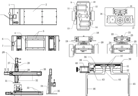
The overall mechanical structure of platform includes four parts: the main body of the platform, drive unit, robotic arm, and tray gripper, as showed in Fig.1. It can realize omni-directional movement through the suspension drive unit in the bottom of main body. It can grab and put plastic tray with standard size through robotic arm and tray gripper mounted on main body. The function of magnetic navigation sensor is automatic guidance.
The main body of the platform mainly plays a role as supporting, is used to install the driver unit, robotic arm, tray gripper and control unit. Body shell is equipped with touch screen(1), emergency stop button and reset button(2), obstacle sensors(6) and four universal casters(8). In addition, four universal casters are the driven wheel, that ensure the platform can complete the omni-directional mobile body, realize the movement of the vertical and horizontal without turning the platform.
Fig. 1: Mechanical structure of theplatform
The robotic arm is arranged on the top of main body, achieves two direction moving of the tray gripper through two sets of slide guide, and that, the third direction position of the tray gripper is controlled by the main body’s motion under the thumb of the landmark sensor.Thus,the tray gripper can move in a three-dimensional space and the location is identified by a proximity sensor to ensure the accuracy of material grasping motion.
Tray gripper uses the structure of screw slide, wherein two sections of the screw (39) are designed to different rotation direction. It is controlled by a stepper motor to achieve two gripper clamping piece(45) backward movement, completes movement of clamping and opening, thus the customary size tray can realize the movements as capture, transfer and placement.
The control unit of the platform is installed in the main body. Itis simple so that the structure isn’t analyzed in this paper.
HARDWARE FRAMEWORK OF THE PLATFORM CONTROL SYSTEM
Hardware framework of the platform control system includes touch screen, PLC, orientation sensor, landmark sensor, obstacles sensor, motor drive, proximity sensor and electric part, its principle block diagram is illustrated in Fig.2.
PLC
电机驱动器
车体电机
车体
机械臂电机
机械臂
触摸屏
(1) The main part of the Platform
(2) Drive Unit
(3) Robotic Arm (4) Tray Gripper
1-Touch Screen; 2-Upper Cover Plate;3-Emergency Stop and Reset;4-Supporting PlateX2;5-PlatformMain BracketX4;6-Obstacle SensorX2; 7-Caster Mounting PlateX2;8-Universal CasterX4;9-Driving SprocketX2;10-Axis Beam Fixed SeatX2;11-Steering ShaftX2;12-Driven
Sprocket; 13-Sprocket BearingX4;14-DC MotorX2;15-Damping CrossConnectionX4;16-Shock Fixed
Plate;17-Magnetic Navigation SensorX2;18-Body Connecting Plate; 19-Limit BlockX2;20-Driving WheelX2; 21- Damping SpringX2;22-Shock Mounting PlateX2; 23-Spring ColumnX2;24-Support ColumnX2;25-Thrust Ball Bearing;26-Stepper Motor;
27-Coupling;28-Bearing Fixed Seat; 29-Sensor;30-AluminumAlloy Clip HandX2;31-Mounting
Plate;32-Aluminum Alloy CantileverX2;33-Guide Rail and Slide Block X2; 34-Reinforcement;35-Base Fixing Plate; 36-Mounting Plate; 37-Guide Rail Sliding Block;38- Motor Mounting Plate; 39-Screw;40-Stepper Motor; 41-Acrylic Cover;42-Bearing Fixed Seat;
[image:3.595.79.534.78.394.2] [image:3.595.288.526.588.820.2]
1283
As shown in figure2, touch screenand PLC is the control core of the platform, which can control the DC drive motor of the main body and stepper drive motor of robotic arm, also receive real-time information about related sensor to finish the closed-loop control.
In the course of development, electromagnetic sensor is used for the guidance along the metal line laid under the ground. Magnetic induction sensor is applicable to the obstacle sensor in order to avoid the collision of unexpected obstacles in the track. Similarly landmark sensors also use the magnetic induction sensor that installed in the work station for identification of different station. Moreover, proximity sensor employs a photoelectric sensor to guarantee the manipulator capture process can reach the accurate position and assume that the tray can complete the move of pick and place. Sensors, introduced above, realize the real-time information exchange with PLC. According to the feedback information from sensors, the movement of drive motors can be controlled, which ensurethat the main body and the robot arm to complete the necessary actions in accordance with mission requirements.
SOFTWARE OPERATION LOGIC OF THE PLATFORM CONTROL SYSTEM
The hardware system of the platform is under the control by software of PLC and touch screen, which can work together to accomplish the task assigned. The process of its operation logic of the platform control system is generally shown in Fig.3.
According to the process in figure 3, the corresponding program was organized and input to the PLC and touch screen. Consequently, program can run automatically after power supply, then two subdivided driving wheel of the drive unit can rotate in the same direction and speed, the platform can move along the guideline. When the motion of the platform meets the turning track, the platform will stop motion, and then two driving wheels rotate in reverse direction and uniform speed that makes the drive unit change its orientation in the occasion that the main body doesn’t move. When the route direction of turning is consistent with the direction of the driving wheel, the driving wheel will stop rotating and restore the rotation in the same direction and speed, so that the main body can move along the original direction.
In the process of movement, the platform identifies its position with landmark sensor according to the task requirements and procedures. When the indication detects the correct information, platform will stop in the corresponding work station. Later, horizontal and vertical axes in the mechanical arm move to the corresponding position by the proximity
sensor. Getting to the designated position, the tray gripper achieves the action of grabbing or placing, and resets after the completion of the operation. A cyclic executive above logic, until the program is finished, the task is completed, platform automatically moves back. It is required that mobile order above the longitudinal movement and transverse movement is analogous to the motion of the tray from the
station to the platform. On the contrary, the vertical axis moves in the former. In addition, for whatever state, triggering the obstacle sensor, platform immediately stops running as long as detecting the obstacle.
PROTOTYPE DEVELOPMENT OF THE PLATFORM AND EXPERIMENT RESEARCH
According to the above design about mechanical structure, hardware framework and software logic, the physical prototype was developed and its 3D model as showed in Fig.4. The figure marks the general composition unit, and the platform is running well at present.
For proving the research, an experiment was carried out in a logistics system layout is shown in figure5. This system locates in logistics engineering laboratory of Beijing Institute of Graphic Communication (BIGC), which includes four production lines, 1 set of an omni-directional mobile automatic guided logistics platform with robotic arm and metal line for guidance and a storage shelves. In the four production lines, two 3D print productions, one for ink jet printing and one for laser printing.
In Fig.5, the following code meaning:
WS1: Work Station 1, 3D Printing; WS2: Work Station 2, 3D Printing; WS3: Work Station 3, Ink Jet Printing; WS4: Work Station 4, Laser Printing; PM1/PM2: Package Machine 1/2; BM1: Binding Machine 1; BM2: Binding Machine 2; CM1-CM4: Coding Machine 1-4;
PM-I/PM-II: Package Machine I, Packaging finally, different with PM1 and PM2;
Platform: Omni-directional Mobile Automatic Guided Logistics Platform with Robotic Arm.
In this system, the transmission process of finished product from PM-I/PM-II to Storage Shelves is relatively stable, and the route is fixed, so Platform is used to complete this task easily. But, at the same time in the system operation process of four production lines, there may be abnormal phenomena, such as:
i) After printed in WS3 or WS4, the printing need not to be bound, but need for packaging, then code. In this case, the printing is transferred from WS3 or WS4 to PM1 or PM2, and then sent back to the code position CM3 or CM4 of original packaging production line.
1285
ii) The bound printings is coded after package, the printings in BM1 or BM2 will be transfer to PM1 or PM2, and then sent back to the code position CM3 or CM4 of original packaging production line.
iii) If the printings waiting for coded in one of PM1, PM2, BM1 and BM2 overstock, it will be transferred to the code machine in other free positions, then returned to the PM-I or PM-II of original production after coding.
iv) If the printings are overstocked in CM1-CM4, it will be transferred to other packaging machine PM-I or PM-II.
Theabovesituation, requirements in transmission between each production line, it is difficult to meet the requirements for common equipment. So, the flexible platform needs to be used in the above conditions. The platform in this system adopts automatic guided electromagnetic device and run along the metal line underground.
CONCLUSION
Omni-directional mobile automatic guided logistics platform with robotic arm has many advantages: sorting the material handling time greatly, saving working space, improving work efficiency, improving the logistics system's automation and intellectualization. There are beneficial to in-depth study of the problem. On the one hand, the research can be expanded in some aspects, suchas path planning, motion flexibility, analysis of the tray's work space, thereby extending the applicability of the platform. On the other hand, the relationship among work environment, tasks and the platform should be studied to build the calculation model and improve the overall performance of logistics system.
Acknowledgments
The authors wish to thank the Scientific Research Project of Beijing Educational Committee (KM201510015007), under which the present work was possible.
REFERENCES
[1]Paskaleva K. International Journal of Innovation and Regional Development, v.1, n.4, pp.405-422, 25 January, 2009.
[2]AroraA..Traffic Engineering and Control, v 53, n 10, p 375-378, November 2012.
[3]B. Chen and H. H. Cheng. IEEE Trans. Intelligent Transportation Systems, vol.11, no.2, pp.485–497, 2010. [4]SengDewen. Applied Mechanics and Materials, v. 189, p. 482-485, 2012.
[5]SENG Dewen, LI Zhongxue. Journal of Liaoning Technical University, Vol.27(1), pp.9-12, 2008.02. [6]Dikaiakos M. D..Minersoft: ACM Transactions on Internet Technology, v.12, n.1, June 2012. [7]SengDewen, ShuYueqing. Advances in Intelligent Systems and Computing, p. 393-400, 2013. [8]Di Lecce, V. Amato, A. IET Intelligent Transport Systems, v 5, n 3, p 149-158, September 2011.
[9]Prashant T., Kavita D., Manish S..International Journal of Soft Computing and Engineering, v.2, July 2012. [10]LIN T. Y. Granular Computing: From Rough Sets and Neighborhood Systems to Information Granulation and Computing in Words. European Congress on Intelligent Techniques and Soft Computing, Heidelberg, Germany, pp.1602-1606, September 8-12, 1997.
[11]PANG Ming. Logistics Technology, Vol.7, p190-192, 2011.
[12]LU Weiwen. The Structure Analysis and Design of Omni-directional Mobile Robot.Southeast University, 2006. [13]R. Siegwart, I. R. Nourbakhsh, D. Scaramuzza. Introduction to Autonomous Mobile Robots, 2nd.Massachusetts Institute of Technology, 2011.
[14]CUI Mingyue, SUN Dihua. Control and Decision, Vol.5,p664-670, 2013.
[15]Park B S, Yoo S J, Park J B, et al. IEEE Trans on Control System Technology, Vol.17, p207-214, 2009. [16]Hou Z G, Zou A M, Cheng L, et al. IEEE Trans on Control Systems Technology, Vol.17, p803-815, 2009. [17]Howard T, Pivtoraiko M, Knepper R, Kelly A. Robotics & Automation Magazine, IEEE, vol. 21, no. 1, p 64–73, 2014.
[18]Das T, Kar I N. IEEE Trans on Control SystemTechnology, Vol. 21, p501-510,2006. [19]Wang D, Low C B. IEEE Transaction on Robotics, Vol. 24, p676-687,2008.
[20]Gonzalez R, Fiacchini M, Alamo T, et al. Adaptive control for a mobile robot under slip conditions using an LMIbased approach[C]. Proc of the European Control Conf,p23-26, 2009.
[21]Cupertino F, Giordano V, Naso D, Delfine L. Robotics & Automation Magazine, IEEE, Vol. 13, no. 4, p74-81, 2006.
[22]Cosma C, Confente M, Governo M, Fiorini P. Intelligent Robots and Systems, 2004,Vol.3, p3003-3008, 2004. [23]Li Shengfang, HouXingzhe. Power System Technology, p1-4, 2006.
[24]ZHANG Zheng-yi. Logistics & Material Handling, Vol.7, p67-73, 2005.
[26]ZHANG Han-bin. The Research of Logistics Transport Vehicle for E-Commerce Distribution Center [D]. BEIJING: Beijing Wuzi University, 2014.
[27]YANG Wei,QIU Xiao-hong,FU Wei-ping,LV Jun-ling. Machinery Design & Manufacture,Vol.10, p233-235, 2011.
[28]XU Huan,LIU Qiao,CHE Fei,YUAN Ming. Logistics Sci-Tech, Vol.6, p80-82, 2013.
[29]WU Wei-tao. The Overall Scheme and Key Technology Research of Logistic Transportation AGV [D]. SHEN YANG: Shenyang Ligong University, 2013.
[30]M.A.Shalaby, ed. The International Journal of Advanced Manufacturing Technology, Vol.30, p175-187, 2005. [31]ZHOU Jian-min, ZHOU Qi-xian, XU dong-dong. Instrument Technique and Sensor, Vol.2, p103-105, 2010. [32]CHEN Chao-ze, REN De-jun, HE Hua. Instrument Technique and Sensor, Vol.7, p78-80, 2008.