Doctoral Dissertation
Experimental study on motion control of
dual-arm full/semi-autonomous underwater robots
Radzi Bin Ambar
(Student Number: 12584204)
Supervisor: Associate Professor Dr. Shinichi Sagara
Department of Mechanical and Control Engineering
Graduate School of Engineering
Kyushu Institute of Technology
Contents
1 Introduction 1
1.1 Research overview . . . 1
1.1.1 The significant contributions of underwater robots . . . 1
1.1.2 Research and development on underwater robots . . . 4
1.2 Underwater vehicle-manipulator system . . . 5
1.2.1 Autonomous control methods . . . 5
1.2.2 Master-slave system . . . 9
1.3 Problem statements . . . 12
1.4 Objectives of the study . . . 13
1.5 Outline of research . . . 14
2 Resolved acceleration control (RAC) method for underwater vehicle-manipulator systems 16 2.1 Introduction . . . 16
2.2 Modeling of a UVMS . . . 16
2.2.1 Kinematic equation . . . 19
2.2.2 Momentum equation . . . 22
2.2.3 Drag forces and buoyant forces . . . 24
2.2.4 Equation of motion . . . 26
2.3 Resolved acceleration control method . . . 28
3 Experiment on a 2-link dual-arm UVMS using RAC method 32 3.1 Introduction . . . 32
3.2 Dual-arm UVMS . . . 32
3.3 Structure of the 2-link dual-arm . . . 35
3.4 RAC method for a 2-link dual-arm UVMS . . . 38
3.5 Experimental setup . . . 40
3.6 Experimental conditions . . . 41
3.8 Conclusions . . . 44
4 Experiment on a 3-link dual-arm UVMS using RAC method 50 4.1 Introduction . . . 50
4.2 Structure of the 3-link dual-arm . . . 53
4.2.1 Mechanical design of the joint . . . 53
4.2.2 Joint actuator . . . 54
4.3 RAC method for a 3-link dual-arm UVMS . . . 56
4.4 Experimental setup . . . 58
4.5 Experimental conditions . . . 59
4.5.1 Case 1: Moving both end-tips to the desired positions . . . 59
4.5.2 Case 2: Moving right end-tip to a desired position, while main-taining left arm initial position . . . 61
4.6 Experimental results and discussions . . . 63
4.7 Conclusions . . . 65
5 Master-slave system for a 3-link dual-arm UVMS 84 5.1 Introduction . . . 84
5.2 Master controller . . . 86
5.2.1 Robot base main master controller . . . 86
5.2.2 Manipulator master controller . . . 91
5.2.3 Robot base sub-master controller . . . 91
5.2.4 Control system . . . 101
5.3 Experimental setup and conditions . . . 102
5.4 Experimental results and discussions . . . 103
5.5 Conclusions . . . 104
6 Conclusions and future recommendations 110
Acknowledgement 112
Chapter 1
Introduction
1.1
Research overview
1.1.1
The significant contributions of underwater robots
It is unquestionable that two most exciting and intriguing exploration of this century are space and ocean. “Space: the final frontier” is a phrase from the 1960’s televi-sion movie called Star Trek, portraying the effort of humanity exploring deep space hoping to meet other life forms and civilization [1]. The phrase became popular in the early stages of space exploration race, between the United States of America and Soviet Union. Since the Soviet successfully launched the first artificial satel-lite Sputnik 1 into the orbit in 1957, tremendous efforts involving money, time and exposure have been put forward towards the space-age exploration. But, only few knew that ocean exploration have been done by humans for thousands of years ago. Undocumented facts suggested that ocean exploration started around 4500 B.C. in coastal cultures such as in Greece and China. Human began diving into the sea as a source for food gathering and commerce. While in between 1519 to 1522, Ferdinand Magellan’s ship explored the surface of the ocean by being the first to circumnavigate the world [2]. On 23rd January 1960, oceanographer Jacques Piccard and Lt. Don Walsh of United States Navy explored to the deepest part of the Earth’s ocean. Both were the only crew inside a submersible vehicle called Trieste, the first manned or unmanned vessel to reach the deepest point of Challenger Deep in the Mariana Trench, believed to be the deepest point of the sea at a depth of 10,916[m] [3]. Though, despite these achievements, hundred of millions of dollars are still being spent in high-tech earth based telescope, designing space rocket thrusters and sending space probes for studying planets and beyond our solar system.
of exploring new world that still never been seen by human. Water covers 71% of Earth surface [4–6]. To be more specific, 96.5% of Earth’s water can be found in the ocean [6]. Ocean covers a large of the earth, which is relatively less explored. Until recently, to discover the secret in the depth of the sea seems impossible. Further-more, ocean exploratory activities involving manned underwater vehicle exposed the operator to extreme conditions which may be dangerous such as underwater pressure, visual visibility and oxygen supply problems. These problems have been resolved by underwater vehicle involving robotic manipulator technology.
Underwater vehicles have been heavily involved in various underwater activities especially related to intervention tasks [7–11]. Many of these robots utilized master-slave system where human operators remotely controlling the motions of underwater vehicles and robotic manipulators using controllers from the surface. Since the technology of fully autonomous underwater vehicles for intervention tasks are still in research and developing stages, master-slave control of underwater robots are still the most relevant today. Underwater robots have been utilized in various fields such as scientific explorations, oceans construction, oil and gas explorations, military and even search and rescue operations.
On 12th August 2000, Russian submarine K-141 Kursk sank into the bottom of the Barents Sea after an explosion of one of its torpedo, resulting to the catastrophic second detonation of further torpedoes. With no capability of rescuing on this type of disaster and the delay of accepting aid from other countries by the Russian govern-ment resulting to the death of 23 crews who actually remained alive and trapped in one of the submarine’s compartment. Remotely operated vehicles (ROVs), Sea Owl and SCV 006 assisted human divers to inspect signs of life on board the submarine using high-tech cameras and powerful underwater torch [7]. However, the deploy-ment of these vehicles to assist the rescue mission was far too late. Another Russian mini-submarine called AS-28 Priz get caught on nets and antenna cables off the Kamchatka Peninsula in Russia. Seven Russian sailors trapped inside the subma-rine were rescued using a British remotely-controlled ROV called Scorpio 45 [12,13]. The single-manipulator arm equipped ROV sliced through nets that entangled the submarine, and freed the sailors. Since then, the Russian have been busy preparing the navy fleet with underwater vehicle technology [14, 15]. Whereas, the United States navy have gone further steps, recognizing the high impact of underwater vehicle technology by developing underwater spy robot for military purposes [16].
3-dimensional maps of sea-ice draft for ten floes (large floating ice), near coastal regions of the Weddel, Bellingshausen and Wilkes Land sectors of Antarctica. The mean drafts thickness ranged from 1.4 to 5.5[m], with the thickest draft measuring 16[m], and an average of 76 percent of the ice volume showed deformity.
In the Deepwater Horizon oil spill tragedy in the Gulf of Mexico, about a dozen of tethered ROVs were utilized to contain the oil spill successfully [9]. Deep Horizon was a deepwater semi-submersible mobile oil platform that was capable to operate in waters up to 2,400[m] deep, and maximum drill depth of 9,100[m]. The tragedy that killed 11 workers was caused by an explosion of the offshore oil platform that eventually sinking the platform and causing the largest marine oil spill in history. ROVs equipped with robotic manipulators were used to saw off the platform’s busted pipe and positioned a four-story dome over the oil well, and installed a smaller oil-collecting cap in its place to seal off the oil from gushing out of the drill pipe [18]. On July 15, 2010, the flow of oil was stopped for the first time in 86 days [9].
A HUGIN 3000 AUV and Oceaneering Millennium VI ROV were used for archae-ological and historically related work to investigate a sunken shipwreck SS Robert E. Lee and a Russian submarine U-166 in the Gulf of Mexico [10, 19]. In 2001, the untethered HUGGIN AUV surveyed a 2-mile by 1.5-mile of underwater area and detected the shipwreck SS Robert E. Lee and U-166 using sonar and multi-beam bathymetry images. The tethered Millennium ROV was used to visually confirmed the findings. U-boats such as U-166 were sent by Germany’s Hitler during World War 2 to destroy petroleum and merchant related ships. U-166 was the only of such submarine destroyed in the gulf of Mexico. On the hand, SS Robert E. Lee was the last ship destroyed by the U-166. Due to the use of underwater robotics in the surveys and verifications, one of the most fascinating historical finds of World War 2 was solved.
and became an essential part of researchers and related works [21–25]. Based on these examples, the various types of underwater robots that are built for various specialized missions will be explained in the next section.
1.1.2
Research and development on underwater robots
Generally, underwater vehicles can be classified into Manned Underwater Vehicles (MUVs) and Unmanned Underwater Vehicles (UUVs) [26, 40].
According to Blidberg [26], MUVs can be further classified into military sub-marines and non-military subsub-marines. There are various types and classes of military submarines operated by navies around the world. These submarines are usually mas-sive in term of size and can occupy large number of crew. Non-military submarines are usually allow small number of crew due to its smaller size. Usually non-military submarines are utilized for underwater scientific missions such as sub-sea biological communities observations and sample collections. These type of submarines are also equipped with various sensors and robotic manipulators.
Twin Burgers from the University of Tokyo [39]. Many more AUV models can be found in [41] and [42].
ROVs and AUVs that are equipped with a single or multiple robotic manipu-lators are usually called Underwater Vehicle-Manipulator System (UVMS). These manipulators are essential especially for underwater intervention missions.
1.2
Underwater vehicle-manipulator system
1.2.1
Autonomous control methods
Since the 1990s, there are very few research studies related to underwater vehi-cles equipped with manipulators due to various problems [42]. However, a major common problem is the control of the UVMS due to the external disturbances (hy-drodynamic effects), kinematic redundancy of UVMS, dynamic coupling forces be-tween the underwater vehicle and manipulators and gravity forces which can affect the trajectory performances of the manipulator’s end-tips. The movement or buoy-ancy created from the motion of the manipulators also can affect the overall vehicle control performance.
To design an effective control system, it is important to design a robust, stable and precise coordinated motions control between the underwater vehicle and ma-nipulators. There are very few studies on control method for coordinated motion control of the vehicle and manipulator. Furthermore, nearly all of these studies utilized numerical simulations to verify the effectiveness of the proposed methods.
a novel two-layered sliding mode method containing adjustable PID gains and un-known vector estimator have been proposed. They demonstrated that the proposed method effectively controls UVMS through robust control which is insensitive to inaccuracies in the dynamic model of the UVMS through simulations. However, the stability of the sliding control system is a concerned because usually high gain is chosen in order to achieve system stability. In turn, high gain leads to high frequency chattering effect and excites unmodelled dynamics of UVMS.
It is also important to design a control system for the UVMS which can self-tune itself to adapt to changes in the dynamics of the robot and its surrounding envi-ronment which in turn provide a fast responsive performance of manipulator. This method of self-tuning is called adaptive control method. One of the early studies on adaptive control method for UVMS was done by Mahesh et al. [46]. They proposed an adaptive controller for the whole UVMS system by considering both underwater vehicle and manipulator as a single unit. The effectiveness of the controller required a discrete-time approximation of the nonlinear UVMS dynamic and rely on the ability of the controller to adapt to the alternating hydrodynamic coefficients. The performance of the controller has been demonstrated through numerical simulation. The study was followed by Sarkar et al. [47], where a non-regressor based adaptive control is introduced based on bound estimation method for a coordinated motions of a 6-DOF spherical-shaped vehicle with a 3-DOF planar manipulator. The tra-jectory planning was coordinated and centralized but the control was decentralized and separate for each system (vehicle and manipulator). The developed controller does not require prior knowledge of the system except numbers of joints and actu-ator inputs of the system. Antonelli et al. [48] proposed a novel adaptive controller based on virtual decomposition of the manipulator’s links and the vehicle resulting to a modular structure of controller. The modular structure simplifies the system by reducing the computational burden by using a reduced-order regressor by tak-ing into account thruster dynamics and unknown ocean currents. The effectiveness of the proposed controller was demonstrated through numerical simulations on a 6-DOF underwater vehicle equipped with 6-DOF manipulator. In a more recent study, Mohan and Kim [49] presented an indirect adaptive control method based on extended Kalman Filter (EKF) for a 6-DOF underwater vehicle and a 3-DOF manipulator. Payload and disturbance compensation were used to compensate the reaction effects during manipulation tasks.
6-DOF manipulator. A fault-tolerant fuzzy-based redundancy resolution method to distribute the human pilot end-effector command over a ROV with a 4-DOF ma-nipulator was proposed in [51]. The fault-tolerant property demonstrated several advantages such as that it can be use to tolerate faulty joints and impose dynamic joint-velocity constraints for better control of the UVMS. Using numerical simu-lations, they demonstrated that detailed spatial end-effector motions can be com-pleted in real-time through coordination between ROV and manipulator with the fault-tolerant capacity.
In addition the the above studies, several other researchers proposed various control method for UVMS that incorporate hydrodynamic effects into the system. McMillan et al. [52] developed an efficient dynamic simulation based on O(N) algo-rithm (N is the number of links) for a UUV with a robotic manipulator taking into account of hydrodynamic forces. A dynamic equations for an underwater vehicle with an n-axis robot arm was introduced based on Kane’s method by considering external hydrodynamic forces such as added mass, profile drag, fluid acceleration and buoyancy [53]. There was also a unique study on coordinated motions of an underwater vehicle and multiple arms presented in [54]. Mukherjee and Nakamura proposed inverse kinematics and dynamics of an underwater vehicle based on the formulation of of inverse dynamics for space robots in the presence of external gen-eralized forces [55]. Simulation results showed that precise position control of the end-tip of a single main arm was achieved by using two units of stabilizing arms as paddles to counter the forces and moment existed on the shoulder of the main arm, and disturbances acting on the vehicle.
imped-ing the control performance of the end-effector. Recently, [59] proposed an inverse dynamic control method by assigning separate task for the end-effector and vehi-cle. The proposed method considered external hydrodynamic effects and thruster dynamics into the control system. State feedback linearization method is used to solve the non-linearities of the UVMS’s dynamic.
All of the studies explained above are based on numerical simulation. Only a few number of studies that were able to verify their proposed coordinated motion control methods for UVMS through experimental results using actual vehicle. The following research studies are based on experimental studies using actual UVMS.
One of the most significant studies was done by McLain et al. [60], where they de-veloped a coordinated-control scheme for UVMS and provided the first experimental results to verify the coordinated motion control using an actual underwater vehi-cle called OTTER mounted with a single-link arm. The experiments demonstrated that hydrodynamic coupling forces between the underwater vehicle and single arm are the major reason in disrupting the stability of the UVMS during manipulation task. They reported that substantial performance improvements can be realized by incorporating model-based information about the hydrodynamic coupling into the control of the system. The model-based approach contains highly accurate model of the arm and vehicle hydrodynamic interaction forces. Based on the experimental results, good station-keeping capability has been achieved and significant reduction of errors and settling times of the end-tip.
the authors are aware of.
Basically, in literature related to the design of control system for coordinated motions of underwater vehicle and manipulator, there are many more studies that verified the results through extensive numerical simulations compared to experiment-oriented studies using actual UVMSs. Furthermore, although majority of the control methods considered hydrodynamic effects acting on the UVMSs, nearly all of these studies utilized only a single manipulator except for the work done in [54]. This is easily understood because researchers need to address additional external forces problems related to multiple manipulators such as hydrodynamic forces due to added mass and moment, restoring forces due to gravity and buoyancy and hydrodynamic damping [63]. Therefore, it would be interesting to see how a control method per-forms with actual underwater vehicle equipped with multiple manipulators.
1.2.2
Master-slave system
Underwater robotic technologies allow humans to execute intervention tasks in an efficient and safe way by reducing the risks fatalities and injuries during underwater operations. Underwater intervention capabilities using robotic arms are necessary to execute tasks such as valve manipulation in oil and gas related operations; con-ducting science experiments or collection of rocks and marine organisms; and maybe can be deployed for deep-sea search and rescue operation.
robotic system. Thus, semi-AUVs are highly suitable for underwater intervention tasks especially for underwater vehicles attached with multiple robotic arms for object manipulation task.
One of the main component in a master-slave system is the master controller. The master controller is an interface device that sends and possibly receives signals from a control system used, to move a slave robot that includes manipulators [64]. There are various type of master controller such as rate control, position control and force feedback control [40, 65]. Master controllers design based on rate control are commonly utilizing joystick, switches or buttons [66, 67]. On the other hand, position control is usually implemented in the design of manipulator master con-trollers where it requires the position or angular information of the joints using potentiometers, encoders or servo motors [68]. It utilizes ambidextrous design of master controller, that is a small replica of the manipulator having links and joints similar to the links and joints of the slave manipulator. Position control can also be called unilateral control because when the slave manipulator is exerted by an external force, the master controller will not imitate the motions of the slave manip-ulator. Force feedback control is similar to position control, except that the master controller will imitate the motions of slave manipulator whenever force is exerted on it (slave manipulator) [29, 69]. Thus, force feedback control can also be known as bilateral control. Usually, the design of the master controllers that has bilateral control utilize actuators inside the joints of the manipulator. There are also master controller designs that have the combination of any type of these controls [70, 71].
attitude motions of the vehicle. The joysticks are mounted on two parallel link mechanisms that work as ambidextrous master manipulator controllers with a total of 10-DOF. Each joint on the links is consisted of pulse encoder for measuring the rotational angle. However, there are no method to determine the amount of com-mands sent via the joysticks. Thus, the operator needs to rely heavily on the visual provided by the camera system to determine the actual position and attitude of the vehicle.
Soylu et al. [68] utilized a master controller in the form of a parallel architectured 6-DOF joystick to control a small ROV attached with a manipulator. The idea was to unify the UVMS as single redundant manipulator. Thus, the motions of the ROV dependent on the desired end-tip motion using the parallel joystick. A preliminary computer graphical interface was developed to emulate the motion of the robot.
Kawano et al. [71] developed a master-slave system for a 2-link single-arm UVMS. The underwater vehicle’s position and attitude motions can be controlled using po-tentiometers and command-type servo motors, respectively. The 2-link planar slave manipulator can be controlled using an ambidextrous master manipulator controller that utilized command-type servo motors on each joint. An advantage of the design is the operator can easily determine the amount of angles required to control the attitude of the vehicle based on the usage of the command-type servo motors.
A group of researchers from Spain have developed a new approach for semi-autonomous manipulation of unknown objects with underwater robot using laser stripe emitter combined with vision system to reconstruct 3D structure of the loca-tion of target objects [72]. Based on the reconstructed 3D structure of the localoca-tion, a user needs to only indicate the target position for grabbing the target object. Grasping of the target object was done autonomously by the robot. However, the underwater experiments were carried out by assembling the slave manipulator onto a fixed structure, not an actual underwater vehicle that moves. Other works in UVMS studies have utilized video games consoles to control vehicles and arms mo-tions [66, 67].
1.3
Problem statements
The motions control of underwater robots are challenging due to many factors. First, underwater robots are not fixed on a stable foundation as the earth-fixed manipula-tor. Thus, external non-linear forces such as hydrodynamic (buoyant forces and drag forces), moment of inertia and gravity forces applied on the manipulator and the base vehicle can undermine the performance of the system. Moreover, underwater robots equipped with single or more robotic manipulators pose additional complex control problems. Apart from external hydrodynamic forces, each movement of any parts for instance a manipulator, also produce hydrodynamic reaction forces that may effects the other parts and excites each other. Although these reaction forces may have negligible effects on large UVMSs such as [28], [29] and [35], but for small-scaled UVMSs, this may significantly disturbs its system dynamics, especially the control precision of manipulator’s end-tip as described in [30] and [60]. Therefore, in order to demonstrate good control performances of the manipulator’s end-tip for small UVMSs, the design of control methods are required to not only consider the effect of hydrodynamic forces acting on the vehicle but also the hydrodynamic reaction forces produced by the motions of the manipulator which are challenging.
Next, most of UVMSs control methods are based on methods of AUVs, where the desired accelerations and velocities of manipulator’s end-tip are transformed to the desired manipulator’s joint accelerations and velocities by using only the kinematic relation [73, 74]. Moreover, computed torque method with joint angle and angular velocity feedbacks are used. Put differently, the computed torque method utilizes errors consisting of manipulator’s joint-space signals and vehicle’s task-space signals. Due to these reasons, precise position control of the end-tip to follow a pre-defined trajectory is impossible because the control performance of the end-tip depends on the control performance of the vehicle. As a result, if the control performance of the vehicle is not good, it is difficult to have a precise control performance of the end-tip [62]. Thus, control methods that consider coordinated motions between manipulator and the vehicle are very important for precise manipulator’s end-tip control.
studies that are related to the coordinated motions of underwater vehicle and mul-tiple manipulators. Thus, the lack of verification of control methods for mulmul-tiple arm UVMS through experimental results in real-world need to be addressed by researchers in the field of UVMSs.
Robotic technologies related to autonomous intervention tasks or object manipu-lation in underwater environment are still in incubation period. Hence, intervention tasks using master-slave system are still relevant as proved in various real-world events as described in subsection 1.1.1. Although commercially available master-slave systems offer precise and reliable handling of the UVMSs, the cost of the sys-tem is a burden especially for educational purposes in higher education institutions. Moreover, although there are companies that have developed master controllers for commercial use, the developed master controllers require more than a single operator to control both manipulators and vehicle at the same time. As far as the author’s knowledge, there are no research-based or even commercially available master con-troller that enables a single operator to operate a vehicle and multiple manipulators simultaneously.
1.4
Objectives of the study
The objectives of the research are described below:
1. To propose a RAC method for multi-link multi-manipulators UVMSs that con-sider the effects of external hydrodynamic forces and vehicle/arm interaction forces based on work done in [62].
2. To develop a RAC method based on the proposed RAC method for multi-link multi-arm UVMSs for coordinated motion control of
(a) a fully AUV and 2-link dual-arm, (b) a fully AUV and 3-link dual-arm.
3. To verify and demonstrate through experimental results regarding the effec-tiveness of the proposed RAC method for coordinated motion control of
(a) a fully AUV and 2-link dual-arm, (b) a fully AUV and 3-link dual-arm.
arms are directly controlled by the operator without the assist of autonomous control.
5. To demonstrate the effectiveness of the developed master controller by control-ling the semi-AUV to catch a target object in actual underwater experiment.
1.5
Outline of research
The dissertation is organized as follows:
Chapter 2 describes a Resolved Acceleration Control (RAC) method for multi-link and multi-arm underwater vehicle-manipulator system (UVMS). A model of a multi-link multi-arm UVMS is presented. Based on this model, the kinematic equation for the UVMS is described. In addition, the momentum equation consisting of linear and rotational momentum of the UVMS considering hydrodynamic added mass and added inertia moment acting on the UVMS is explained. Hydrodynamic drag forces, drag moment and buoyant forces acting on the UVMS are derived. Then, the dynamic equation to obtain the desired motion of the UVMS is described. At the end of the chapter, the detail explanation about the proposed RAC method for a precise control of manipulator’s end-tips is introduced.
In Chapter 3, as a first step to demonstrate the effectiveness of the proposed method described in Chapter 2, a RAC method for a 2-link planar dual-arm UVMS is developed based on the proposed RAC method described in Chapter 2. An experi-mental system containing an actual fully-AUV equipped with 2-link planar dual-arm that can move in 2-dimensional space is explained. The detail structure and circuitry design of the 2-link planar arm that utilizes servo magnetic coupling mechanism in the joint design is described. Finally, the main objective of this chapter which is to show the effectiveness of the proposed method through experimental results are presented and discussed in detail. To date, this is the first study that verify the effectiveness of a control method for multiple arm UVMS through experiment.
In Chapter 5, a simple and intuitive master controller for controlling an experi-mental semi-AUV equipped with 3-link dual-arm is introduced. As explained in the previous section, there are no research-based or even commercially available master controller that enables a single operator to operate a vehicle and multiple manipu-lators simultaneously. Therefore, in this chapter, a master controller that enables a single operator to operate a vehicle and multiple manipulators simultaneously is presented. The detail designs of the master controller which include a vehicle main master controller and two units of 3-link manipulator master controller are described. Moreover, the developed master controller also consists of two units of vehicle sub-master controller that allow the operator to simultaneously control two units of 3-link dual-arm and the position and attitude of the vehicle. At the end of this chapter, experimental results on controlling an actual dual-arm underwater robot to catch a target object in underwater environment using the proposed master controller are presented and discussed.
Chapter 2
Resolved acceleration control
(RAC) method for underwater
vehicle-manipulator systems
2.1
Introduction
In this chapter, a Resolved Acceleration Control (RAC) method for multi-link and multi-arm underwater vehicle-manipulator system (UVMS) is proposed. Using the RAC method, a coordinated motion control of an underwater vehicle and manip-ulator’s end-tips can be achieved. First, the mathematical model of a UVMS is introduced. Next, the kinematic equation for the UVMS expressed by the relation-ship between the linear and angular velocity of the arm’s end-tips with the linear and angular velocity of the vehicle and angular velocity of arm’s joints is described. In addition, the momentum equation consisting of linear and rotational momentum of the UVMS considering hydrodynamic added mass and added inertia moment act-ing on the UVMS is presented. Then, the dynamic equation to obtain the desired motion of the UVMS is described. At the end of the chapter, the detail explanation about the proposed RAC method is introduced.
2.2
Modeling of a UVMS
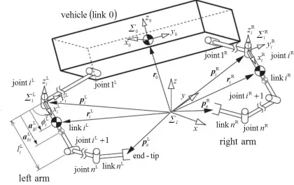
Fig. 2.1 shows the three-dimensional model of a floating underwater vehicle equipped with multi-link dual-arm that is considered in this work.
The model is consists of an inertial coordinate frame ΣI and vehicle coordinate
frameΣ0. Here,ΣIis introduced to describe the motion of the entire UVMS system.
Fig. 2.1: Model of underwater robot equipped with multiple-links dual-arm
with numbers consecutively, starting from the base. Each links of the right arm is numbered from 1 to n. Similarly, each links of the left arm is numbered from 1 to
n. The joint between link i and link (i+ 1) is denoted as joint i. Therefore, the parameters related to both right and left arm can be expressed such as n∗, where ∗ symbol is fixed on the upper right.
In describing the mathematical model of the UVMS, three important assump-tions were made:
• The structure of the robot is a collection of rigid bodies connected by joints. • Although the forces of gravity (weight) and forces of buoyancy of the robot
base and each link are not coincide, the whole system of the robot is in the state of equilibrium.
• The surrounding fluid is in a static condition.
Symbols used in the model are defined as follows:
i∗ : number of joint and link for arm ∗ (∗=R: Right arm,∗=L: Left arm)
n∗ : number of joint for arm∗ (∗=R: Right arm, ∗=L: Left arm)
ΣI : inertial coordinate frame
Σi∗ : link i coordinate frame for arm∗ (∗=R: Right arm, ∗=L: Left arm)
iR∗
j : coordinate transformation matrix of arm∗ from Σj∗ to Σi∗
r0 : position vector of center of gravity for robot base with respect toΣI
p∗e : position vector of end-tip of arm∗ with respect to ΣI
p∗i : position vector of origin of Σi∗ with respect to ΣI
ri∗ : position vector of center of gravity for linki∗ with respect to ΣI
ψ0 : roll-pitch-yaw attitude vector of Σ0 with respect to ΣI
ψe∗ : roll-pitch-yaw attitude vector of end-tip for arm ∗ with respect toΣI
ω0 : angular velocity vector ofΣ0 with respect to ΣI
ωi∗ : angular velocity vector ofΣi∗ with respect to ΣI
ωe∗ : angular velocity vector of end-tip for arm ∗with respect to ΣI
ϕ∗i : relative angle of joint i∗
ϕ : relative joint angle vector (= [(ϕR)T, (ϕL)T]T), (ϕ∗ = [ϕ∗
1, ϕ∗2, · · · , ϕ∗n∗]T)
ki∗ : unit vector indicating a rotational axis of jointi∗ m0 : mass of robot base
m∗i : mass of linki∗
Ma∗
i : added mass matrix of link i
∗ with respect toΣ∗
i
Ii∗ : inertia tensor of linki∗ with respect to Σi∗
Ia∗
i : added inertia tensor of linki
∗ with respect to Σ∗
i
x0 : position and attitude vector ofΣ0 with respect to ΣI (= [r0T, ψ0T]T)
x∗e : position and attitude vector of end tip for arm ∗ with respect to ∗ ΣI (=
[(p∗e)T, (ψ∗ e)T]T)
ν0 : linear and angular velocity vector ofΣ0 with respect toΣI (= [ ˙r0T, ω0T]T)
νe∗ : linear and angular velocity vector of end-tip for arm ∗ with respect to ΣI
(= [( ˙p∗e)T, (ω∗ e)T]T)
li∗ : length of link i∗ a∗g
i : length between joint i
∗ to the center of gravity of link i∗
a∗b
i : length between joint i
∗ to the center of buoyancy of linki∗
il∗
i : position vector of joint (i∗+ 1 ) with respect toΣi
a∗g
i : position vector from joint i
∗ to the center of gravity of link i∗ with respect to
ΣI
a∗b
i : position vector from jointi
∗ to the center of buoyancy of link i∗ with respect
toΣI
Di∗ : width of link i∗ Vi∗ : volume of linki∗
ρ : fluid density
Cd∗
i : drag force coefficient for linki
∗
Ej : j ×j unit matrix
˜˙ : tilde operator stands for a cross product such that ˜ra=r×a
In the field of underwater robotics, when an object moves in a fluid, external hydrodynamic forces comprises of in-line and transverse forces (generated from shed-ding of vortices) are taken into consideration [75]. However, the motions permitted for underwater robots are usually very slow and the magnitude of the transverse forces are relatively small compared to the in-line forces [75, 76]. Thus, only in-line forces containing drag, added mass and fluid-acceleration forces are usually affecting the motions of a slow moving underwater robot. In [75], accurate modeling of added mass and drag forces can be achieved by state-dependent coefficients. However, in general, added mass are identified experimentally using added mass of a simplified shape as the initial value [77]. Thus, the added mass, added moment of inertia and drag coefficient are based on constant values that depends on the shape of the robots that is usually called strip theory [73, 76, 78]. Therefore, in this work, the hydrodynamic forces is obtained by applying the same principle.
2.2.1
Kinematic equation
In order to derive the kinematic and momentum equations, the center of mass for the robot base and arm links, and angular velocities of the arm joints are determined.
First, the position vector p∗i of each jointi∗ (i∗ = 1, 2, · · · , n∗) for both arms, and the position vector ri∗ of the center of mass for each link i∗ can be described as
p∗i =p∗i−1+IRi∗−1i−1l∗i−1, (2.1)
ri∗ =p∗i +IR∗iia∗gi, (2.2) where il∗i = [l∗i, 0, 0]T and Σi∗, ia∗gi = [a∗i, 0, 0]T are the position vectors with respect to Σi∗. Note that p0 = r0.Similarly, the position p∗e of each end-tip for
both arms is
p∗e =p∗n∗+IRn∗∗n
∗
l∗n∗. (2.3)
Next, the linear velocity vector and angular velocity vector for joint i∗ can be de-scribed as
˙
p∗i = ˙p∗i−1+ωi∗−1 ×(IR∗i−1i−1l∗i−1), (2.4)
ω∗i =ω∗i−1+IR∗iik∗iϕ˙∗i. (2.5) Similarly, the linear velocity vector for the center of mass for linki∗ and each end-tip are
˙
˙
p∗e = ˙p∗n∗+ω∗n∗ ×( I
R∗n∗n ∗
l∗n∗). (2.7)
Here,
IR∗ i−1
i−1l∗
i−1 =p∗i −p∗i−1,
IR∗ i
ia∗ gi =r
∗
i −p∗i,
and k∗i is defined as
ki∗ =IR∗iiki∗.
As a result, the linear velocity and angular velocity for jointi∗ based on Equations (2.4) and (2.5) are expressed as
˙
p∗i = ˙p∗i−1+ ˜ω∗i−1(p∗i −p∗i−1) = ˙r0−( ˜p∗i −r˜0)ω0+
i−1
∑
j=1 ˜
k∗j(p∗i −p∗j) ˙ϕ∗j, (2.8)
ω∗i =ω0+
i
∑
j=1
kj∗ϕ˙∗j. (2.9)
In a similar manner, the linear velocity and angular velocity for the center of mass for linki∗ and both end-tips based on Equation (2.7) become
˙
ri = ˙r0−( ˜ri∗−r˜0)ω0+
i
∑
j=1 ˜
k∗j(r∗i −p∗j) ˙ϕ∗j, (2.10) ˙
p∗e = ˙r0−( ˜p∗e−r˜0)ω0+
n∗
∑
j=1 ˜
k∗j(p∗e−p∗j) ˙ϕ∗j, (2.11) and,
ω∗e =ω0+
n∗
∑
j=1
kj∗ϕ˙∗j. (2.12) The kinematic and momentum equations can be determined based on the aforemen-tioned equations.
First, based on Equations (2.11) and (2.12), the relationship between the linear and angular velocity vector for both end-tips νe∗ = [( ˙p∗e)T, (ω∗
e)T] T
, the linear and angular velocity vector of robot base ν0 = [ ˙r0T, ω0T]
T
and angular velocity vector of each joint for both arms ˙ϕ∗ = [ ˙ϕ∗1,ϕ˙2∗, · · · , ϕ˙∗n∗]T can be expressed with
where
A∗ =
[
E3 −( ˜p∗e−r˜0)
0 E3
]
,
B∗ =
[
b∗1 b∗2 · · · b∗n
]
,
b∗i = [{k˜∗i(p∗e−p∗i)}T, (k∗i)T]T.
Moreover, based on Equation (2.13), linear and angular velocity vector for both end-tips νe = [(νeR)T, (νeL)T]
T
, linear and angular velocity vector for robot base
ν0 = [ ˙r0T, ω0T]
T
and angular velocity of each joint on both arms ˙ϕ= [( ˙ϕR)T, ( ˙ϕL)T]T
can be summarized into a single kinematic equation as
νe =Aν0 +Bϕ˙, (2.14) where
A=
[
AR
AL
]
,
B=
[
BR 0
0 BL
]
2.2.2
Momentum equation
In this section, the linear momentum of the robot overall system η and angular momentum around the center of mass of the robot baseµcontaining hydrodynamic added mass iM∗
ai and added inertia moment
iI∗
ai are determined. Here, the linear momentum of the robot overall systemηis considered to consist of linear momentum of the robot baseη0, linear momentum of the right arm ηR and linear momentum of the left armηL. Similarly, the angular momentum around the center of mass of the robot base µ is also considered to consist of angular momentum of the robot base
µ0, angular momentum of right arm µR and angular momentum of left armµL. Therefore, linear momentumη and angular momentumµ are expressed as
η=η0+ηR+ηL =MT0r˙0+η
R +ηL, (2.15)
µ=µ0+µR+µL−r0×η =IT0 ω0+r0×MT0r˙0+µ
R+µL−r
0×η, (2.16) where
η∗ =
n∗
∑
i=1
MT∗ir˙i∗,
µ∗ =
n∗
∑
i=1
IT∗iωi∗+ ˜ri∗MT∗ir˙∗i,
MT0 =m0E3+
IR
00Ma0 0R
I,
IT0 =
IR
0(0I0 +0Ia0) 0R
I,
MT∗
i =m
∗
iE3+IR∗i iM∗
ai
iR∗ I,
IT∗i =IR∗i(iIi∗+iIa∗i)iR∗I.
momentum µthat can be described as
η=MT0r˙0+
nR
∑
i=1
MTRir˙Ri +
nL
∑
i=1
MTLir˙Li =MT0r˙0+M
R
Ti
{
˙
r0−( ˜riR−r˜0)ω0+
i
∑
j=1 ˜
kRj(riR−pRj) ˙ϕRj
}
+MTLi
{
˙
r0−( ˜riL−r˜0)ω0+
i
∑
j=1 ˜
kjL(rLi −pLj) ˙ϕLj
}
=
MT0 +
nR
∑
i=1
MTR
i+
nL
∑
i=1
MTL
i
r˙0 − nR ∑ i=1
MTR
i( ˜r R
i −r˜0)−
nL
∑
i=1
MTL
i( ˜r L
i −r˜0)
ω0
+ nR ∑ i=1 nR ∑
j=i
MT∗
i ˜
kRi (rjR−pRi ) ˙ϕRi +
nL
∑
i=1
nL
∑
j=i
MT∗
i ˜
kLi(rjL−pLi) ˙ϕLi, (2.17)
µ=IT0ω0+r0×MT0r˙0+
nR ∑
i=1 (
ITRiωiR+ ˜riRMTRir˙iR)+
nL ∑
i=1 (
ITLiωiL+ ˜riLMTLir˙Li)
−r0×
MT0r˙0+
nR ∑
i=1
MTRir˙Ri +
nL ∑
i=1
MTLir˙iL
=IT0ω0+
nR ∑
i=1 {
ITRiωRi + ( ˜riR−r˜0)MTRir˙ R i } + nL ∑ i=1 {
ITLiωiL+ ( ˜rLi −r˜0)MTLir˙ L i } = nR ∑ i=1
( ˜riR−r˜0)MTRi+
nL ∑
i=1
( ˜riL−r˜0)MTLi r˙0
+ IT0+
nR ∑
i=1 {
ITRi−( ˜rRi −r˜0)MTRi( ˜r R
i −r˜0) } + nL ∑ i=1 {
ITLi−( ˜riL−r˜0)MTLi( ˜r L
i −r˜0) }
ω0
+ nR ∑ i=1 nR ∑
j=i
{
ITRj−( ˜rjR−r˜0)MTRj( ˜r R
j −p˜Ri )
}
kRi ϕ˙Ri
+ nL ∑ i=1 nL ∑
j=i
{
ITLj−( ˜rjL−r˜0)MTLj( ˜r L
j −p˜Li)
}
Thus, based on Equations (2.17) and (2.18), the following momentum equation can be obtained: s= [ η µ ]
=Cν0+Dϕ,˙ (2.19)
where
C = [
c11 c12
c21 c22 ]
,
D=
[
dR
11 dR12 · · · dR1nR dL11 dL12 · · · dL1nL
dR21 dR22 · · · dR2nR dL21 dL22 · · · dL2nL ]
,
c11=MT0+
nR ∑
i=1
MTRi+
nL ∑
i=1
MTLi,
c12=−
nR ∑
i=1
MTRi( ˜rRi −r˜0)−
nL ∑
i=1
MTLi( ˜riL−r˜0),
c21=−r˜0MT0 +
nR
∑
i=1 ˜
riRMTRi+
nL
∑
i=1 ˜
rLiMTLi,
c22=IT0 +
nR ∑
i=1
ITRi−
nR ∑
i=1
( ˜ri∗−r˜0)MTRi( ˜r R
i −r˜0) +
nL ∑
i=1
ITLi−
nL ∑
i=1
( ˜ri∗−r˜0)MTLi( ˜r L
i −r˜0),
d∗1i =
n∗
∑
j=i
MT∗ik˜∗i(r∗j −p∗i),
d∗2i=
n∗
∑
j=i
IT∗jk∗i + ( ˜r∗i −r˜0)MT∗jk˜
∗
i(rj∗−p∗i).
2.2.3
Drag forces and buoyant forces
The hydrodynamic drag forces, drag moment and buoyant forces acting on an object that moves in 3-dimensional space are described in this section. Drag force onxi axis direction
elementifx∗,and drag momentinf∗xgenerated byifx∗that acted on linki∗can be expressed as follows [77]:
if∗ x =
ρ
2C
∗
Di ∫ lz1
−lz2 ∫ ly1
−ly2
References
[1] WM. Blake Tyrrell: “Star Trek as myth and television as mythmaker”, The Journal of Popular Culture, 10(4):711-719, 1977.
[2] A. Pigafetta and R. A. Skelton: “Magellan’s voyage: A narrative account of the first
circumnavigation”, Courier Dover Publications, 1994.
[3] J. Piccard: “Seven miles down: The story of the Bathyscaph Trieste”, Putnam Pub-lisher, First Edition, 1961.
[4] E. H. Oelkers, J. G. Hering and Z. Chen: “Water: Is there a global crisis?”, Elements, 7(3):17-162, 2011.
[5] X. Chen: “Why do people misunderstand climate change? Heuristics, mental models
and ontological assumptions”, Climatic Change:108(1-2), pp. 31-46, 2011.
[6] P. H. Gleick: “Water in crisis: A guide to the world’s fresh water resources”, Ecolog-ical Applications 8:571-579, 1993.
[7] R. Moore: “A time to die: The untold story of the Kursk tragedy”, New York: Crown Publishers, Random House, 2003.
[8] G. Williamset al.: “Thick and deformed Antarctic sea ice mapped with autonomous
underwater vehicles”, Nature Geoscience, 8:61-67, 2015.
[9] C. J. Cleveland, M. Hogan and P. Saundry: “Deepwater Horizon oil spill”, In Ency-clopedia of Earth, Environmental Information Coalition, National Council for Science
and the Environment, 2011.
[10] R. A. Church, D. J. Warren, A. W. Hill and J. S. Smith: “The discovery of U-166: Rewriting history with new technology”, Proceedings of Offshore Technology
Conference, OCT 14136, 2000.
[11] J. C. Kincey et al.: “Assessing the Deepwater Horizon oil spill with the sentry
[12] Internet article: “Scorpio 45: The UK’s deep-sea rescuer”,
http://news.bbc.co.uk/2/hi/uk news/4128728.stm (accessed on 26th December 2014).
[13] Internet sourced image: https://www.flickr.com/photos/pallo/208447927 from
Pal-Loberg (accessed on 8th June 2015).
[14] Internet article: “Russia to buy Scorpio underwater robots after rescue of trapped sub”, http://www.spacewar.com/2005/050809073845.lqzme3ki.html (accessed on
26th December 2014).
[15] Internet article: “Seaeye develops new markets while energy sector continues to
boom”, http://www.seaeye.com/whatsnew 2006.html (accessed on 26th December 2014).
[16] Internet article: “University of New Orleans to develop underwater spy
robot”, http://navaltoday.com/2011/08/09/university-of-new-orleans-to-develop-underwater-spy-robot-usa/ (accessed on 26th December 2013).
[17] Internet article: “Underwater robot sheds new light on Antarctic sea ice”,
http://www.whoi.edu/newsrelease/SeabedAntarctic (accessed on 7th June 2015).
[18] A. Bleicher: “The Gulf spill’s lessons for robotics”, IEEE Spectrum, vol. 47, no. 3, pp. 9-11, 2010.
[19] Internet article: “Rewriting history with new oilfield technology”, http://www.geotimes.org/aug02/feature oil.html (accessed on 8th June 2015).
[20] G. Troni, J. C. Kinsey, D. R. Yoerger and L. L. Whitcomb: “Field performance
evaluation of new methods for in-situ calibration of attitude and doppler sensors for underwater vehicle navigation”, Proceedings of 2012 International Conference on Robotics and Automation (ICRA), pp. 5334-5339, 2012.
[21] Internet article: “Underwater robot to stake Canada’s Arctic claim”, http://www.theepochtimes.com/n2/canada/efforts-on-track-to-determine-limits-of-continental-shelf-for-land-claim-to-un-commission-by-2013-32982.html (accessed
on 8th June 2015).
[22] Internet article: “Underwater robots at work in Japan”, http://cosmiclog.msnbc.msn.com/
news/2011/04/21/6508009-underwater-robots-at-work-in-japan (accessed on 8th June 2015).
[23] R. R. Murphyet al.: “Use of remotely operated marine vehicles at Minamisanriku and
[24] F. Søreide: “Ships from the depths: Deepwater archaeology”, Texas A & M University
Press, pp. 29-40, 2011.
[25] M. A. Moline: “Remote environmental monitoring units: An autonomous vehicle for characterizing coastal environments”, Journal of Atmospheric and Oceanic
Technol-ogy, 22(11):1797-1808, 2005.
[26] D. R. Blidberg: “The development of autonomous underwater vehicles (AUVs); A brief summary”, Proceedings of IEEE International Conference on Robotics and Au-tomation (ICRA), 2001.
[27] V. Rigaudet al.: “UNION: underwater intelligent operation and navigation”, IEEE
Robotics & Automation Magazine, vol. 5, no. 1, pp. 25-35, 1998.
[28] M. Kyo et al.: “The sea trial of ”KAIKO”, the full ocean depth research ROV”, Proceedings of MTS/IEEE OCEANS 1995, vol. 3, pp. 1991-1996, 1995.
[29] B. H. Junet al.: “Workspace control system of underwater tele-operated manipulators
on ROVs”, Proceedings of IEEE/MTS OCEANS 2009-EUROPE, pp. 1-6, 2009.
[30] S. Sagara et al.: “Experiments on a floating underwater robot with a two-link ma-nipulator”, Artificial Life and Robotics 5:215-219, 2001.
[31] A. D. Bowenet al.: “The Nereus hybrid underwater robotic vehicle for global ocean science operations to 11,000m depth”, Proceedings of IEEE/MTS OCEANS 2008,
pp. 1-10, 2008.
[32] R. Yanget al.: “Modeling of a complex-shaped underwater vehicle”, Proceedings of 2014 IEEE International Conference on Autonomous Robot Systems and
Competi-tions (ICARSC), pp. 36-41, 2014.
[33] H. Wang, S. Rock and M. J. Lee: “OTTER: The design and development of an intelligent underwater robot”, Autonomous Robots, vol. 3, issue 2-3, pp. 297-320,
1996.
[34] H. T. Choi, S. K. Choi and J. Yuh: “Development of an underwater robot, ODIN-iii”, Proceedings of 2003 IEEE/RSJ International Conference on Intelligent Robots and Systems, vol. 1, pp. 836-841, 2003.
[35] J. Yuh et al.: “Design of a semi-autonomous underwater vehicle for intervention
missions (SAUVIM)”, Proceedings of International Symposium on Underwater Tech-nology. pp. 63-68, 1998.
[36] G. De Novi et al.: “A new approach for a reconfigurable autonomous underwater
[37] J. Evanset al.: “Autonomous docking for Intervention-AUVs using sonar and
video-based real-time 3D pose estimation”, Proceedings of IEEE/MTS OCEANS 2003, vol. 4, pp. 2201-2210, 2003.
[38] D. M. Laneet al.: “AMADEUS: Advanced manipulation for deep underwater
sam-pling”, IEEE Robotics and Automation Magazine, vol. 4, no. 4, pp. 34-45, 997.
[39] T. Fujii and T. Ura: “Development of an autonomous underwater robot “Twin-Burger” for testing intelligent behaviors in realistic environments”, Autonomous Robots, vol. 3, pp. 285-296, 1996.
[40] R. D. Christ and R. L. Wemli Sr.: “The ROV manual: A user guide for remotely
operated vehicles”, Butterworth-Henemann Publisher, Second edition, 2013.
[41] G. Antonelli: “Underwater robots: Motion and force control of vehicle-manipulator systems”, 2nd Edition, Springer Tracts in Advanced Robotics, vol. 2, pp. 1-13, 2006.
[42] J. Yuh: “Design and Control of Autonomous Underwater Robots: A Survey”, Au-tonomous Robots, vol. 8, pp. 7-24, 2000.
[43] M.W. Dunnigan and G.T. Russell: “Evaluation and reduction of the dynamic
cou-pling between a manipulator and an underwater vehicle”, IEEE Journal of Oceanic Engineering, vol. 23, no. 3, pp. 260-273, 1998.
[44] B. Xu, S. Abe, N. Sakagami and S. R. Pandian: “Robust nonlinear controller for
underwater vehicle-manipulator systems”, Proceedings of 2005 IEEE/ASME Inter-national Conference on Advanced Intelligent Mechatronics, pp. 711-716, 2005.
[45] S. Soylu, B. J. Buckham and R. P. Podhorodeski: “Development of a coordinated controller for underwater vehicle-manipulator systems”, Proceedings of IEEE/MTS
OCEANS 2008, pp. 1-9, 2008.
[46] H. Mahesh, J. Yuh and R. Lakshmi: “A coordinated control of an underwater vehicle and robot manipulator”, Journal of Robotic Systems, vol. 8, pp. 339-370, 1991.
[47] N. Sarkar, J. Yuh, T. K. Podder: “Adaptive control of underwater
vehicle-manipulator systems subject to joint limits”, Proceedings of 1999 IEEE/RSJ Interna-tional Conference on Intelligent Robots and Systems (IROS’99), vol. 1, pp. 142-147, 1999.
[48] G. Antonelli and S. Chiaverini: “Adaptive tracking control of underwater
vehicle-manipulator systems based on the virtual decomposition approach”, IEEE Transac-tions on Robotics and Automation, vol. 20, no. 3, pp. 594-602, 2004.
[49] S. Mohan and J. Kim: “Indirect adaptive control of an autonomous underwater
[50] G. Antonelli and S. Chiaverini: “Fuzzy redundancy resolution and motion
coordi-nation for underwater vehicle-manipulator Systems”, IEEE Transactions on Fuzzy Systems, vol. 11, no. 1, pp. 109-120, 2003.
[51] S. Soylu, B. J. Buckham and R. P. Podhorodeski: “Redundancy resolution for un-derwater mobile manipulators”, Ocean Engineering, vol. 37, pp. 325-343, 2010.
[52] S. McMillan, D. E. Orin and R. B. McGhee: “Efficient dynamic simulation of an un-manned underwater vehicle with a manipulator”, 1994 IEEE International Conference on Robotics and Automation (ICRA), vol. 2, pp. 1133-1140, 1994.
[53] T. J. Tarn, G. A. Shoults and S. P. Yang: “A dynamic model of an underwater vehicle with a robotic manipulator using Kane’s method”, Autonomous Robots, vol. 3, pp.
269-283, 1996.
[54] N. Kato and D. M. Lane: “Co-ordinated control of multiple manipulators in under-water robots”, Proceedings of 1996 IEEE International Conference on Robotics and
Automation, vol. 3, pp. 2505-2510, 1996.
[55] R. Mukherjee and Y. Nakamura: “Formulation and efficient computation of inverse
dynamics of space robots”, IEEE Transactions on Robotics and Automation, vol. 8, no. 3, pp. 400-406, 1992.
[56] N. Sarkar and T. K. Podder: “Coordinated motion planning and control of au-tonomous underwater vehicle-manipulator systems subject to drag optimization”, IEEE Journal of Oceanic Engineering, vol. 26, no. 2, pp. 228-239, 2001.
[57] Y. Cui and J. Yuh: “A unified adaptive force control of underwater vehicle-manipulator systems (UVMS)”, Proceedings of IEEE/RSJ International Conference
on Intelligent Robots and Systems, pp. 553-558, 2003.
[58] J. Han, J. Park and W. K. Chung: “Robust coordinated motion control of an
un-derwater vehicle-manipulator system with minimizing restoring moments”, Ocean Engineering, vol. 38, pp. 1197-1206, 2011.
[59] O. Korkmaz, S.K. Ider, and M.K. Ozgoren: “Control of an underactuated
underwa-ter vehicle manipulator system in the presence of parametric uncertainty and distur-bance”, American Control Conference (ACC), pp. 578-584, 2013.
[60] T. W. McLain, S. M. Rock and M. J. Lee: “Experiments in the coordinated control of an underwater arm/vehicle system”, Autonomous Robots, vol. 3, pp. 214-232, 1996.
[62] S. Sagara, T. Yatoh and T. Shimozawa: “Digital RAC with a disturbance observer
for underwater vehicle-manipulator systems”, Artificial Life and Robotics 15:270-274, 2010.
[63] G. Antonelli, T. I. Fossen and D. R. Yoerger: “Underwater robotics”, Springer
Hand-book of Robotics, pp. 987-1008, 2008.
[64] J. O. Gray and D. G. Caldwell: “Advanced robotics and intelligent machines”, Insti-tution of Electrical Engineers, 1st Edn, 1996.
[65] A. A. Goldenberget al.: “A remote manipulator for forestry operation”, IEEE Trans-action on Robotics and Automation, vol 11, no. 2, pp. 185-197, 1995.
[66] S.-U. Lee et al.: “Development of a Tele-operated Underwater Robotic System for
maintaining a light-water type power reactor”, Proceedings of International Joint Conference SICE-ICASE, pp. 3017-3021, 2006.
[67] F. Takemura and R. T. Shiroku: “Development of the actuator concentration type
removable underwater manipulator”, Proceedings of 11th International Conference on Control Automation Robotics and Vision (ICARCV), pp. 2124-2128, 2010.
[68] S. Soylu et al.: “Comprehensive underwater vehicle-manipulator system teleopera-tion”, Proceedings of MTS/IEEE OCEANS 2010, pp. 1-8, 2010.
[69] J. J. Yao et al.: “Development of a 7-function hydraulic underwater manipulator
system”, Proceedings of 2009 IEEE International Conference on Mechatronics and Automation, pp. 1202-1206, 2009.
[70] M. Shibata, T. Saito, N. Sakagami and S. Kawamura: “Simultaneous operation of
dual arm and body of mobile robots”, Proceedings of 2010 IEEE International Con-ference on Robotics and Biomimetics (ROBIO), pp 2010, pp. 149-154, 2010.
[71] K. Kawano, T. Shimozawa, and S. Sagara: “A master-slave control system for a
semi-autonomous underwater vehicle-manipulator system”, Artificial Life and Robotics, vol. 16, pp. 465-468, 2012.
[72] M. Prats, J. J. Fernandez and P. J. Sanz: “An approach for semi-autonomous recovery of unknown objects in underwater environments”, Proceedings of OPTIM, pp.
1452-1457, 2012.
[73] T. I. Fossen: “Guidance and control of ocean vehicles”, John Wiley & Sons, pp. 431-452, 1995.
[74] S. Sagara: “Resolved acceleration control of underwater vehicle-manipulator systems:
[75] T. W. McLain and S. M. Rock: “Development and experimental validation of an
underwater manipulator hydrodynamic model”, International Journal of Robotics Research,vol. 17,no. 7,pp. 748-759,1998.
[76] S. McMillan, D. E. Orin and R. B. McGhee: “Efficient dynamic simulation of an
underwater vehicle with a robotic manipulator”, IEEE Transactions on Systems, Man, and Cybernetics, 25(8):1194-1206, 1995.
[77] M. Tamura, “Experimental study on resolved acceleration control for underwater vehicle-manipulator systems”,Ph.D. Thesis, Kyushu Institute of Technology, 2006.
(in Japanese)
[78] B. L’evesque and M. J. Richard: “Dynamic analysis of a manipulator in a fluid environment”, International Journal of Robotics Research, vol. 13, no. 3, pp.
221-231, 1994.
[79] J. Fukuda, “Experimental study on measuring propulsion of thruster for underwater vehicle using infrared sensor”,Bachelor Degree Thesis, Kyushu Institute of Technol-ogy, 2008. (in Japanese)
[80] G. Antonelli: “Underwater robots”, Springer, pp. 1194-1206, 2003.
[81] R. B. Ambar, S. Sagara and F. Takemura: “Development of manipulator joint for underwater vehicle-manipulator system using neodymium magnetic coupling - appli-cation on a 2-link manipulator”, No.13-2 Proceeding of the 2013 JSME Conference
on Robotics and Mechatronics, 2A2-M08, 2013.
[82] R. B. Ambar, S. Sagara and K. Imaike: “Experiment on a dual-arm underwater robot using resolved acceleration control method”, Artificial Life and Robotics, 20(1):
34-41, 2014.
[83] R. Ravaud and G. Lemarquand: “Magnetic couplings with cylindrical and plane air gaps: Influence of the magnet polarization direction”, Progress In Electromagnetics Research B, vol. 16, pp. 333-349, 2009.
[84] K. Yoshida, S. Abiko and J.M. Ota: “Development of an articulated gripper for an
underwater ROV”, Transaction of the Japan Society of Mechanical Engineers, ser.C, vol.68, no.675, pp. 237-244, 2002.
[85] M. Ishitsuka and K. Ishii: “Development and control of an underwater manipulator
for AUV”, Proceedings of Symposium on Underwater Technology and Workshop on Scientific Use of Submarine Cables and Related Technologies, pp. 337-342, 2007.
[86] T. W. McLain: “Modeling of underwater manipulator hydrodynamics with
[87] K. N. Leabourne and S. M. Rock: “Model development of an underwater
manipula-tor for coordinated arm-vehicle control”, Proceedings of IEEE/MTS OCEANS 1998, vol.2, pp. 941-946, 1998.
[88] Q. Zhang, A. Zhang and K. Yan: “Improved design and control experiments of an underwater electric manipulator”, Proceedings of 2006 SICE-ICASE International
Joint Conference, pp. 3089-3093, 2006.