COMPARISON OF JAMMING EXCISION METHODS FOR
DIRECT SEQUENCE/SPREAD SPECTRUM (DS/SS)
MODULATED SIGNAL
1 GIAN CARLO CARDARILLI, LUCA DI NUNZIO, ROCCO FAZZOLARI, AMIRHOSSEIN
FEREIDOUNTABAR, FILIPPO GIULIANI, MARCO RE
2
LORENZO SIMONE
1
University of Rome Tor Vergata, Via del Politecnico 1, 00133, Rome, Italy;
2
Thales Alenia Space Rome - Transponder Group, Via Saccomuro 19-21, 00131, Rome, Italy;
E-mail: 1 [email protected], [email protected]
ABSTRACT
Direct Sequence/Spread-Spectrum (DSSS) signals are characterized by a wide bandwidth and a low-power spectral density. These characteristics make them very robust with respect to the jamming.
The Jamming represents one of the main concerns for secure communication and communication in a crowded spectrum. When the jamming to signal power ratio is greater than the Process Gain, even the use of DSSS signals requires the introduction of mitigation techniques.
Common anti-jamming systems are based on adaptive filters. However, this solution presents several disadvantages, as the inefficiency to mitigate multi-tone jamming and nonstationary jamming.
For these reasons, great interest is toward the development of anti-jamming systems based on different techniques as the Wavelet Transform and the Filters bank.
This paper has two objectives. The first one regards the evaluation of the parameter choice on the jamming excision performance. The second objective is to compare the performance obtainable by the two above techniques.
Experiments for parameter evaluation and performance comparison are carried out using MATLAB simulations. These simulations were performed using the most common jamming types.
Keywords: Jamming Excision; Wavelet Packet Decomposition; DSSS; DWT; Polyphase Filters Bank
1. INTRODUCTION
Spread Spectrum techniques spread band-limited signals in the frequency domain resulting in a signal with a wider spectrum. Such techniques are used to prevent signal detection and to increase the resistance to noise and jamming. However, if the jamming to signals power ratio is
greater than the Process Gain (GP), the jamming
mitigation cannot be accomplished. In these cases, additional jamming excision techniques are required [1][2]. For example, in space applications satellites are equipped with additional anti-jamming systems, usually based on adaptive filters. However, the use of adaptive filters presents several disadvantages, as the difficulty to mitigate multi-tone jamming and the inefficiency to operate with nonstationary jamming [3]. Consequently, a large number of alternative techniques have been proposed in the literature for
the rejection of the jamming for DSSS based systems [4] [5] [6]. In this frame, a number of papers are focused on the anti-jamming systems based on time frequency analysis, as in the case of the Wavelet Transform and the Filter Banks [6] [7] [8] [9] [10] [11] [12] [13] [14].
These works show the usefulness of these techniques for the jamming excision in spread-spectrum signals.
The analysis of the literature indicates the lack of some important information for an efficient usage of these methods:
1. A complete comparison of the two
techniques (Wavelet Transform and Filter Banks) in this specific application.
2. An analysis concerning the impact of the
selection of Wavelet Transform and Filter
Banks parameters on the system
The purpose of this work is to fill these lacks providing 1) a detailed comparison between the two methods in terms of jamming mitigation;2) an analysis of the impact of the parameters for the two methods on the system performance. This analysis has been performed in order to support the design of the excision system.
For each method, the following parameters have been considered:
• Wavelet: selection of mother wavelet, number of decomposition levels, filter latency and number of mother wavelet samples.
• Polyphase Filter Banks: filter order and number of channels.
2. TIME/FREQUENCY JAMMING EXCISION TECHNIQUES
The jamming is mostly used in electronic warfare, and, together with the deception and the direct energy, is one of the main strategies of electronic attacks. A jammer disturbs the radio communication link using active signals. It reduces the information availability slowing down the communication process.
The most common types of jamming are Tone Jamming, Pulse Jamming, Swept Jamming and Hop Jamming.
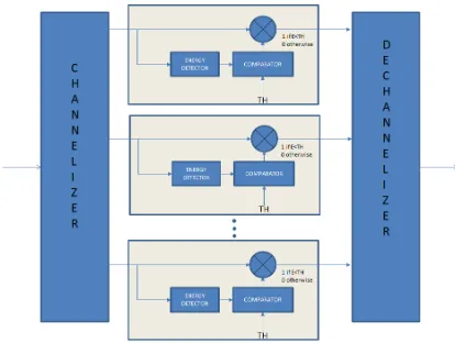
An approach used to separate the signal from the jamming in spread spectrum systems is the excision of the portion of spectrum where the interference is located (see Fig. 1). Fig. 2 shows the basic structure of an excision system. In this structure, the signal is decomposed in sub-bands through a channelizer. Energy detectors are used for revealing the presence of the jamming in the bands. The jamming is present when in a sub-band the energy is above a given threshold. After the detection, the sub-bands with jamming are erased. Finally, the output signal (jamming free) is obtained recombining the sub-bands through the dechannelizer.
Channelization and de-channelization can be realized using different techniques. Common techniques are based on the Discrete Wavelet
Transform (DWT) [15] and Perfect
Reconstruction (PR) Filter Banks [16].
2.1 Discrete Wavelet Transform
The DWT is a linear time-frequency transformation. Unlike the Fourier transform, that correlates a signal with complex exponential
[image:2.612.322.509.189.319.2]waveforms, the Wavelet Transform correlates the signal with scaled and translated versions of a finite length waveform called mother wavelet. DWT can be obtained using a Wavelet Packet Tree [17]
Figure 1: DSSS Spectrum: (A) In Presence Of Jammer, (B) After Excision
Figure 2: Structure Of The Excision System For The Jamming Rejection
Assuming an N-level tree, the result of the
Wavelet Packet Tree is a structure of 2N channels.
This operation is also called Wavelet Packet
[image:2.612.318.525.377.533.2]Figure 3: WPD Structure
The inverse operation is called Wavelet Packet
Reconstruction (WPR). The WPD and the WPR
can be used to excise a jammer from a DSSS signal [6].The WPD acts as a channelizer. It splits
the signal into 2N sub-bands, where N is the
number of decomposition levels. For each sub-band, the presence of the jamming can be detected using the energy detectors. The sub-bands where the jammer is located are erased and, finally, the signal is reconstructed by the WPR.
2.2 Polyphase filter bank
Filter banks are very useful in many applications, as radar, voice analysis, satellite telecommunications etc.. Moreover, the use of the "polyphase" decomposition allows to reduce the hardware resources required for the filter bank realization [18].
The strategy for the jamming rejection using the polyphase filter banks is similar to that baesd on the DWT. The signal is decomposed in N sub-bands, using an analysis filter bank. Then, each sub-band is processed erasing the jamming affected channels and, finally, the signal is reconstructed by a synthesis filter bank.
The use of polyphase filter banks for the jamming excision implies that the analysis and
synthesis filters must own the perfect
reconstruction property. This feature needs the satisfaction of two constraints [16];
• No amplitude and phase distortions.
• Not critically sampled filter-banks, in order to
avoid aliasing.
If one of these constraints is not satisfied, the system is said Nearly Perfect Reconstruction
(NPR). In our case, both the prototype filter used for the analysis and that used for the synthesis respect the above constraints. In order to realize a non-critically sampled filter bank, the coefficient set of the sub-filters must be obtained by the prototype filter impulse response according to Eq 1 [16]:
1
0,1...K
ρ
ρ),
h(Mm
(m)
ρ
p
=
−
=
−
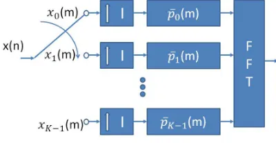
(1)where h(m) is the impulse response of the prototype filter, K is the number of sub-bands and M is the decimation ratio. The block diagram of a non-critically sampled polyphase filter bank is shown in Fig. 4.
Figure 4: Not Critically Sampled Analysis Polyphase Filter Bank
The interpolation blocks implement the non-critical sampling. They increase the sampling rate of a factor I with K=I*M
3. ANALYSIS SCENARIO
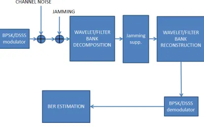
The two main objectives of the paper are the comparison of the WPD and the PR Filter Banks, and the analysis of the impact of the parameters on the mitigation performance. These obectives were fulfilled thorough intensive simulations. Different systems with different parameter values were simulated considering a DSSS signal (with random data) with added jamming. The overall performance was measured by the Bit Error Rate (BER) of the output signal after the jamming removing. Simulations have been carried out using MATLAB, according to the following steps.
• Generation of BPSK DSSS modulated
signal,
• Generation and addition of the jamming to
the DSSS signal,
• Sub-band decomposition using WPD or
[image:3.612.323.523.293.397.2]• Sub-band energy estimation for jamming detection (see the central block in Fig. 2),
• Erasing of the sub-bands affected by the
jamming,
• Reconstruction of the signal using the
WPR or the synthesis polyphase filter bank,
• Demodulation of the BPSK DSSS signal,
BER estimation
[image:4.612.91.292.288.413.2]
The block diagram of the simulation model is show in Fig. 5
Figure 5: Simulation Block Diagram
The simulation scenario emulates a satellite communication link. The simulation parameters were chosen taking into account the definition of the Process Gain in Eq. 2
b c
c b p
R
R
T
T
G
=
=
(2)where Tb is the period of the bit, Tc is the period
of the chip and Rc and Rb are the rates of the chip
and the bit, respectively. A carrier frequency of 10 MHz and a sampling frequency of 40 MHz were used. Choosing a chip rate of 2 Mchip/s and a bit
rate of 16 Kb/s we obtain a process gain Gp = 21
dB. With a Jammer-to-Signal Ratio JSR = 30dB, the bit-error probability is P2 = 0.31 [19]. This
error probability doesn't allow to establish a reliable communication (some communication
links require an error probability below 10-6).
Consequently, the transmission in this channel requires the introduction of a system for the jamming removal.
For single-tone jamming, three different tones were considered. Their carrier frequencies are F1
= 9.95 MHz, F2 = 9.90 MHz and F3= 10.15 MHz. The period of the pulsed jamming is 1ms with a duty cycles of 25 % (250 µs).
The swept jamming was simulated considering a linear sweep from 9.75 MHz to 10.25MHz. The hop jamming randomly changes carrier frequency in a range from 9 MHz to 11 MHz . Performances have been evaluated in terms of BER vs EB/N0. In order to speed-up the simulation, the Bit Error Rate (BER) was
estimated using the semi-analytic method
proposed in [20].
4. JAMMING EXCISION USING
WAVELET PACKET DECOMPOSITION
WPD is characterized by several parameters, as the wavelet mother family and the number of decomposition levels. In the following sections, we will investigate about the impact of these parameters on the jamming excision performance. For our experiments the following parameters are considered:
• Mother wavelet,
• Number of levels of decomposition,
• Number of coefficients,
• Length of energy integration interval.
4.1 Mother Wavelet
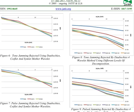
The first analyzed parameter is the mother wavelet. Several simulations were performed in order to determinate the most suitable mother wavelet for jamming excision. The choice has been performed among the three most used wavelets present in literature: Daubechies, Coiflet and Symlet. Fig. 6 and Fig. 7 represent the BER versus Eb/N0 for tone jamming and a pulsed jamming, respectively, using: Daubechies (blue lines), Coiflet (red lines) and Symlet (green lines). Similar results were found for the swept and the hop jamming.
Figure 6: Tone Jamming Rejected Using Daubechies, Coiflet And Symlet Mother Wavelet.
Figure 7: Pulse Jamming Rejected Using Daubechies, Coiflet And Symlet Mother Wavelets.
4.2 Level of decomposition
After the determination of the wavelet family, the next parameter analyzed in the study is the decomposition level (N). Using Daubechies db4 (where 4 is the filter order) as mother wavelet, different values of N have been considered. The input signal was corrupted with a tone jamming (Fig. 8) and a pulsed jamming (Fig. 9).
Simulations results showed a progressive improvement in the BER when the number of decomposition levels N increases. After a certain value of N, curves show a saturation of the BER (see Fig. 8 and Fig. 9) and, in some cases, there is a performance degradation.
Figure 8:Tone Jamming Rejected By Daubechies 4
Wavelet Method Using Different Levels Of Decomposition.
Figure 9:Pulsed Jamming Rejected By Daubechies 4
Wavelet Method Using Different Levels Of Decomposition.
This behavior can be justified considering that the increasing of N corresponds to decrease the bandwidth of the single sub-band. Consequently, the excision of a sub-band has a reduced impact on the spectrum of original signal. Of course, the sub-band narrowing is limited by the selectivity of the filter used in WPD. This limited selectivity is the reason of the BER saturation.
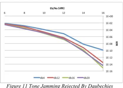
Using a wavelet with higher order filter, as a Daubechies 20 (db20), the BER increases (see Fig. 10), and it is possible to achieve better performance at expense of a greater computation complexity. For swept jamming the relationships
between number of coefficients and
decomposition levels, for N=8, 9, 10 are shown in Figs. 16, 17 and 13, respectively. This aspect will
4.6.
Figure 10Tone Jamming Rejected By Daubechies 20
Wavelet Method Using A High Order Filters
4.3 Number of Coefficients
The mother wavelet can be represented with a different number of samples. Increasing the number of samples, the filter becomes more selective but the filter delay will increase. Moreover, since the computational complexity grows with the number of coefficients, it is important to find the correct trade-off between the
complexity and the jamming mitigation
[image:6.612.324.536.298.444.2]performance.
Figure 11Tone Jamming Rejected By Daubechies
Wavelet Method Using Different Number Of Coefficients.
Figs. 11, 12 and 13 show the effects of the number of coefficients on the performances, considering the 10 levels of decomposition (according to the results presented in previous sections, this values gives an acceptable BER) and changing the number of coefficients from 4 to 20. Experiments are performed using the following jamming types: tone jamming (Fig. 11), pulsed
jamming (Fig. 12) and a swept jamming (Fig. 13).
In the case of tone jamming the results improve with the increasing of number of coefficients reaching a good performance for db16. For analyzing the other cases (pulsed and swept jamming) it is important to observe that the increase of the number of coefficients improves the selectivity of the filter used by WPD and consequently the frequency resolution. However, the time resolution decreases with the increasing of the number of coefficients (the transient response is longer). So, a good solution is obtained trading-off these two elements.
Experiments show that for pulsed jamming the increasing of frequency resolution implies a worsening of the time resolution.
Figure 12 Pulsed Jamming Rejected By Daubechies Wavelet Method Using Different Number Of
Coefficients.
For a swept jamming, the worsening of the time resolution is predominant. This effect is shown in Fig. 13. This type of jamming will be further discussed in section 4.6.
4.4 Length of energy integration interval
As mentioned above (see Sect. 4), the excision algorithm uses an energy detector at the output of each sub-band to estimate the presence of the Jamming in sub-bands.
[image:6.612.90.299.435.585.2]Figure 13 Swept Jamming Rejected By Daubechies Wavelet Method Using Different Number Of Coefficients And 10 Levels Of Decomposition.
In order to promptly capture the temporary presence of jamming in a specific sub-band, a short integration time should be required.
However, a reduced integration interval makes the detector more sensitive to the noise.
Simulations showed that the shortest time integration interval for obtaining good results, is equal to the delay time of the WPD filter. Stimulating the system with a 10MHz tone, the output of 33rd sub-band has the trend shown in Fig. 14.
[image:7.612.99.293.497.629.2]Tab. 1 shows the delay times resulting from the simulations, for different WPD parameters. To further reduce the wrong detections, the energy integration times used in the final system are twice those of Tab. 1.
Figure 14 Output Of The 33rd Sub-Band Of A WPD With A 10mhz Tone As Input And With Db4 As Wavelet
Function.
Table 1. Delay Time Measured At The Output Of A WPD With A 10mhz Tone As Input.
Wavelet delay
N db4 db12 db16 db20 db30
7 19.2µs 67.2µs 89.6µs 112µs 169.6µs
8 38.4µs 134.4µs 179.2µs 224µs 339.2µs
9 76.4µs 268.8µs 358.4µs 448µs 678.4µs
10 152.8µs 536.6µs 716.8µs 896µs 1356.8µs
4.5 Excision with Multitone Jamming
The analysis of the excision performance in the case of multi-tone jamming has been also carried-out through different simulations, using the setup discussed in section 3. Considering the results shown in the previous sections, a WPD with 10 decomposition levels and 20 coefficients has been selected.
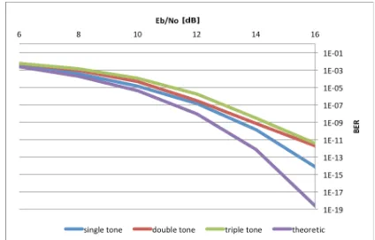
Fig. 15 shows the simulation results using the above parameters. The figure compares the BER vs Eb/N0 curve without jamming (indicated as "theoretical" curve, in the graph) with the curves obtained in the case of signals with one, two or three jamming tones.
The results indicate that for multi-tone jamming, the excision algorithm gives worse results than a single tone jamming. This is because, in the case of multi-tone jamming, the jamming components are normally located in different sub-bands and, consequently, more channels are suppressed by the algorithm.
[image:7.612.316.528.540.676.2]In general, a greater number of suppressed sub-bands implies a deformation of the useful signal and, therefore, the degradation of the system performance.
4.6 Excision with Swept Jamming
In the case of sweep jamming, the jammer signal moves across different sub-bands. In order to detect the jamming presence, the signal must stay inside a single channel for a time greater than the energy integration interval (see Sect. 4.4).
In addition, the system latency must be enough small to make the jamming detection time compatible with the real-time performance. Since the latency depends on the number of coefficients and the level of decomposition (for each level of decomposition a proper filter is required),
simulations are performed varying these
parameters. The number of coefficients
considered in the simulations is 4, 12, 16 and 20, while the levels of decomposition are 8 (Fig. 16), 9 (Fig. 17) and 10 (Fig. 13).
Simulation results show that for Eb/N0 = 16 dB
it is possible to obtain a BER value less than 10-8
using a db16 or db20 wavelet with 9 levels of decomposition.
[image:8.612.317.527.290.430.2]Figure 16 WPD Swept Jamming Excision Using 8 Levels Of Decomposition
Figure 17WPD Swept Jamming Excision Using 9
Levels Of Decomposition
4.7 Excision with Hop Jamming
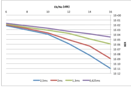
In the case of hop jamming, the length of the energy integration interval is the most relevant parameter for the performance. In this case, the integration time must be selected taking into account the hopping period. Simulations are performed considering 10 levels of decomposition and a db16 wavelet which are the optimal choice for single tone jamming (hop jamming can be considered a time variant case of single tone jamming).
Fig. 18 shows the results of simulation for different integration interval, assuming a hop period of 10 ms.
Figure 18 Hop Jamming Rejected By Db16 Wavelet Method Using 10 Levels Of Decomposition.
5. JAMMING EXCISION USING
POLYPHASE FILTER BANK
Analogously to the wavelet approach, this method removes the jamming in the transformed frequency domain. Signal is analyzed dividing its spectrum into several bands. Then the sub-bands affected by the jamming are removed while the residual bands are recombined for obtaining the output signal.
The following sections will analyze the performance of the polyphase filter bank approach for jamming excision. The contribution of the different parameters on the system performance will be also analyzed.
5.1 Length of energy integration interval
[image:8.612.88.301.360.670.2]case, a good compromise is obtained choosing the integration time equal to the delay time of the filter.
5.2 Filter order and number of channels
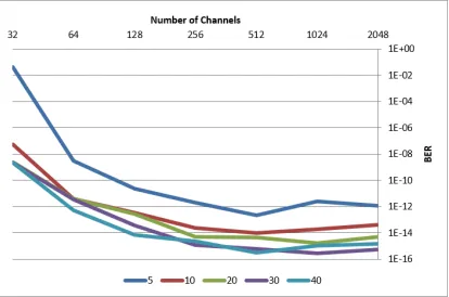
The filter order and the number of channels are two important parameters for the characterization of filter bank approach. In fact, the selectivity of the prototype filter increases with the filter order. The number of channels also plays an important role on the jamming excision performance, especially for tone, multi-tone and hop jamming.
In Fig. 19 the BERperformance vs. the number of
[image:9.612.315.528.48.231.2]sub-band is shown, assuming an Eb/N0= 16dB. In the same graph, the effect of prototype filter selectivity is also analyzed. It is expressed in terms of number of taps for each sub filter. Also in this case, a more selective filter reduces the degradation of the output signal.
Figure 19 BER Of A DSSS Signal With Single Tone Jamming Rejected By Filter Bank Method.
5.3 Excision with Multi-tone Jamming
For multi-tone jamming we can repeat the considerations developed for the wavelet-based excision. In this case, the excision algorithm results are worse than those of a single tone jamming. In fact, in this case jamming components are normally located in different sub-bands and consequently more channels are removed by the algorithm.
Fig. 20 shows the results for two-tones jamming excision.
Figure 20 BER Of A DSSS Signal With Double Tone Jamming Rejected By Filter Bank Method.
5.4 Excision with Hop and Swept Jamming
Hop and swept jamming are characterized by non-stationary spectrum. Experiments show that the increase of the number of coefficients and the number of channels improves the algorithm performance. The best BER values are obtained considering 2048 channels and a number of sub-filter coefficients between 10 and 50. In the
simulations, the obtained BER was about of 10-15,
for the swept jamming, and was about 10-11 for the
hop jamming.
6. CONCLUSIONS
In this paper two different methods for jamming excision has been analyzed and compared. The two methods are based on the wavelet transform and the perfect reconstruction filter banks, respectively. The analysis has been performed in order to evaluate the effectiveness of the two methods and the impact of the different parameters on the excision performance, for different types of jamming.
Experimental results confirm that both the methods can be used to mitigate the effects of tone and multi-tone jamming, pulse jamming, hop jamming and swept jamming. The present work shows that in both cases the excision performance is greatly dependent on the parameters used for the design of the two structures Each parameter has a different effect on the system behavior.
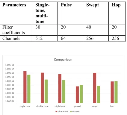
[image:9.612.92.299.352.489.2]obtained considering an Eb/N0= 16dB. The graph shows that, for the parameters in Tab. 2 and Tab. 3, the filter bank approach outperforms the wavelet based approach for almost all the types of jamming, excluding the hop jamming.
In general, the performance of the approach based on wavelet transforms is better when non-stationary jamming is present (as the hopping jamming). In fact, the time-frequency localization of wavelet functions makes them a good basis for expanding non-stationary signals. On the other hand, the use of sinusoidal function basis (as is the case of filter bank approach) is more suitable for representing stationary signals.
The above simulation results allow to reach the objectives described in the introduction. Using these results the designers will be able to select the more suitable method for a given jamming type. Moreover, the above analysis will support the trade-off of the different parameters.
[image:10.612.86.295.393.455.2]In order to give a more powerful design tool, the authors have started a new study that will provide a comparison of the two methods also in terms of hardware complexity.
Table 2. Chosen Parameters For Wavelet Method
Parameters Single-tone, multi-tone and pulse
Swept Hop
Wavelet db20 db16 db16
N 10 9 10
[image:10.612.86.298.482.674.2]Time 896µs 358,4µs 716,8µs
Table 3. Chosen Parameters For Filter Bank Method
Parameters Single-tone, multi-tone
Pulse Swept Hop
Filter coefficients
30 20 40 20
Channels 512 64 256 256
Figure 21. Jamming Excision Comparison For Wavelet And Filter Bank Methods.
REFRENCES:
[1] A. Yousaf and A. Loan, “Effect of jamming technique on the performance of Direct
Sequence Spread Spectrum Modem”,
Advanced Communication Technology
(ICACT) 2011, pp 874-877
[2] V.Thyagarajan, S.Kaja Mohideen.
“Strengthening Anti Jam GPS System with
Adaptive Phase Only Nulling Using
Evolutionary Algorithms”, Journal of
Theoretical and Applied Information
Technology 20th March 2014. Vol. 61 No.2
[3] L. Simone, F. Caselli, “Adaptive Interference Rejection Filtering in On-Board Direct-Sequence / Spread-Spectrum Transponder for TT&C Applications: Analysis, Simulation &
Breadboard Test Results”, AHS’08. NASA/ESA
Conference on, 2008 pp. 62-69
[4] R. Suleesathiru; L. F. Chaparro, “Jammer excision in spread spectrum using discrete evolutionary-Hough transform and singular value decomposition Statistical Signal and
Array Processing”, Statistical Signal and
Array Processing, Proceedings of the Tenth
IEEE Workshop on 2000.
[5] Ye Yuan Wen-bo Mei Yi-qian Li, “Chirp-Like Jammer Excision in DSSS Communication Systems Using EMD Based Radon Wigner
Distribution”, International Conference on
Wireless Communications, Networking and Mobile Computing 2009
[6] L. Simone, F. Caselli, “Wavelet packet transform processing for interference excision in TT&C Spread-Spectrum Transponder"
Signal Processing for Space Communication, 10th International Workshop on, 2008 pp. 1-6
[7] Moon, W., Park, S., Lee, J., Im, S., “Performance evaluation on a polyphase filter bank structure based anti-jamming system”,
IEEE Digital Signal Processing and Signal Processing Education Meeting (DSP/SPE) 2013
[8] Dai, L., Gao, M. “Application of uniform DFT filter bank in radar jamming system”
Journal of Systems Engineering and
Electronics Volume 17, Issue 3, September Pages 527-530 2006
IET Signal Processing Volume 9, Issue 5, 1
July, Pages 457-464 2015.
[10] L. Musumeci and F. Dovis. “Use of the Wavelet Transform for Interference Detection and Mitigation in Global Navigation Satellite
Systems” International Journal of Navigation
and Observation Volume , Article ID 262186, 14 pages 2014
[11] L. Musumeci and F. Dovis. “Use of Wavelet
transforms for interference mitigation”
Localization and GNSS International
Conference on 29-30 June 2011
[12] L. Musumeci and F. Dovis. “A Comparative Analysis of Adaptive Notch Filtering and
Wavelet Mitigation Against Jammers
Interference” Proceedings of the 28th
International Technical Meeting of The Satellite Division of the Institute of Navigation 2015
[13] Le Dai, Meiguo Gao “Application of uniform DFT filter bank in radar jamming system”
Journal of Systems Engineering and
Electronics Volume 17, Issue 3 2006
[14] GPS World staff “Combat jamming with adaptive notch filtering or wavelet mitigation:
a comparison”
http://gpsworld.com/combat- jamming-with-adaptive-notch-filtering-or-wavelet-mitigation-a-comparison
[15] S. K. Mitra, “Digital signal Processing - A
computer based approach” 4e, 2013. Mc Graw
Hill Version February 7, 2017
[16] R.E. Crochiere,L. R. Rabiner Multirate
“Signal Processing”, Prentice-Hall,1983. pp
311-312
[17] S. Mallat, A “Wavelet Tour of Signal
Processing”, 2nd ed, Accademic Press, 1999.
[18] P. Vaidyanathan. Multirate “Digital Filters, Filter Banks, Polyphase Networks, and
Applications: A Tutorial” proceeding of the
IEEE, Vol. 78, N. 1, January 1990
[19] J. G. Proakis, “Digital Communications”, 2001,4th ed, McGraw-Hill, pp. 698-709 [20] W. H. Tranter, K. L. Kosbar and K. S.
Shanmugan, “Principles of Communication
Systems Simulation with Wireless