International Journal of Emerging Technology and Advanced Engineering
Website: www.ijetae.com (ISSN 2250-2459, ISO 9001:2008 Certified Journal, Volume 2, Issue 12, December 2012)
614
FPGA based Implementation of Iris Recognition
Bethuna
1, Dr. Srinivsulu Tadisetty
2, Praveena Yadav
3 1Student(M tech), 2Professor, GNIT, JNTUH, Hyderabad3Senior Technical Officer, ECIL, Hyderabad
Abstract— Security plays a vital role in present day scenario where identity fraud and terrorism possesses great threat. Biometrics is emerging as a technology that provides a higher level of security, efficiency and convenience than traditional ID or password methods for user authentication. Human has many biometric features such as fingerprint, hand geometry, gait, face, voice and iris. Among these Iris has very special structure which makes the identification highly accurate. However, the iris recognition algorithms are currently implemented on general purpose sequential processing systems, such as generic central processing units (CPUs). Parallel processing alternative using field-programmable gate arrays (FPGAs), offers an opportunity to increase speed of the resulting system. Most time consuming part of Iris recognition algorithm is implemented using Verilog HDL. Matching part of the iris recognition algorithm has been implemented targeting low-cost Spartan 3AN FPGA, achieving significant reduction in execution time when compared with a conventional software based applications. Keywords— Iris recognition, FPGA, parallel processing, Hamming distance.
I. INTRODUCTION
Biometrics is the science of recognizing the identity of an individual based on physiological and behavioural characteristics of the subject. Biometric authentication has evolved from the disadvantages of traditional means of authentication. The primary advantage of biometrics over token based and knowledge based approaches is that, it cannot be misplaced, forgotten or stolen. Also it is very difficult to spoof biometric traits as the person to be authenticated needs to be physically present. Human has many biometric features such as fingerprint, hand geometry, gait, face, voice and iris. Among these Iris recognition is more accurate and reliable due to the stability of the iris texture patterns with age and health conditions. [image:1.612.338.570.211.366.2]
Iris is the colored part between pupil and sclera (white part of the eye) which lies behind carnia and immune to external environment. The patterns within the iris are very unique to each person, and even the left eye is unique in comparison to the right eye. Irises form in the first year of human life and remain unchanged over the lifetime. These properties of the iris make it superior to other biometric modalities for automatic authentication systems.
FIG I: HUMAN EYE[8]
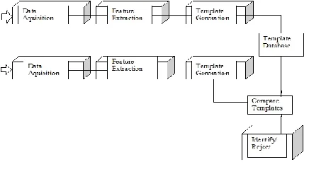
A generic biometric system (FIG II) operates by taking an input from the user, preprocessing the signal to denoise it to find the region of interest, extracting features, and authenticating an individual based on the result of comparison .
Biometric authentication processes are composed of two phases. In the first phase the database is created where the feature sets which describes each individual is stored. In the second phase the extracted feature sets are compared with the feature templates stored in the database to find a match. Biometric authentications can be of two types, Identification and Verfication.
Identification is a task where the a submitted biometric sample is compared to all the templates in a database to find a match.
Verification is a process where the biometric system attempts to confirm an individual’s claimed identity by comparing a submitted sample to one or more previously enrolled templates.
International Journal of Emerging Technology and Advanced Engineering
Website: www.ijetae.com (ISSN 2250-2459, ISO 9001:2008 Certified Journal, Volume 2, Issue 12, December 2012)
[image:2.612.60.278.134.257.2]615
FIG II: GENERIC BIOMETRIC SYSTEM
Generally the implementation of biometric algorithms is carried out using high-performance microprocessors working at clock frequencies in the GHz range. However, such software implementations could restrict the application of biometrics to specific markets because of the microprocessor cost. Devices available in the low-cost consumer market are generally too slow for applications requiring intensive computations. With advances in the VLSI (Very Large Scale Integrated) technology hardware implementation has become an attractive alternative. Implementing complex computation tasks on hardware and by exploiting parallelism and pipelining in algorithms yield significant reduction in execution times[3].
Implementing iris biometric algorithm on
reconfigurable hardware minimizes the time-to market cost, enables rapid prototyping of complex algorithms and simplifies debugging and verification[5]. Therefore, FPGAs are an ideal choice for implementation of real time iris recognition algorithms. The purpose of this paper is to describe the implementation of iris matching using verilog HDL targeting low-cost Spartan-3AN FPGA.
II. HISTORY
The idea of using the iris as a biometric is over 100 years old . However, the idea of automating iris recognition is more recent. In 1985, two Ophtholmologists Dr. Leonard Flom and Dr. Aran Safir proposed the concept that no two irises are alike, even in twins, thus making them a good biometric. This belief was based on their clinical experience where they observed the distinctive features of irises including the ―many collagenous fibres, contraction furrows, coronas, crypts, colour, serpentine vasculature, striations, freckles, rifts and pits‖. After researching and documenting the potential use of irises as a means of identifying people they were awarded a patent for an unimplemented conceptual design of an automated iris biometric system in 1987.
They suggest using pattern recognition tools, including difference operators, edge detection algorithms, and the Hough transform, to extract iris descriptors. They also suggested that a description of an individual’s iris could be stored on a credit card or identification card to support a verification task. They approached Dr. John Daugman, then a professor at Harward university to develop the algorithm. By 1994 the algorithms had been developed.
This work still remains valuable because it provides solutions for each part of the system. The algorithm gives the accuracy of 99.9%. Most systems implemented today are based on his work. They are based on Gabor wavelet analysis [4] in order to extract iris image features. Convolution of image is performed with complex Gabor filters. As a product of this operation, phasors (complex coefficients) are computed. After Daugman’s algorithm, another important work is Wildes’.
Wildes has made use of an isotropic band-pass decomposition derived from application of Laplacian of Gaussian filters to the image data [5]. The Wildes system explicitly models the upper and lower eyelids with parabolic arcs whereas Daugman excludes the upper and the lower portions of the image. In matching two irises, Daugman’s approach involves computation of the normalized Hamming distance between iris codes, whereas Wildes applies a Laplacian of Gaussian filter at multiple scales to produce a template and computes the normalized correlation as a similarity measure.
III. IRIS RECOGNITION ALGORITHM
The implemented iris recognition system is based on the algorithm developed by Dr. Daugman. Iris recognition process is basically divided into five steps.
Image acquisition
Iris Segmentation
Normalization
Encoding
Matching
A. Image acquisition
This step is one of the most important and deciding factors for obtaining a good result. A good and clear image eliminates the process of noise removal and also helps in avoiding errors in calculation. In near Infrared wavelengths, even darkly pigmented irises reveal rich and complex features.
International Journal of Emerging Technology and Advanced Engineering
Website: www.ijetae.com (ISSN 2250-2459, ISO 9001:2008 Certified Journal, Volume 2, Issue 12, December 2012)
616 B. Iris Segmentation
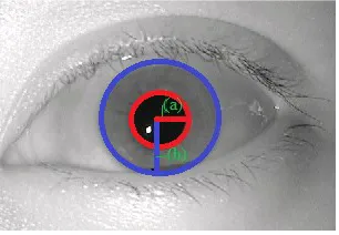
The iris inner and outer boundaries are located by finding the edge image using the Canny edge detector. Hough transform is used to localize the iris[2].
FIG III:(A)PUPIL RADIUS (B)IRIS RADIUS
C. Normalization
Different circles with increasing radius and angle are drawn starting from the pupil centre till it reaches near the iris coordinates. In our case 8 concentric circles are drawn and each subdivided into 256 sectors[4]. Then iris is unwrapped by converting into its polar equivalent. It is done using Daugman’s Rubber sheet model[1].
x = c(x) − r *sin(θ )
y = c( y) + r *cos(θ ) --- (1)
where c(x, y) denotes centre coordinates, (x, y) denotes coordinates of the image, θ is the angle from horizontal axis with the range (0-360°) and r denotes the radius with the range (0-1).
For every pixel in the iris, an equivalent position is found out on polar axes.
FIG IV:DAUGMAN’S RUBBER SHEET MODEL[1]
D. Encoding
The final process is the generation of the iris code is encoding the unwrapped iris. The Gabor filters are used in this step. The iris code is formed by assigning 2 elements for each pixel of the image. Each element assigned a value 1 or 0 depending on the sign + or – of the real and imaginary parts of the complex plane.
[image:3.612.337.551.177.288.2]Noise bits are assigned to those elements whose magnitude is very small and combined with the noisy part obtained from normalization. In this way we got a code of 2048 bits[1][7].
FIG V: PHASE QUANTISATION
---(2)
Where, h{Re, Im} has the real and imaginary part, each having the value 1 or 0, depending on which quadrant it lies
.
E. Code Matching
Comparison of the bit patterns generated is done to check if the two irises belong to the same person. Calculation of Hamming Distance (HD) is done for this comparison. HD is a fractional measure of the number of bits disagreeing between two binary patterns[4][7].
---(3)
IV. ADOPTED ARCHITECTURE
[image:3.612.99.252.182.288.2] [image:3.612.78.247.518.571.2]International Journal of Emerging Technology and Advanced Engineering
Website: www.ijetae.com (ISSN 2250-2459, ISO 9001:2008 Certified Journal, Volume 2, Issue 12, December 2012)
617 Live template is compared with the templates in the database by calculating hamming distance between them. Since orientation of iris changes time to time best match is found by shifting the data template 2 bits left and then performs comparision operation again with the live template.
If match found search will be stopped after generating the result else search will continue for the entire database.Result can be displyed on monitor or through LED. Matching module has the internal structure as follows:
Memory Module
HD modules
Adder tree
Comparator and display
FIG VI:SYSTEM ARCHITECTURE
Iris template database is created and stored in ROM. Live template will be stored in RAM. Live template will be compared with each template in the datbase by calculating hamming distance. For perfectly matched templates hamming distance will be 0.
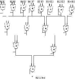
Each HD module will receive 128 bit inputs from the two templates to be compared and calculates hamming distance between them. Output from each HD module will be of 8 bits length. Outputs from all HD modules will be added together in adder tree to get final hamming distance between live and database templates.
In order to reduce the carry delay in parellel adders tree like structure can be adopted. It has 4 levels of adders. In first level each adder will add outputs from HD modules. Number of bits to be added in each level is determined by maximum possible values of HD inputs at first level.
Since maximum possible value is 10000000, maximum possible sums of first level are determined length of next level adders are calculated accordingly.
1st level-8bit adders
2nd level-9bit adders
3rd level-10 bit adders
4th level – 11 bit adder
[image:4.612.376.528.270.434.2]The final HD value will be of 12 bits length and is compared with the predetermined threashold value. Threashold is set to 30%. For matched irises HD should be less than threashold(HD<threashold).
FIG VII: ADDER TREE
V. IMPLEMENTATION
[image:4.612.64.276.326.491.2]International Journal of Emerging Technology and Advanced Engineering
Website: www.ijetae.com (ISSN 2250-2459, ISO 9001:2008 Certified Journal, Volume 2, Issue 12, December 2012)
618 VI. CONCLUSIONS& FUTURE SCOPE
Low cost and fast execution are important parameters for real time authentication systems. The main purpose of the work described in this paper is to implement most time consuming part of iris recognition algorithm on a low-cost FPGA. The proposed design is implemented using verilog HDL. This design is suitable for small low cost applications.
Future improvements in the system can be done by implementing the feaure extraction task on hardware which can further reduce the authentication time. Instead of using Matlab we can use Microblaze soft core processor and can implement the iris localization and iris normalization in C. By this we can implement entire system on single chip.
FIG VII: RTL OF MATCHING MODULE
FIG VI: SIMULATION RESULTS OF MATCHING MODULE
FIG VII:SIMULATION RESULT OF HAMMING DISTANCE
REFERENCES
[1] Daugman, J. G.: ―How iris recognition works‖ IEEE Trans. Circuits Syst. Video Technology, vol. 14, no. 1, pp. 21-30, Jan. 2004.
[2] P. Wildes, S. C. Hsu R. J. Kolczynski . R. Matey J. C. Asmuth and S. E. McBride.: “Automated, noninvasive iris recognition system and method.” U.S. Patent, No. 5,572,596.
[3] Ryan N. Rakvic, Brandley J. Ulis, Randy P. Broussard, Robert W. Ives and Neil Steiner.: ―Parellelizing Iris Recognition‖, IEEE Transactions on Information Forensics and Security, Vol. 4, No. 4, December 2009. [4] Daugman, J. G.: ―The importance of being random: statistical principles of iris recognition,‖ Pattern Recognition 36 p279-291, 2003. [5] ZHOU Hu-Lin, XIE Mei: ―Iris Biometric Processor Enhanced Module FPGA based Design‖ 2010 Second International Conference on Computer Modeling and Simulation.
[6] http://pesona.mmu.edu.my/~ccteo/
[7] Daugman, J. G.: ―Probing the uniqueness and randomness of IrisCodes: Results from 200 billion iris pair comparisons,‖ Proceedings of the IEEE, vol. 94, no. 11, Nov. 2006, pp 1927-1935.
[8] http://en.wikipedia.org/wiki/File:Eye_iris.jpg
[9]―CASIA Iris Image Database,‖ Inst. of Automation, Chinese Academy of Sciences, http://www.sinobiometrics.com, 2004.
![FIG I: HUMAN EYE[8]](https://thumb-us.123doks.com/thumbv2/123dok_us/8747267.891081/1.612.338.570.211.366/fig-i-human-eye.webp)