COLLAPSIBILITY BEHAVIOUR OF ABS P400 AND PMMA USED AS SACRIFICIAL PATTERN IN DIRECT INVESTMENT CASTING PROCESS
MUHAMMAD SHAZWAN BIN SHUKRI
A thesis is submitted in
fulfillment of the requirement for the award of the Degree of Master of Mechanical Engineering
Faculty of Mechanical and Manufacturing Engineering Universiti Tun Hussein Onn Malaysia
SPECIAL GRATITUDES TO:
MY BELOVED MOTHER, Imilah @ Jamilah Binti Hasan @ Hassan
For her love, patience and support in my whole life
MY HONOURED SUPERVISOR, Assoc. Prof Dr. Mustaffa Bin Hj. Ibrahim
For his generosity, advices, trust, support, patience and kindly guide me to complete this research
MY RESPECTED CO-SUPERVISOR, Dr. Omar Mohd Faizan bin Marwah
For his guidance, advices and technical support
MY LOVELY FIANCE, Adiba Rhaodah Andsaler
For her advices, moral support, patience and encouragement in this study
AND ALL MY COLLEAGUES,
For their help and support direct and indirectly, effort and motivation in this study
ACKNOWLEDGEMENT
I would like to express my sincere gratitude to all those who gave me the opportunity and possibility to finish this thesis and my research especially to my beloved supervisor, Assoc. Prof Dr. Mustaffa Bin Hj. Ibrahim who has given advises and trusting me for this given title and kindly guide me to complete this research. Besides, a special thanks to my co-supervisor, Dr. Omar Mohd Faizan bin Marwah who has given motivation and support especially in the aspect of analysis work and thesis writing advises.
I would like to thanks to the Ministry of Education for funding this research under the Fundamental Research Grant Scheme (FRGS) vot 1423.
I would like to illustrate my sincere appreciation to those who had contributed directly and indirectly towards to the successful of this research project. I am deeply indebted to all additive manufacturing staff from Faculty of Mechanical and Manufacturing Engineering who had given very kind helps and invaluable guidance especially in experimental works and testing materials.
Moreover, I would like to give my special thanks to my fiance, Miss Adiba Rhaodah Andsaler who had fully supporting, gave advices, and encouraged me all the time throughout the whole process of this research work.
ABSTRACT
ABSTRAK
TABLE OF CONTENT
TITLE i
ABSTRACT v
ABSTRAK vi
TABLE OF CONTENT vii
LIST OF TABLES x
LIST OF FIGURES xi
LIST OF SYMBOL AND ABBREVIATION xiv
CHAPTER 1 INTRODUCTION 1.1 Research Background. 1 1.2 Problem Statement 3 1.3 Objectives of the Study 5 1.4 Scope of the Study 5 1.5 Significance of Study 6 1.6 Summary 6 CHAPTER 2 LITERATURE REVIEW 2.1 Introduction 7
2.2 Conventional Investment Casting 8 2.2.1 Constraints of Investment Casting Process 9
2.3 Additive Manufacturing Technology 11 2.3.1 Classification of Additive Manufacturing 13 2.3.2 Potential Growth of Additive Manufacturing 15 2.3.3 Personal Desktop 3D Printer 17 2.4 Fused Filament Fabrication Technique 20 2.4.1 Material Characteristic for Fused Filament Fabrication Process 21
2.5 Jetting Technique 24 2.5.1 Material Characteristic for Jetting Process 26
2.5.2 Properties of PMMA Material 28
2.6 Application of Additive Manufacturing Process
in Investment Casting 29
2.6.1 Solid Based Materials in Direct Investment Casting 31 2.6.2 Liquid Based Materials in Direct Investment Casting 37 2.7 Factors Influences the Cracking of Ceramic Shell Mould 40
2.7.1 Glass Transition Temperature 40
2.7.2 Modulus of Rupture 41
2.7.3 Coefficient of Thermal Expansion 42
2.7.4 Strain and Stress 43
2.8 Previous Studies on The Applications of AM in IC Process 45
2.9 Summary 47
CHAPTER 3 METHODOLOGY
3.1 Introduction 48
3.2 AM Pattern Design 50
3.3 Different Built Internal Pattern Structure 51
3.4 Fabrication of AM Patterns 53
3.4.1 Fabrication of FFF Pattern 53
3.4.2 Fabrication of Polyjet Pattern 55
3.5 Application of Strain Gauge 57
3.5.1 High Temperature Strain Gauge 58
3.5.2 Portable Data Logger 61
3.6 Dimensional Accuracy Measurement 63
3.7 Surface Roughness Measurement 65
3.8 Experimental of Direct Investment Casting 67
3.8.1 Thermogravimetric Analysis (TGA) 67
3.8.2 Thermal Expansion 69
3.8.3 Slurry and Stucco of AM Pattern 70
3.8.4 Burnout of Patterns and Casting Alloy Process 72
CHAPTER 4 RESULTS AND DISCUSSION
4.1 Introduction 77
4.2 Evaluation of Fabricated Sacrificial Patterns 78 4.2.1 Dimensional Accuracy Analysis 78 4.2.2 Surface Roughness Analysis 81
4.3 Strain Analysis of Sacrificial Patterns and Ceramic Shell 84 4.3.1 Strain Analysis of ABS Sacrificial Pattern and Ceramic Shell 84 4.3.2 Strain Analysis of PMMA Sacrificial Pattern and Ceramic Shell 88 4.4 Evaluation of Sacrificial Patterns in Direct Investment Casting Process 91 4.4.1 Thermogravimetric Analysis 91
4.4.2 Thermal Expansion of Materials 93 4.4.3 Collapsibility Analysis of Sacrificial Patterns 95 4.5 Casting Parts Evaluation 98 4.5.1 Shrinkage Measurement Analysis 98 4.5.2 Surface Roughness Analysis 99
4.5.3 Defects of the LM6 Casting 101
4.6 Summary 103
CHAPTER 5 CONCLUSION AND RECOMMENDATION 5.1 Introduction 105
5.2 Recommendation for Future Work 107
REFERENCES 108
APPENDIX A 113
APPENDIX B 115
APPENDIX C 119
LIST OF TABLES
2.1 Classification of AM process 14
2.2 Thermal and Mechanical properties of ABS P400 24 2.3 Thermal and Mechanical properties of PMMA 3D printer 28 2.4 Summary of previous studies of AM in IC process 45
3.1 Machine specification of FFF 55
3.2 Specification details of Polyjet machine 57 3.3 The references of dimension accuracy measurement 64 3.4 The surface roughness test for X and Y directions 66 3.5 The parameters of slurry and stuccoing process 71
3.6 Ceramic shell procedures 71
4.1 Shrinkage deviation comparison 80
LIST OF FIGURES
2.1 Overview of Investment Casting process 9
2.2 The total IC process lead time 10
2.3 AM systems in various sectors in 2013 15
2.4 The AM systems deployment by applications
in 2013 16
2.5 Personal 3D printer by Makerbot industries 17
2.6 Market growth of personal 3D printer 18
2.7 Global 3D printing market estimates and forecast 19
2.8 Schematic of Fused Filament Fabrication 21
2.9 Chemical structure of ABS polymer 22
2.10 ABS P400 filament (3D PRINTING, 2014) 23
2.11 Schematic process of Polyjet desktop 3D printer 25
2.12 Chemical structure of PMMA material 27
2.13 Catridge of PMMA Materials 27
2.14 Investment casting with AM approaches 30
2.15 A casting parts using ABS as sacrificial pattern 33 2.16 A hot water dewaxing process for ABS pattern 34
2.17 Aluminium casting of impeller 36
2.18 Three levels for QuickCast 2.0 offset hexagon 38
2.19 Shell cracking during heating 39
2.20 New structure after auto-claving 39
2.21 A graph of thermal expansion 41
2.22 Stress and strain slope 42
2.23 The comparison between compression and tension 43
3.1 Methodology flowchart 49
3.3 Different internal pattern structure for ABS P400
and PMMA materials 52
3.4 The fabricated internal patterns 52
3.5 Portable 3D printer Odyssey X2 machine 54
3.6 Portable 3D printer Object 30 Pro 56
3.7 Structures of foil strain gauge` 58
3.8 Location of applied strain gauge on pattern 60 3.9 Location of applied Strain gauge on ceramic shell 61
3.10 Portable data logger 62
3.11 Part location of dimensional accuracy testing 63
3.12 Flexible measuring machine (FMM) 64
3.13 Part of surface roughness testing 65
3.14 Surface roughness measurement device. 66
3.15 The TGA furnace machine 68
3.16 TGA data result 68
3.17 Orthon dilatometer 69
3.18 Ceramic shell mould during burnout process 73 3.19 Firing ceramic mould and removal of AM pattern 74
3.20 Melting process of the Alloy LM6 75
3.21 Pouring of molten LM6 process 75
3.22 The knockout process for final product 76
4.1 Dimensional accuracy of different internal
Structures for ABS P400 79
4.2 Dimensional accuracy of different internal
Structures for PMMA 79
4.3 Surface roughness of different internal
structures for ABS P400 82
4.4 Surface roughness of different internal
structures for PMMA 82
4.5 Strain on ABS patterns for different internal structures 86 4.6 Strain on ABS ceramic shell for different internal structures 88 4.7 Strain on PMMA patterns for different internal structures 89 4.8 Strain on PMMA ceramic shell for different internal
4.9 TGA of AM materials 92 4.10 Linear thermal expansion of ABS material 94 4.11 Linear thermal expansion of PMMA material 94 4.12 Collapsibility of ABS patterns during burnout process 96 4.13 Collapsibility of PMMA patterns during burnout process 97
4.14 The comparison of the parts shrinkage 99
4.15 The comparison of the surface roughness 100 4.16 The rear surface of half cylindrical shape of casting products 101 4.17 The bottom surface of casting products 101 4.18 The front surface of the casting parts 102 4.19 The upper surface of half cylindrical shape of
LIST OF SYMBOL AND ABBREVIATION
α - Type I error (α risk)
β - parameter
°C - Degree celcius
µm - Micrometer
K - kelvin
ΔL - Change length in speciment ΔT - Temperature change during test ΔX - Dimensional deviation
3DP 3D Printing
ABS Acrylonitrile butadiene styrene
AM Additive manufacturing
ASTM American standard testing method CAD Computer aided design
CMM Coordinate measuring machine CTE Coefficient thermal expansion DIC Direct investment casting
DA Dimensional accuracies
FDM Fused deposition modelling FFF Fused filament fabrication IC Investment casting
ISO International standard organization
LM Layer manufacturing
LT Layer thickness
LOM Laminated object manufacturing
MJM Multijet modelling
MM Model maker
PMMA Poly methyl methacrylate Ra Roughness accuracy
RP Rapid prototyping
RM Rapid manufacturing
RIC Rapid investment casting
RT Rapid tooling
Rv Void ratio
SR Surface roughness
SLA Stereolithography
SLS Selective laser sintering STL Stereolithography file Tg Glass transition temperature
CHAPTER 1
INTRODUCTION
1.1 Research Background
Investment Casting (IC) is considered as a feasible method to substitute conventional manufacturing process regarding its advantages in producing near net shape of metal with economical of mass production. Conventional method of IC using traditional wax material as a sacrificial pattern has been preferred as the expendable material which can be reused after dewaxing process as well as reducing the materials cost. Despites its advantage in reducing the cost, there is a limitation in which producing the precision casting of metal whereas the wax material easily breaks and warps due to its brittleness properties. Thus, for requirement in precision thin wall casting which is need to be dipped into the slurry coating to develop deposition of ceramic shell molds, it is not recommended. In addition, using the wax as sacrificial pattern has encountered major problem such as slow processing development of new pattern mold in which results in expensive cost and longer total lead time process (Dickens
et al., 1995). Hence, it is not suitable for low volume casting production whereby longer lead time and high cost are the main concern factors. For instance, the high
Therefore, Additive Manufacturing (AM) has inspired many manufacture industries in providing variations of perspective in IC process. This technology
benefits the designer to produce a 3D part directly from the Computer-Aided Design (CAD) data more frequently without additional lead time. The fabricated prototype patterns are used for evaluation assessment with the valuable impact of perception especially for tool making or early optimization of concept designs. The ability of producing smooth surface, better dimensional accuracy and complexity shape have taken AM technologies one step ahead from wax pattern. Henceforward, IC industry has taken these advantages of using AM technologies to produce the sacrificial pattern either by direct or indirect approaches.
Concurrently, there are several types of AM techniques that offer robustness in terms of patterns fabricated in which to be employed in IC process. Major techniques of AM such as Stereolithography (SLA), Selective Laser Sintering (SLS), Fused Deposition Modeling (FDM), Laminated Object Manufacturing (LOM), Multijet Modeling (MJM) and Three Dimensional Printing (3D-Printer) have been explored its achievability in producing sacrificial patterns (Marwah et al., 2012). Generally, utilization of AM parts in interchange of the conventional wax pattern has beneficial in substantial lead time, effective cost, excellence quality and turn into essential tool for fabricating new product design. Subsequently, implication of AM has speed up the lead times of production from virtual to physical prototyping.
Regarding its proficiency to produce pattern, AM has a few potential issues that many researchers encountered since years ago. The issues regarding the quality of the pattern are shrinkage and wrapping which need a full consideration. In this case, early optimization of parameters should be implant in order to enhance the quality of the fabricated AM part (Sabau, 2007).
technology which is capable of producing physical pattern which has precision dimension as well as smooth and transparent surface is Polyjet 3D Printer system.
This system works on concept of similar to inkjet printing, but instead of jetting drops of ink onto paper, PolyJet 3D Printers jet layers of curable liquid photopolymer onto a build tray. Nevertheless, there are fewer reports regarding the quality of end product produce by portable 3D machines and the feasibility to be used as sacrificial pattern in IC process. Hence, in this study, it is essential to determine the competency of printed pattern by portable 3D machines to be used as sacrificial pattern in IC process.
On the other hand, occurrence of cracking of shell mold is major problem for non-wax materials such as Acrylonitrile Butadine Styrene (ABS) from FDM. Consequently, the reconstruction of internal pattern structures have been effectively and aggressively studies to solve the issue regarding the cracking of ceramic shell moulds (Norouzi et al., 2009). Stresses induced by pattern expansion during burnout process are major problems resulting in shell cracking. In addition, most of researcher focused on different internal structure patterns especially on Stereolithography (SLA) process. Thus, less reports regarding the materials used by portable 3D printer based. Besides, the Coefficient of Thermal Expansion (CTE) is one of the major issue need to be fully understand and study in order to reduce the effects of shell cracking (Wang et al., 2010). Furthermore, the glass transition temperature (Tg) also is comprehensive in determining the cracking of the ceramic shell molds and it is significant than CTE of plastic materials (Wang & Shih, 2010).
1.2 Problem statement
downside of conventional wax process essentially required die making for processing the patterns in which contributed to the higher cost and longer lead time and makes
the method unsustainable.
Many studies have been conducted to substitute the conventional method by implanting the AM technology in IC process. However, most of the studies have circulated on the feasibility of the high-end AM machine such as FDM, SLA, SLS and MJM using different materials to substitute wax pattern as sacrificial pattern in IC process. There is less reports regarding the possibility of portable AM machine to fabricate as sacrificial pattern for IC process. In addition, there is also less report regarding the study of comparison between ABS P400 and PMMA based materials pattern fabricated by portable FFF technique and Poly Jetting technique respectively. The issue such as staircase effect is the main reason that affected the quality of pattern made by AM technique. This issue indirectly affect the quality of casting parts such as dimensional accuracy and surface roughness and need to be addressed continuously (Cheah et al., 2005). Moreover, there is less report regarding the quality of part produce by portable AM machine in terms of dimensional accuracy and surface roughness that associated with IC process.
For the non-wax pattern applicable in IC process, it revealed that ceramic shell cracks due to excessive thermal expansions, incomplete collapsibility of pattern during burnout, residual ash and poor surface finish. Most of AM materials used for
1.3 Objectives of the Study
The objectives of this study are as follows:
a) To study the dimensional accuracy and surface roughness of ABS P400 and PMMA patterns made by portable AM machines that used in direct IC process.
b) To investigate the three different internal structures which are hollow, square and hexagon patterns collapsibility in IC process.
c) To analyse the rate of shell cracking during burnout process.
1.4 Scope of the Study
The accomplishments of study based on several scopes such as:
a) The fabrication of three different internal structures such as hollow, square and hexagon patterns for ABS P400 material using portable FFF 3D printer (Odyssey X2) and PMMA material using Polyjet 3D printer desktop (Object 30 Pro).
b) The three different internal structures of fabricated AM parts were evaluated including dimensional accuracy and surface roughness.
c) By using TGA and DTA to determine the thermal properties.
d) Feasibility of strain gauge for detecting the strain induce on the patterns and the ceramic shell moulds.
e) Screening the patterns collapsibility behaviour during the burnout process
1.5 Significance of study
Enhancement of new application, invention and adaptation on an existing design tool will boost the improvement of quality production. Therefore, the study on the pattern development of AM application by implanting patterns as direct sacrificial pattern in IC is essential as it beneficial in elimination of hard tooling. Diversification of techniques in AM has been explored to minimize space thoroughly and able to generate diverse solutions in IC process. Intensification of AM technique currently pays attention to portable 3D Printer techniques which is currently economical. The fabrication of AM patterns in which requires high intricacy and low mass casting in IC is the key to significant reduction of total lead time and cost effective of manufacturing.
It is expected that the outcome of the study will be an abundant support to the IC manufacturer whereby 3D Printer technologies (portable FFF 3D printer and Polyjet 3D printer) are applied in production of pattern whereby it contributed to effective of metal casting parts. Therefore, direct IC routes by portable AM machines works efficiently whereby lower cost, fast fabrication of patterns as well as enhancement of quality products are the main criteria to be concerned.
1.6 Summary
This chapter presents the introduction of this study which is vital of implementing the AM method in the IC process. Besides, it also present the research background of this study whereas involved the conventional IC process, AM methods and relation of AM in IC process. Furthermore, it shortly discusses the vital problem about this
study. In addition, the significant objectives and scopes of this study were mentioned in this chapter. In the end of this chapter, it discuss about the significant of this study
CHAPTER 2
LITERATURE REVIEW
2.1 Introduction
This chapter particularizing few aspects such as potential of Investment Casting (IC)
process, disadvantage of conventional IC process, Additive manufacturing (AM) process and the feasibility of pattern produce by AM process to be used as direct sacrificial pattern in IC process. At the end of this chapter, it be a summarization of different aspects regarding the related perspective views on this study.
2.2 Conventional Investment Casting
The advancement in the nature of the industry has driven the process to be named as lost wax process whereby the physical properties of wax itself can be shaped into
anything. Since the early days of introduction of this technology, wax has been preferred as important material to be shaped according to desire end products.
The lost wax process is favored by the name of Investment Casting (IC) process whereas the process can produces high tolerance of casting, good dimensional stability as well as near net shape of end products for most metal which can be categorized as ferrous (commonly stainless steel, tool steel and carbon steel) to non-ferrous alloy (commonly aluminum, brass and copper) (Horton, 2008). IC is ideal for applications that have relatively low production quantities (10 to 10000 pieces) or rapidly changing the product designs. In addition, IC is the most familiar method of metal fabrication that has been used for several centuries.
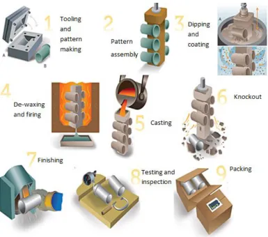
Basically, IC process requires a sacrificial wax pattern in which have same geometrical shape, design and scale as the final metal cast part. In this casting technique, a pattern, usually made of wax, is utilized in forming the inside cavity of a refractory mould. The pattern is formed by injecting the molten wax into a permanent mould of the desired shape and there by cooling it until solidification. In the ceramic shell method, the pattern is gated to a wax sprue. Then the sprue pattern are invested with ceramic slurry which is then solidified forming a mould around the wax pattern. The wax pattern is then removed from the mould by melting or burning. The subsequent refractory shell is further hardened by heating and then filled with
molten metal to produce the finished part (Bemblage & Karunakar, 2011).
medical instrument and so on (Vasconcelos et al., 2002). Figure 2.1 shows the flows of conventional IC process.
Figure 2.1: Overview of IC process (Tedds, 2013)
2.2.1 Constraints of Investment Casting Process
Despites its ability to produce an intricate design of metal part, IC suffer constrains in terms of cost and lead time. Conventional IC principally depending on the wax pattern for the fabrication of ceramic mold pattern, thus, there is necessity of tool for
pattern depending on the complexity of the design shape. In addition, conventional IC process undergoes longer total lead time due to the fabrication of injection wax
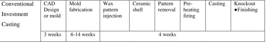
[image:24.595.102.548.195.266.2]tooling approximately 13 - 21 weeks. However, the total lead time will increase if there is flawed on the pattern tools in terms of dimensional accuracy (Jacobs, 1995). Figure 2.2 shows the total lead time for IC process.
Conventional Investment Casting CAD Design or mold Mold fabrication Wax pattern injection Ceramic shell Pattern removal Pre-heating firing
Casting Knockout ●Finishing
3 weeks 6-14 weeks 4 weeks
Total lead time = 13-21 weeks (approx.)
Figure 2.2: The total lead time of IC process
The application of IC with wax pattern has been favored by many
manufactures as it provides good surface finish and near net shape of final metal products. Nevertheless, when making a hard tooling of wax pattern it involves with high cost fabrication as well as lead time process, thus, it is not efficient for a single or low volume production (Sivadasan & Singh, 2013). These perspectives are driven by two main factors such as requirement of hard tooling and longer lead time process for tooling itself. These factors affected the chain process of IC when a low volume of production is essential. In terms of fabricating the sacrificial patterns, the hard tooling for injection moulding process is needed to produce desired sacrificial wax pattern in which leading to cost justification. Besides, mould designer commonly face few problems when undertaking some adjustment on the hard tooling pattern such as precise dimension, alteration of designs and defects on design mould. Therefore, the total time for hard tooling significantly increase due to intricacy of designs as well as modification on the designs (Ferreira et al., 2006).
whereby simultaneously applicable to the IC process. Furthermore, the substantial reduction in lead time and cost are associated with single or small quantity
production. Consequently, it influences AM technology to be employed in IC process in terms of elimination of hard tooling.
2.3 Additive Manufacturing Technology
Additive manufacturing (AM) is a standardized term approved by the International Organization for Standardization (ISO) and the American Society for Testing and Materials (ASTM) (ASTM International, 2013). Early technique of Rapid Prototyping (RP) was developed in the 1980’s for creating a prototypes parts in three
dimensional view layer by layer using Computer-Aided Design (CAD) (Wong & Hernandez, 2012). The technology was created to ensure the designer have 3D visualization of their concept design. RP is one of the earlier Additive Manufacturing (AM) processes. Historically, AM technology was used to build conceptual prototypes referring to that process as RP, a term which is still often used as a synonym to AM. Those prototypes were meant to accelerate the development phase (time-to-market) of a product and under no circumstance are comparable to the end product regarding quality, material and durability (Thymianidis et al., 2013). Scientific research was an important driver for AM technology development which boosted printer capabilities towards manufacturing functional prototypes leading inevitably to Rapid Manufacturing (RM). In addition, RM has evolved through AM
due to technological advancements defined by Pal & Ravi (2007) as the manufacture of end-use products using AM techniques. As an impact of advancements in the field of AM in the past decade, this work distinguishes RM from AM due to the use of advanced printing techniques enabled by a range of sophisticated materials which facilitates manufacturing products with long term consistency for the entire product life (Levy et al., 2003).
rapidly. In addition, the complexity and intricacy of early design concept can be built using this AM techniques.
Generally, most of the AM techniques work on the most basic concept which is the draft model design using CAD software. The model is slice from the 3D graphic model into 2D contours. This step follow by converting the CAD drawing file into the Stereolithography (STL) file whereas the STL file is common interface between CAD and AM system. Then the data must be altered to generate the commands to control the final stage of actual fabrication of the component. The final step is diverse between AM machines and depends on the basic deposition principle used in the AM machines (Sokovic & Kopac, 2006). Furthermore, it is essential to choose the appropriate building direction as it can change specifications of the object such as quality, cost and lead time.
AM techniques are standard tools in the product design and manufacturing industries (Harun et al., 2009). Moreover, AM become most essential tool for designer and shortening the required time to design the end product. This technology was employed in industrial applications to speed up the design and manufacturing process. Besides, AM approach is diverse from traditional manufacturing techniques (subtractive process) whereby, AM provides creating and object by adding materials layer by layer while in traditional ways the materials was removed by process of milling, turning, drilling, grinding and so on (Wang et al., 2010). Therefore, in terms of materials usage, AM has advantage in reducing the amount of materials to construct an object. In addition, AM significantly shortened the fabrication time of product as well as have flexibility in fabrication of intricacy shape whereby it is difficult to achieve using conventional manufacturing process (Relvas et al., 2012).
consistent tools which serve traditional manufacturing procedures (Karunakaran et al., 2000). RT has been mostly used to create injection mould but recent developments enable RT technology to be used for casting, forging and other tooling processes (Levy et al., 2003). According to Wholers Report (2013), 16% of AM processes were used for direct part production (RM), 21% for functional prototypes (RP) and 23% for tooling and metal casting patterns (RT) from which approximately 56% and 9% of process preferences were direct metal and direct polymer tooling respectively.
As the term suggest, AM has variety of names regarding its capability in producing the prototype such as Free Form Fabrication (FFF), Layer Manufacturing (LM), 3D Printing and Rapid Prototyping (RP). Currently, AM process has attracted many manufactures and researchers to collaborate regarding its potential towards future. Moreover, over last decades, advancement in the technology of AM with the consumption of laser technology has empowered variety of metals to be used in production of parts directly (Yang et al., 2009).
2.3.1 Classification of Additive Manufacturing
As demand in manufacturing process increase significantly, AM is a novel approach to solve the challenges faced by industries in terms of reduction total lead time as well as fabrication cost. The most common, and the most popular currently, is 3D Printing. AM is claimed to have triggered a third industrial revolution because the technology presents new and expanding technical, cost-effective and social impacts. Particularly, the increased accessibility to 3D printing capabilities has allowed mass customization to become more widespread in industries such as healthcare and consumer markets.
In this rapid growing industry, terminology evolves rapidly whereas the bunch of groups such as the mainstream press, the investment community, and the CAD industry recognized the technology as“3D printing” when referring to AM
Today, 3D printing accounts for only 28 % of the total manufacturing sector, but the market seems destined to explode (Wohlers, 2013). While the consumer
market is expected to be the main driver of the sector growth, there is also room for innovation in the enterprise market. Most analysts expect that more companies, from large organizations to small and medium-sized enterprises (SMEs), begins to explore the technology and unravel new business cases.
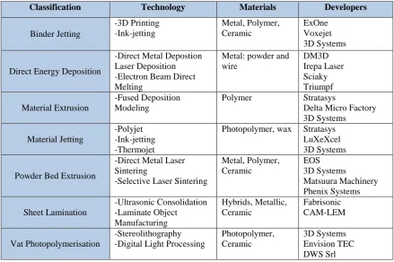
[image:28.595.91.531.399.691.2]Since the advent of mass production in the early 20th century, consumer’s demands have been met by producing large numbers of goods in significantly less time than ever before. While production time and price decreased, it reduces parallel to the expense of customization. AM makes it possible to offer customers options to personalize the products and goods they are purchasing. There are seven different additive manufacturing processes, as defined by ASTM International. Table 2.1 summarizes the seven process classifications and technologies that comprise the 3D printer market with selected market participants.
Table 2.1: Classification of AM process (ASTM, 2012)
Classification Technology Materials Developers
Binder Jetting -3D Printing -Ink-jetting Metal, Polymer, Ceramic ExOne Voxejet 3D Systems
Direct Energy Deposition
-Direct Metal Depostion Laser Deposition -Electron Beam Direct Melting
Metal: powder and wire DM3D Irepa Laser Sciaky Triumpf Material Extrusion -Fused Deposition Modeling
Polymer Stratasys
Delta Micro Factory 3D Systems
Material Jetting
-Polyjet -Ink-jetting -Thermojet
Photopolymer, wax Stratasys LuXeXcel 3D Systems
Powder Bed Extrusion
-Direct Metal Laser Sintering
-Selective Laser Sintering
Metal, Polymer, Ceramic EOS 3D Systems Matsuura Machinery Phenix Systems Sheet Lamination -Ultrasonic Consolidation -Laminate Object Manufacturing Hybrids, Metallic, Ceramic Fabrisonic CAM-LEM Vat Photopolymerisation -Stereolithography -Digital Light Processing
Photopolymer, Ceramic
2.3.2 Potential Growth of Additive Manufacturing
A recent trend on AM technology has elevated concern of many manufactures to explore the advantages of this technique. Today, evolution of 3D printer has
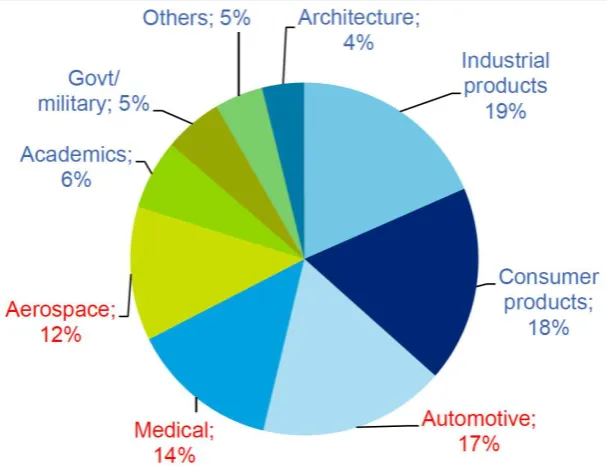
[image:29.595.157.461.400.633.2]encouraged the technology to be employed in applications and industries as end product. This is acknowledge by giant manufacturer, Boeing in which uses Stratasys's 3D printers to make some components, and is constantly working on more ways to use the technology (Cotteleer, 2014). The airline company has even built an entire cabin using one of Stratasys's 3D printers. As a result of higher demands, Boeing has produced more than 20,000 3D-printed parts. It used those pieces in 10 different types of military and commercial airplanes, like the luxurious Dreamliner. The Dreamliner has about 30 3D-printed parts. Indeed, 3D printers helps to reduce the time between the design and manufacturing stages. It also a much more cost-efficient process. Figure 2.3 shows the application of AM systems in various sectors.
As can be seen from Figure 2.3, major sectors are dominant by automotive, medical and aerospace which yields about 17 %, 14 % and 12 % respectively and
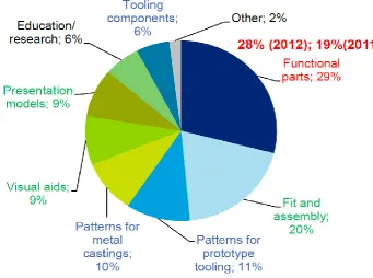
[image:30.595.148.490.327.581.2]currently leading about 43 % whereas this indicated the impact of AM systems in the industries. Therefore, regarding the AM potential in the industries, the usage will be increased significantly as a matter of time. Besides that, according to Cotteleer (2014), there is significant interest in AM systems distribution by applications whereas 29 % for functional parts, 20 % focusing on fit and assembly, 11 % for prototype tooling, 10 % for metal casting, 9 % for visual aids and models presentation and lastly 6 % goes to education research and tooling components. Recently, more companies typically spend extra time on production compare to prototyping. Figure 2.4 shows the AM systems deployment by applications in 2013.
2.3.3 Personal Desktop 3D Printer
Over the past six years, innovation in technology of AM relatively produces a new category of (AM) systems which is personal desktop 3D printers. Wohlers
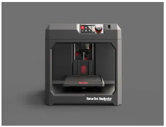
[image:31.595.158.490.273.527.2]Associates defines personal desktop 3D printers as AM systems that sell under $5,000. The category includes RepRap and RepRap derivatives, MakerBot Industries, Delta Micro Factory Corp, Cube from 3D Systems and many others. Figure 2.5 shows the personal 3D Printer that available in the market.
Figure 2.5: Personal 3D printer by Makerbot industries
study, it briefly discuss the potential of portable or personal 3D Printer to be employed in metal casting end product. The market growth reports regarding the
[image:32.595.166.491.156.350.2]personal 3D printer from 2007 until 2012 are summarized in Figure 2.6.
Figure 2.6: Market growth of personal 3D printer (Wohlers, 2013)
Generally, prototyping are important in application of 3D printing as research and development (R&D) project and part of product improvement. According to Cotteleer, (2014) most of the revenue generated by the 3D printing sector come from commercial users, as printer makers experience continued price pressure and 3D printers become more affordable. In the past, few giant companies such as 3M and Ford had participated in 3D printers and explore new product lifecycles or commercial models concept. For instances such as 3M company which has used AM to conduct research on health problems while Ford has used it to build prototype and components of the car. Regarding the 3D printer affordable prices, smaller
companies are progressively joining in the exploration of applications. Some are even purchasing 3D printers to explore new business opportunities and productivities.
promising markets for the years to come. Indeed, the commodity prices are decreasing, resulting of much cheaper prices for 3D printers, which allow a
[image:33.595.116.521.256.449.2]significantly higher demand. On the other hand, the evolution of the technology is giving the opportunity to produce at a much faster pace a much bigger amount of products. Canalys, (2014) predicts the global 3D printing market will grow from $2.5B in 2013 to $16.2B by 2018, attaining a growth average of 45.7% in the forecast period. Figure 2.7 shows the comparison of forecasts and relative market growth by 3D printers, services and materials.
Figure 2.7: Global 3D printing market estimates and forecast (Canalys, 2014)
Nevertheless, when matching between personal 3D printers with high end 3D printers that commonly used in the industrial, there are difference between both systems. Firstly is regarding its cost, whereby personal desktop 3D printer is cheaper rather than high end 3D printer. Thus, personal desktop 3D printer has less capability due to the inexpensive and compactible size. The printer is capable on printing the small 3D objects, usually up to the size of A5. However, a new invention model has
a large scale of platform measuring up to 210mm (X) x 210mm (Y) x 240mm (Z). Besides that, other important different is regarding its printing quality resolution.
improving the quality of low end 3D printer. Days by days, improvement has affected the consumption of personal desktop 3D printer to be engaged in industrial
applications as a matter of fact that, it is economical in terms of cost.
2.4 Fused Filament Fabrication Technique
Nowadays, rapid growth on AM technology has spread simultaneously over the world, hence providing personal, compact and affordable desktop 3D printer for consumer usage. Commonly called by the name of Fused Deposition Modeling (FDM) in which a trademark by Stratasys. Besides that, it also may be called as Fused Filament Fabrication (FFF) or extrusion based system. Extrusion based desktop 3D printers are getting widely popular due to increasing visibility of the printers, but still industrial usage is dominant. The early industrial FDM machines are made by giant professional companies which are Stratasys and 3D Systems. Frequently, there are varieties of desktop 3D printer in market which made either by small or huge company.
As a matter of fact that most of the available desktop 3D printer process at the present time are based on the extrusion filament process in which inheritance by high end FDM machines. This process is most common and recognizable in the 3D printer process. The most common materials for entry level FFF are Acrylonitrile butadiene styrene (ABS) and Polylactic acid (PLA). Besides that, other materials also are available such as flex and conductive ABS in which comes with variety of colours.
only one nozzle working, it is challenging to provide efficiency supports. Thus, as the system has advanced to integrate dual extrusion head nozzle, the issue become
[image:35.595.190.444.207.478.2]less important. With the improvement in dual extrusion, a combination of colours can be made significantly thus providing a colourful end product. Figure 2.8 shows the schematic flows of FFF process for 3D printer.
Figure 2.8: Schematic of Fused Filament Fabrication (3D PRINTING, 2014)
2.4.1 Material Characteristic for Fused Filament Fabrication Process
Generally, most common filament materials that used in FFF process are ABS and
PLA. However, this literature of material for FFF process covered the ABS material
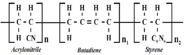
only. ABS polymer is synthesized from three combination of monomers linkage such
as acrylonitrile, butadiene and styrene. The basic molecules on ABS material are
based on carbon, hydrogen and nitrogen. The compositions of ABS have an average
composition of 27% acrylonitrile, 25% butadiene and 63% styrene (Shahir, 2010). In
resistance, while monomer butadiene provides impact strength and robustness and
lastly the monomer styrene delivers equilibrium of clearness, stiffness, easily
[image:36.595.159.480.230.325.2]processing (Shahir, 2010). The combinations of these three components provide the good characteristics and the properties of the plastics. Those properties are controlled by molecular structures as well as monomers. Figure 2.9 shows the chemical bonding linkage of ABS structure.
Figure 2.9: Chemical structure of ABS polymer (Wilks, 2001)
Figure 2.10: ABS P400 filament (3D PRINTING, 2014)
2.4.2 Properties of ABS Material
Essentially, ABS is widely used in components of plastics due to the fact that ABS has high chemical resistance, flexibility and stiffness thermoplastic polymer. In addition, ABS is exceptional choice for conceptual design prototype. Over the years, ABS has been embedded in AM process due to its precision, strength and repeatability properties. ABS is classified as thermoplastic materials that capable to fabricate complexity as well as thin layer of 3D objects. Today, there are lots of manufactures that produce ABS filament. Kindly, most of the ABS materials filament produce have different thermal and mechanical properties. This is due to the percentages of composition to be added into the filament. In addition, this is the “recipe” that most of the manufactures kept it as secret. Thus, not much company
Table 2.2: Thermal and Mechanical properties of ABS P400 (Stratasys, 2011)
Thermal and Mechanical Properties Value
Tensile Strength 22 MPa
Tensile Modulus 1627 MPa
Flexural Strength 41 MPa
Flexural Modulus 1834 MPa
Glass Transition Temperature, Tg 104°c
Coefficient of Thermal Expansion, CTE 10.08 x 10⁻⁵
2.5 Jetting Technique
This technique may be called as Polyjet, Thermojet and Muljet Modeling (MJM). Evolution in AM technology has emerged giant company to explore new process to adapt in desktop 3D printer. Hence, collaboration of two giant companies such as Objet and Stratasys has formed a new company consisting of market value worth $3 billion whereby the pattern of desktop 3D Polyjet system is taken by Stratasys. Today, there are variabilities of Polyjet desktop 3D printer based on Polyjet technology such as Object 24, Object 30, Object 30 Pro and Object 30 Prime.
The Polyjet desktop 3D printer is based on PolyJet technology system. In contrast, the indirect 3D printer processes is different concept whereby, jetting the binder into a bed of building material. Therefore there is absent of powder bed in the Polyjet desktop 3D printer process. Besides that, the Polyjet systems are differs from Stereolithography (SLA) systems whereas the materials come in the form of cartridge (no vat of liquid photopolymer).
In this case, the concept is similar to ink jet document printing whereas it has capability to print diagram onto paper. However, instead of jetting the drops of ink on paper, Polyjet desktop 3D printer jet layers of liquid photopolymer onto a build
REFERENCES
3D PRINTING. (2014). 3D Printers - How Do They Work ? What is Fused Filament Fabrication ( FFF ).
ASTM. (2012). Classification of AM process, ASTM 2012.pdf. US: ASTM.
ASTM International. (2013). ASTM International Technical Committee F42 on Additive Manufacturing Technologies, 19428.
Barclift, M. W., & Williams, C. B. (2012). Examining Variability in the Mechanical Properties of Parts Manufactured Via Polyjet Direct 3D Printing, 876–890.
Bemblage, O., & Karunakar, D. B. (2011). A Study on the Blended Wax Patterns in Investment Casting Process. Proceedings of the World Congress on Engineering 2011, 105-108.
Bird, P. (1995). Metal casting. Engineering (London), 236(9), 41–42.
Canalys. (2014). 3D printing market to grow to US$16.2 billion in 2018. Metal Powder Report, 69(3), 42.
Cheah, C. M., Chua, C. K., Lee, C. W., Feng, C., & Totong, K. (2005). Rapid prototyping and tooling techniques: A review of applications for rapid
investment casting. International Journal of Advanced Manufacturing Technology, 25(3-4), 308–320.
Chen, X., Li, D., Wu, H., Tang, Y., & Zhao, L. (2011). Analysis of ceramic shell cracking in stereolithography-based rapid casting of turbine blade. International Journal of Advanced Manufacturing Technology, 55(5-8), 447–455.
Das, a. K. (2004). Integrated Product Design Using Rapid Prototyping Technology and Rapid Tooling in Concurrent Engineering Approach. Materials Science Forum, 471-472, 672–676.
Dickens, P. M., Stangroom, R., Greul, M., Holmer, B., Hon, K. K. B., Hovtun, R.,Wimpenny, D. (1995). Conversion of RP models to investment castings.
Ding, Y., Lan, H., Hong, J., & Wu, D. (2004). An integrated manufacturing system for rapid tooling based on rapid prototyping, 20, 281–288.
Ferreira, J. C., & Mateus, A. (2003). A numerical and experimental study of fracture in RP stereolithography patterns and ceramic shells for investment casting. Journal of Materials Processing Technology, 134(1), 135–144.
Ferreira, J. C., Santos, E., Madureira, H., & Castro, J. (2006). Integration of VP/RP/RT/RE/RM for rapid product and process development. Rapid Prototyping Journal, 12(1), 18–25.
Gouldsen, C. (1998). Investment Casting Using FDM / ABS Rapid Prototype Patterns. New York, USA.
Hague, R., & Dickens, P. M. (2015). Improvements in investment casting with stereolithography patterns, 215, 1–11.
Harun, W. S. W., Safian, S., & Idris, M. H. (2009). Evaluation of ABS patterns produced from FDM for investment casting process. WIT Transactions on Engineering Sciences, 64, 319–328.
Horton, R. a. (2008). Investment Casting. Casting, ASM Handbook, vol.15, 563–621.
Jacobs, P. (1995). Rapid tooling. World Class Design to Manufacture, 2(6), 42–50.
Karunakaran, K. P., Shanmuganathan, P. V., Jadhav, S. J., Bhadauria, P., & Pandey, A. (2000). Rapid prototyping of metallic parts and moulds. Journal of Materials Processing Technology, 105(3), 371–381.
Levy, G. N., Schindel, R., & Kruth, J. P. (2003). Rapid Manufacturing and Rapid Tooling With Layer Manufacturing (Lm) Technologies, State of the Art and
Future Perspectives. CIRP Annals - Manufacturing Technology, 52(2), 589–609.
Li, H., Chandrashekhara, K., Komaragiri, S., Lekakh, S. N., & Richards, V. L. (2014). Crack prediction using nonlinear finite element analysis during pattern removal in investment casting process. Journal of Materials Processing Technology, 214(7), 1418–1426.
Marwah, O. M. F., Sharif, S., Sulaiman, S., Ibrahim, M., & Mohamad, E. J. (2014). Direct Investment Casting Numerical Study for ABS P400 FDM Materials, 660, 99–103.
Mohd, O., Marwah, F., Sharif, S., & Ibrahim, M. (2012). Direct Fabrication of IC Sacrificial Patterns via Rapid Prototyping Approaches, 6(5).
Norouzi, Y., Rahmati, S., & Hojjat, Y. (2009). A novel lattice structure for SL investment casting patterns. Rapid Prototyping Journal, 15(4), 255–263.
Omar, M. F. M., Sharif, S., Ibrahim, M., Hehsan, H., Busari, M. N. M., & Hafsa, M. N. (2012). Evaluation of Direct Rapid Prototyping Pattern for Investment Casting. Advanced Materials Research, 463-464, 226–233.
Pal, D., & Ravi, B. (2007). Rapid tooling route selection and evaluation for sand and investment casting. Virtual and Physical Prototyping, 2(4), 197–207.
Patil, R., Kumar, S. M., & Abhilash, E. (2012). Development of Complex Patterns :
Scope and Benefits of Rapid Prototyping in Foundries. International Journal of Engineering and Innovative Technology (IJEIT), 1(4), 68–72.
Polzin, C., Spath, S., & Seitz, H. (2013). Characterization and evaluation of a PMMA-based 3D printing process. Rapid Prototyping Journal, 19(1), 37–43.
Sabau, A. S. (2007). Shrinkage Prediction for the Investment Casting of Stainless Steels. Transactions of American Foundry Society, 115(07-042), 1–12.
Shahir Hashim, Azman Hassan, C. S. Y. (2010). Mechanical , Chemical and Flammability Properties of Abs / Pvc Blends Pm Dr Shahrir Hashim Pm Dr Azman Hassan Chew Sau Yen. Mehchanical, Chemical and Flammbility Porperties of ABS/PVC Blends. Universiti Teknologi Malaysia.
Sivadasan, M., & Singh, N. K. (2013). Use of fused deposition modeling process in investment precision casting – a viable rapid tooling, 1, 46–49.
Sokovic, M., & Kopac, J. (2006). RE (reverse engineering) as necessary phase by rapid product development. Journal of Materials Processing Technology, 175 (1-3), 398–403.
Stratasys. (2011). ABS P400 MECHANICAL AND THERMAL PROPERTIES. Dimension-ABS-Model-Material.
Subburaj, K., & Ravi, B. (2008). Computer aided rapid tooling process selection and manufacturability evaluation for injection mold development. Computers in Industry, 59(2-3), 262–276.
Tedds, D. F. B. (2013). The investment casting process. Institution of Production Engineers Journal, 33(12), 663.
Thymianidis, M., Achillas, C., & Tzetzis, D. (2013). Modern Additive Manufacturing Technologies : An Up- to-Date Synthesis and Impact on Supply
Chain Design. International Conference on Supply Chains.
Träxler, M., Ackermann, J., Juda, M., & Hirsch, D. (2011). Polymethyl methacrylate (PMMA). Kunststoffe International, 101(10), 42–44.
Vasconcelos, P. V., Lino, F. J., & Neto, R. J. L. (2002). The Importance of Rapid Tooling in Product Development. Key Engineering Materials, 230-232, 169– 172.
Wholers, T. (2009), “Wohlers Report 2009: State of Industry”, Wholers Associates
Inc., USA.
Wholers, T. (2013), “Wohlers Report 2013: State of Manufacturing Industry”, Wholers Associates Inc., USA.
Wholers, Terry. “Wohlers Report 2014: Additive Manufacturing and 3D Printing State of the Industry.” Wohlers Associates, Inc. 2014.
Wilks Edward S. (2001). Industrial Polymers Handbook, (102), 2396.
Wong, K. V., & Hernandez, A. (2012). A Review of Additive Manufacturing. ISRN Mechanical Engineering, 2012, 1–10.
Wong, a. C Y, and F. Lam. 2002. “Study of Selected Thermal Characteristics of
Polypropylene/polyethylene Binary Blends Using DSC and TGA.” Polymer Testing 21: 691–96
Yang, J., Shi, Y., Shen, Q., & Yan, C. (2009). Selective laser sintering of HIPS and investment casting technology. Journal of Materials Processing Technology, 209(4), 1901–1908.
Yao, W. L., & Leu, M. C. (1999). Analysis of shell cracking in investment casting with laser stereolithography patterns. Rapid Prototyping Journal, 5(1), 12–20.
Yao, W. L., & Leu, M. C. (2000). Analysis and design of internal web structure of laser stereolithography patterns for investment casting. Materials & Design, 21, 101–109.