http://dx.doi.org/10.4236/am.2015.66084
How to cite this paper: Al-Qahtani, A., Khenous, H.B. and Aly, S. (2015) Synchronization of Impulsive Real and Complex Van der Pol Oscillators. Applied Mathematics, 6, 922-932. http://dx.doi.org/10.4236/am.2015.66084
Synchronization of Impulsive Real and
Complex Van der Pol Oscillators
Ali Al-Qahtani
1, Houari B. Khenous
1, Shaban Aly
2*1Department of Mathematics, Faculty of Science, King Khalid University, Abha, KSA 2Department of Mathematics, Faculty of Science, Al-Azhar University, Assiut, Egypt Email: [email protected], *[email protected]
Received 29 August 2014; accepted 30 May 2015; published 2 June 2015
Copyright © 2015 by authors and Scientific Research Publishing Inc.
This work is licensed under the Creative Commons Attribution International License (CC BY).
http://creativecommons.org/licenses/by/4.0/
Abstract
Nonlinear systems involving impulse effects, appear as a natural description of observed evolu-tion phenomena of several real world problems, for example, many biological phenomena involv-ing thresholds, burstinvolv-ing rhythm models in medicine and biology, optimal control models in eco-nomics, population dynamics, etc., do exhibit impulsive effects. In a recent paper [1], both real and complex Van der Pol oscillators were introduced and shown to exhibit chaotic limit cycles and in
[2] an active control and chaos synchronization was introduced. In this paper, impulsive synchro-nization for the real and complex Van der Pol oscillators is systematically investigated. We derive analytical expressions for impulsive control functions and show that the dynamics of error evolu-tion is globally stable, by constructing appropriate Lyapunov funcevolu-tions. This means that, for a rel-atively large set of initial conditions, the differences between the master and slave systems vanish exponentially and synchronization is achieved. Numerical results are obtained to test the validity of the analytical expressions and illustrate the efficiency of these techniques for inducing chaos synchronization in our nonlinear oscillators.
Keywords
Real and Complex Van der Pol, Chaotic Systems, Error Systems, Impulsive Synchronization
1. Introduction
The stabilization and control of nonlinear systems is one of the most important properties of the systems and has been studied widely by many researchers in control theory (see Refs. [2]-[5]). As the key technology of secure communication, chaotic synchronization has been widely developed since Pecora and Carroll [6] proposed the
principle of chaos synchronization and realized it in the circuit in 1990. The basic behavior and chaotic synchronization have been studied by several researchers (see Refs. [7]-[10]). The concept of synchronization consists in making two chaotic systems (identical or different) which oscillate in a synchronized manner.
On the other hand, since Fowler et al. [11] introduced the complex Lorenz equations as a generalization of the real Lorenz system, many chaotic complex systems have been proposed such as chaotic complex Lu and Chen [1] [4] [8] [12], complex Van der Pol [1], and references therein.
A wide variety of methods have been proposed and applied for the synchronization of chaotic systems which include, for example, active control, global synchronization, adaptive control, linear and nonlinear feedback and back stepping design (see Refs. [5] [6] [9] [10] [13]-[15]) and references therein. The great interest in synchro-nization is not only due to the possibility of sending messages through chaotic systems for secure communica-tion, but also due to applications in other fields, such as electrical and automation engineering, biology and chemistry. The synchronized systems usually consist of two parts: A transmitter of chaotic signals (master os-cillator) and a receiver (slave osos-cillator). A chaotic signal generated by the master oscillator may be used as an input in the slave oscillator. After synchronization, the trajectory of the slave oscillator asymptotically ap-proaches that of the master oscillator and the error signal is zero.
In applied sciences and engineering there are a lot of problems involving complex variables which are de-scribed by these complex systems. For example, in secure communications, doubling the number of variables or using complex variables (which means using higher dimensional chaotic systems) increases the content and se-curity of the transmitted information and in many important fields of physics, engineering and computer science, such as laser physics, control, flow dynamics and liquid mixing, electronic circuits, secure communications and information sciences (see Refs. [11] [16]-[22]).
Recently, impulsive control has been widely used to stabilize and synchronize chaotic systems (see Refs. [23]-[27]). Its necessity and importance lie in that, in some cases, the system cannot be controlled by continuous control. For example, a government cannot change savings rates of its central bank every day. Additionally, im-pulsive control may give a more efficient method to deal with systems that cannot endure continuous distur-bance. Furthermore, impulsive method can also greatly reduce the control cost.
The main ideas of these impulses are to use samples of the state variables of the master system at discrete moments and to synchronize the slave system discretely. Once the error system of the two coupled systems is asymptotically stable, they are said to be synchronized. Generally speaking, these impulses are samples of the state variables of the master system at current discrete moments to drive the slave system. However, we can also design a novel impulse using not only current instantaneous errors, but also the previous time instants of errors. By using such a technique, we can increase the impulse distances and reduce the control cost.
In this work both real and complex Van der Pol oscillators were introduced and shown to exhibit chaotic limit cycles (see Ref. [1]). We use the impulsive control technique to achieve synchronization of both real and complex Van der Pol oscillators.
(
2)
1 0,
x+ −x −x x=
(1)
(
1)
0,z+ −z −zz z=
(2)
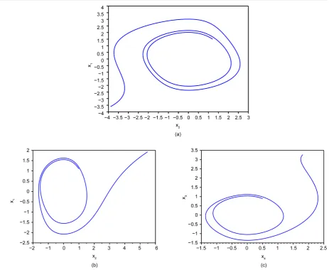
where z= +x iy is a complex function with i2 = −1, the par denotes the complex conjugate and is a scalar parameter. If we select <0 then both real and complex Van der Pol exhibit unstable limit cycles as shown in
Figure 1. These systems arise in many important applications in physics, electronics, and biology. For more details, see Refs. [1] [28]-[30]), and references therein.
The rest of the paper is organized as follows: In Section 2, a theory on the stability of impulsive nonlinear equations is given. In Section 3, we apply the impulsive synchronization technique to study the chaos synchro-nization of real Van der Pol oscillator. In Section 4, we extend this investigation to complex Van der Pol oscil-lator in a chaotic state by using the same technique of Section 3. A good agreement is found between the analyt-ical results and the numeranalyt-ical ones. Section 5 is devoted to the conclusions of this study.
2. Impulsive Control of Nonlinear System
Figure 1. (a) The phase portrait of the chaotic real Van der Pol oscillators (1) for = −0.18,x1
( )
0 =1.5,y1( )
0 =1.21, and(
)
0 0 1; 1
t = x=x x=y , and (b) x versus x, (c) y versus y the phase portrait of the chaotic complex Van der Pol oscillators
(2); for = −0.18,x1
( )
0 =1.5,y1( )
0 =1.21,x2( )
0 =1.5,y2( )
0 =1.21.economics, population dynamics see Refs. [11] [16]-[22]). The mathematical description of these impulsive systems of differential equations are usually define as an ordinary differential equations coupled with a system of difference equations, as expressed in the following system:
( )
( ) ( )
( )
0 0(
)
, ,
,
1, 2, 3, , k
k
t k k k
x f t x t t
x x t x t t t
x t x k
+ −
+
= ≠
∆ = − =
= =
(3)
where
[
0,)
, 0 0, nt∈ =J t +∞ t ≥ x∈R is the state variable, and f :J×Rn→Rn is a continuous-valued func- tion. The impulsive control law of system (3) is given by the sequence
{
t uk, k(
x t( )
k)
}
, which has the effect ofsuddenly changing the state of the system at the instants tk, where t1< <t2 < <tk , limk→∞tk = ∞ and
0 1
t <t . The difference equations are given by
( ) ( )
(
( )
)
,k
t k k k k
x x t+ x t− u x t
∆ = − = (4)
where
( )
lim( )
k
k t t
x t+ = →+ x t and
( )
lim( )
k
k t t
x t− = →− x t . For simplicity, we assume that x t
( )
k x t( )
k− =
[image:3.595.76.540.78.458.2]( )
(
)
k k
u x t can be chosen as B x tk
( )
k where Bk being n n× matrices. The objective is to find some (sufficient) conditions on the constant control gains, Bk, and the impulsive intervals(
)
1 1, 2, 3,
k tk tk k
τ = − − < ∞ = , such that the impulsively controlled system (3) is stable.
The above chaotic system can be written into the form
( )
( )
0 0(
)
,
,
1, 2, 3, , k
k
t k k
x Ax x t t
x B x t t
x t+ x k
= + Φ ≠
∆ = = = = (5)
where A is the linear part matrix of the corresponding system, and Φ
( )
x is the nonlinear part. We consider the system (5) as the master or drive system.We consider the following chaotic system described by the dynamics
( )
( )
0( ) (
0)
,
,
1, 2, 3, , k
k
t k k
y Ay y t t
y B y t t
y t+ y t k
= + Φ ≠
∆ = = = = (6)
as the slave or response system. If we define the synchronization error as
,
e= −y x (7) then the error dynamics system of the impulsive synchronization is obtained as
( )
( )
0 0(
)
, ,
,
1, 2, 3, , k
k
t k k
e Ae e t t
e B e t t
e t+ e k
= + Ψ ≠
∆ = = = = (8)
where Ψ
( )
e = Φ( )
y − Φ( )
x . We assume that the parameters of the master and slave systems are known and that the states of both systems (5) and (6) are available for measurement. Note that there exists a positive constant M for the chaotic systems (1) and (2) that x ti( )
≤M for all t. For convenience, define the following notations:( )
(
T)
(
) (
T)
2 max max
1
, .
2 k k k
A A A I B I B
λ = λ + β =λ + +
The impulsive synchronization calculations lead to the following Theorem. Theorem: If we consider the Lyapunov function defined by V x
( )
=e eT and(I) If 2λ2
( )
Ar + = <L λ 0, (λ is a constant) and there exist a constant 0≤ < −α λ, such that(
1)
lnβk−α tk−tk− ≤0,k=1, 2,. Then the trivial solution of system (8) is globally exponentially stable, that is, system (6) is globally exponentially synchronous with system (5).
(II) If 2λ2
( )
Ar + = ≥L λ 0, (λ is a constant) and there exist a constant α≥1, such that(
)
(
1)
ln αβk +λ tk−tk− ≤0,k=1, 2,. Then system (6) is globally exponentially synchronous with system (5). In the following, we will takes real and complex Van der Pol oscillators for examples to obtain some more practical results.
3. Chaos Synchronization of Two Identical Real Van der Pol Oscillators
Assume that, the system (1) has two identical chaotic Van der Pol oscillators playing the master and slave oscillators respectively. The master oscillator is described as:
(
2)
1 0,
x− −x x+ =x
(9)
and the slave oscillator is given by:
(
2)
1 0,
y− −y y+ =y
where dots denote differentiation with respect to time, x1 denotes the state vector of the master oscillator, x2
denotes the state vector of the slave oscillator.
Substituting x=x1, x1=x2 in (9) and y= y1, y1=y2 in (10) the resulting two systems of first order ODEs are:
1 2,
x =x (11)
(
2)
2 1 1 2 1,
x = −x x −x
and
1 2,
y =y (12)
(
2)
2 1 1 2 1.
y = −y y −y
We wish to obtain an appropriate impulsive synchronization such that the solution of the slave oscillator asymptotically approaches the solution of the master oscillator, hereby, the two oscillators are synchronized with each other. To do that let us consider the error equation:
1 1 1and 2 2 2
e =y −x e = y −x
According to the synchronization theory the subtraction of Equation (12) from Equation (11) now gives:
1 2,
e =e (13)
(
2 2)
2 1 2 2 1 2 1 21 1 2 .
e = − +e e − e y +x e + e x x
We can rewrite the above systems into the matrix form
(
)
1 1
2 2
2 1 2 1 1 1 2
2 2 0 0 1 . 2 1 e e
e y x e e x x
e e = + − − + +
(14)
Then the error system of the impulsive synchronization is given by
( )
( )
0 0(
)
,
,
1, 2, 3, , k
r r k
t k k
e A e e t t
e B e t t
e t+ e k
= + Ψ ≠
∆ = = = = (15)
where 0 1
1
r
A =
−
is the linear part matrix of the corresponding system,
( )
(
(
)
)
T2 2
2 1 2 1 1 1 2
0, 2
r x e y x e e x x
Ψ = − + + and tk denotes the instant when impulsive control occurs.
System (13) can be considered as a control problem, which is a function of the error vector e ii, =1, 2. Also it
is synchronized with respect to a Lyapunov function V t
( )
via the design of Impulsive control, so one can achieve synchronization between the master and the slave oscillators.Let us consider the Lyapunov function V x
( )
=e eT . For t≠τ, we have( )
( )
(
( )
)
(
( )
)
(
)
( )
(
( )
)
(
]
T T
T T 2 2 2
2 2 1 1 2 1 2 1 1
2 1 1
2 2
2 3 , , , 1, 2, 3, ,
r r
r r
r k k
V e t A e e e e A e e
e A A e e x y e e e e x y
A L V x t t t t k
λ −
= + Ψ + + Ψ
= + − + +
≤ + ∈ =
(16)
where 2
1
L = −M .
Corollary 1. Assume that tk = >τ 0 and matrices Bk =B k
(
=1, 2,)
.I) If 2λ2
( )
Ar +2L1= <λ 0 and there exists a constant 0≤ < −α λ, such that lnβ ατ− ≤0, then the system (12) is globally exponentially synchronous with system (11).( )
ln αβ +λτ ≤0,k=1, 2,, then system (12) is globally exponentially synchronous with system (11).
According to Equation (16), the fixed point of system (13) is asymptotically stable, which means that the errors e ii
(
=1, 2)
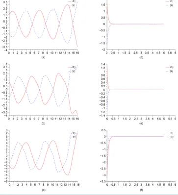
vanish as t goes to infinity.Systems (11) and (12) with (13) are solved numerically using Scilab software and the simulation results are shown in Figure 2 for = −0.18, x1
( )
0 =1.5, y1( )
0 =1.21 and x2( )
0 = −1.5, y2( )
0 = −1.21,t0 =0. The eigenvalues are 0, −0.36. Then 2λ2( )
A = =λ 0. If we choose B=diag(
b b1, 2)
=diag(
−0.85, 0.95−)
, then(
) (
)
{
2 2}
1 2
max 1 b , 1 b 0.0225
β
= + + = . In the synchronization of two real systems, the initial conditions for thedrive and response systems are chosen as
(
1.5,1.21)
T and(
−1.5, 1.21−)
T. We can get from the simulation that the approximate bounds M2 of system (15) is 3. Thus λ=2λ2( )
Ar +3L1 =4.82. Take α =1.01, thus ifln
0.7786
αβ
τ
λ
< − = , when τ =0.75 system (11) is globally asymptotically synchronous with system (12).
Impulsive Synchronization of the Complex Van der Pol Oscillators
[image:6.595.131.495.292.691.2]We study the impulsive synchronization of the complex Van der Pol oscillator. For simplifying the the problem,
Figure 2. Left figures (a) x1 versus y1, (b) x2 versus y2, (c) error e1 versus e2, impulsively synchronization of the real Van der Pol oscillator (1) cannot be stabilized with τ = 0.85; right figures (d) x1 versus y1, (e)
we assume that we have two identical complex Van der Pol oscillator and using the same technique of sub- section 2. Oscillator (2) is a system of two coupled nonlinear Van der Pol oscillators that takes the form
(
2 2)
1 0,
x+ x +y − x+ =x
(17)
(
2 2)
1 0.
y+ x +y − y+ =y
Let x=x1, x=x2, y=x3 and y=x4, then system (12) becomes:
1 2,
x =x (18)
(
2 2)
2 1 2 1 3 1 ,
x = − −x x x +y −
3 4,
x =x
(
2 2)
4 3 4 1 3 1
x = − −x x x +y −
which represent the master oscillator, so the slave oscillator is given by:
1 2,
y =y (19)
(
2 2)
2 1 2 1 3 1 ,
y = − −y y y +y −
3 4,
y =y
(
2 2)
4 3 4 1 3 1
y = − −y y y +y −
let x=
(
x x x x1, 2, 3, 4)
T and y=(
y y y y1, 2, 3, 4)
T denote the state vectors of master and slave oscillators respec- tively and T denotes the transpose. In order to apply the impulsive synchronization, we define the error evector as:
= −
e y x (20)
The subtraction of system (18) from (19) gives a function of error vector e as follows: 1 2,
e =e (21)
(
2 2)
(
2 2)
2 1 2 2 1 3 2 1 3 ,
e = − +e e −y y +y +x x +x
3 4,
e =e
(
2 2)
(
2 2)
4 3 2 4 1 3 4 1 3 .
e = − +e e −y y +y +x x +x
We can rewrite the error systems into the matrix form
(
)
(
)
(
)
(
)
1 1
2 2 2 2
2 1 3 2 1 3
2 2
3 3
2 2 2 2
4 4 4 1 3 4 1 3
0 0 1 0 0
1 0 0
.
0 0 0 1 0
0 0 1
e e
y y y x x x
e e
e e
e e y y y x x x
− − + + + = + − − + + + (22)
Then the error system of the impulsive synchronization is given by
( )
( )
0 0(
)
,
,
1, 2, 3, , k
c c k
t k k
e A e e t t
e B e t t
e t+ e k
= + Ψ ≠
∆ = = = = (23) where
0 1 0 0
1 0 0
, 0 0 0 1 0 0 1
is the linear part matrix of the corresponding system and
( )
(
)
(
)
(
)
(
)
2 2 2 2
2 1 3 2 1 3
2 2 2 2
4 1 3 4 1 3
0
. 0
c
y y y x x x
x
y y y x x x
− + + +
Ψ =
− + + +
Let us consider the Lyapunov function V x
( )
=e eT . For t≠τ, we have( )
( )
(
( )
)
(
( )
)
(
)
(
)
(
)
(
)
(
)
( )
(
( )
)
( )
(
( )
)
( )
(
( )
)
(
]
T T
T T 2 2 2 2 2 2 2 2
2 2 1 3 2 2 1 3 4 4 1 3 4 4 1 3
2
2 2 2
2 2
2 1 2 3 4 2
2 2 1
2
2 4 2 2 2 8
2 8 , , , 1, 2, 3, ,
c c c c
c c
k k
V e t A e e e e A e e
e A A e y e y y x e x x y e y y x e x x
A V x t M e e e e A M V x t
A L V x t t t t k
λ λ
λ −
= + Ψ + + Ψ
= + + − + + + − + + +
≤ − + + + ≤ −
≤ + ∈ =
(24)
where 2
2
L = −M .
Corollary 2. Assume that tk = >τ 0 and matrices Bk =B k
(
=1, 2,)
.I) If 2λ2
( )
Ac +8L2= <λ 0 and there exists a constant 0≤ < −α λ, such that lnβ ατ− ≤0, then the sys- tem (19) is globally exponentially synchronous with system (18).II) If 2λ2
( )
Ac +8L2= ≥λ 0, (λ is a constant) and there exist a constant α≥1, such that( )
ln αβ +λτ ≤0,k=1, 2,, then system (19) is globally exponentially synchronous with system (18).
If <0 then V is negative and the system (21) is asymptotically stable which mean the error ei ap- proaches zero as t approaches infinity.
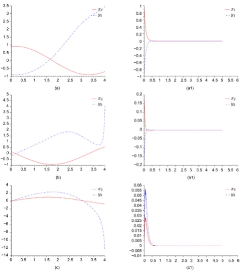
Systems (18) and (19) with (21) are solved numerically using Scilab software and the simulation results are shown in Figure 3 for = −0.18, x1
( )
0 =1.5, y1( )
0 =1.21 and x2( )
0 = −1.5, y2( )
0 = −1.21,t0 =0. The eigenvalues are 0, −0.18. Then 2λ2( )
A = =λ 0. If we choose(
1 2 3 4)
(
)
diag , , , diag 0.85, 0.95, 0.85, 0.95
B= b b b b = − − − − , then
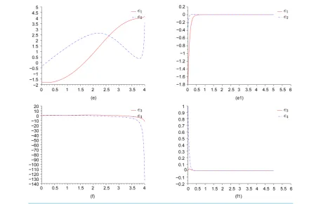
Figure 3.Left figures (a) x1 versus y1, (b) x2 versus y2, (c) x3 versus y3, impulsively synchronization of the complex Van der Pol oscillator (2) cannot be stabilized with τ = 0.85; right figures (a1) x1 versus y1, (b1) x2 versus y2, (c1) x3
[image:8.595.197.438.416.685.2]Figure 4.Synchronization errors solutions of system (21) cannot be stabilized with with τ = 0.85; (e), (f)
and can be stabilized with τ = 0.75; (e1), (f1).
(
) (
) (
) (
)
{
2 2 2 2}
1 2 3 4
max 1 b , 1 b , 1 b , 1 b 0.0225
β
= + + + + = . In the synchronization of two real systems, the initialconditions for the drive and response systems are chosen as
(
3.0, 4.0, 3.0, 4.0)
T and(
6.0, 7.0, 6.0, 7.0)
T. We can get from the simulation that the approximate bounds M2 of system (23) is 3. Thus( )
2 2
2 Ac 8L 12.96
λ= λ + = . Take α =1.01, thus if
τ
lnαβ
0.2919976573λ
< − = , when τ =0.2 system (18)
is globally asymptotically synchronous with system (19). Synchronization errors solutions of systems (21) are shown inFigure 4.
4. Conclusion
In this paper, we have applied an impulsive control technique for both real and complex Van der Pol oscillators to synchronize the chaotic limit cycles. This technique is widely used in the control of chaotic dynamical sys-tems. The simulation results illustrate that, the trajectory of the slave system of both real and complex oscillators asymptotically approaches its analog of the master system, and finally the two systems implement their mutual synchronization.
Acknowledgements
We are very grateful to to all members of Applied mathematics Group (Department of Mathematics, Faculty of science, King Khalid University, KSA) for useful discussions on the topics investigated in this paper.
References
[1] Mahmoud, G.M., Aly, S.A. and Farghaly, A.A. (2004) Chaos Control of Chaotic Limit Cycles of Real and Complex Van der Pol Oscillators. Chaos, Solitons and Fractals, 21, 915-924. http://dx.doi.org/10.1016/j.chaos.2003.12.039
[3] Mahmoud, G.M., Aly, S.A. and Al-Kashif, M.A. (2008) Dynamical Properties and Chaos Synchronization of a New Chaotic Complex Nonlinear System. Nonlinear Dynamics, 51, 171-181. http://dx.doi.org/10.1007/s11071-007-9200-y
[4] Mahmoud, G.M., Rauh, A. and Mohamed, A.A. (2001) Applying Chaos Control to a Modulated Complex Nonlinear Systems. Il Nuovo Cimento, 116B, 113-126.
[5] Liao, T.L. and Lin, S.H. (1999) Adaptive Control and Synchronization of Lorenz Systems. Journal of the Franklin In-stitute, 336, 925-937. http://dx.doi.org/10.1016/S0016-0032(99)00010-1
[6] Pecora, L. and Carroll, T. (1990) Synchronization in Chaotic Systems. Physical Review Letters, 64, 821-824.
http://dx.doi.org/10.1103/PhysRevLett.64.821
[7] Mahmoud, G.M., Al-Kashif, M.A. and Aly, S.A. (2007) Basic Properties and Chaotic Synchronization of Complex Lorenz System. International Journal of Modern Physics C, 18, 235-265.
http://dx.doi.org/10.1142/S0129183107010425
[8] Mahmoud, G.M. and Aly, S.A. (2000) Periodic Attractors of Complex Damped Nonlinear Systems. International Jour- nal of Non-Linear Mechanics, 35, 309-323. http://dx.doi.org/10.1016/S0020-7462(99)00016-5
[9] Liao, T.L. (1998) Adaptive Synchronization of Two Lorenz Systems. Chaos, Solitons and Fractals, 9, 1555-1561.
http://dx.doi.org/10.1016/S0960-0779(97)00161-6
[10] Yorke, J.A. and Yorke, E.D. (1979) The Transition to Sustained Chaotic Behavior in the Lorenz Model. Journal of Statistical Physics, 21, 263-277. http://dx.doi.org/10.1007/BF01011469
[11] Fowler, A.C., Gibbon, J.D. and McGuinnes, M.J. (1983) The Real and Complex Lorenz Equations and Their Relev-ance to Physical Systems. Physica D: Nonlinear Phenomena, 7, 126-134.
http://dx.doi.org/10.1016/0167-2789(83)90123-9
[12] Mahmoud, G.M., Bountis, T. and Mahmoud, E.E. (2007) Active Control and Global Synchronization of the Complex Chen and Lü Systems. International Journal of Bifurcation and Chaos, 17, 4295-4308.
[13] Lu, J.N., Wu, X.Q. and Li, J.H. (2002) Synchronization of a Unified System and the Application in Secure Communi-cation. Physics Letters A, 305, 365-370. http://dx.doi.org/10.1016/S0375-9601(02)01497-4
[14] Mahmoud, G.M., Rauh, A. and Mohamed, A.A. (1999) On Modulated Complex Nonlinear Dynamical Systems. Il Nu-ovo Cimento, 114B, 31-47.
[15] Ott, E., Grebogi, C. and Yorke, J.A. (1990) Controlling Chaos. Physical Review Letters, 64, 1196-1199.
http://dx.doi.org/10.1103/PhysRevLett.64.1196
[16] Ning, C.Z. and Haken, H. (1990) Detuned Lasers and the Complex Lorenz Equations-Subcritical and Supercritical Ho- pf Bifurcations. Physical Review A, 41, 3827-3837. http://dx.doi.org/10.1103/PhysRevA.41.3826
[17] Vladimirov, A.G., Toronov, V.Y. and Derbov, V.L. (1998) The Complex Lorenz Model: Geometric Structure, Homoc-linic Bifurcations and One-Dimensional Map. International Journal of Bifurcation and Chaos, 8, 723-729.
http://dx.doi.org/10.1142/S0218127498000516
[18] Jones, C.A., Weiss, N.D. and Cataeno, F. (1985) Nonlinear Dynamos: A Complex Generalization of the Lorenz Equa-tions. Physica D: Nonlinear Phenomena, 14, 161-176. http://dx.doi.org/10.1016/0167-2789(85)90176-9
[19] George, P. (1989) New Exact Solutions of the Complex Lorenz Equations. Journal of Physics A, 22, 137-141.
http://dx.doi.org/10.1088/0305-4470/22/5/001
[20] Roberts, P.H. and Glazmaier, G.A. (2000) Geodynamo Theory and Simulations. Reviews of Modern Physics, 72, 1083- 1123. http://dx.doi.org/10.1103/RevModPhys.72.1081
[21] Panchev, S. and Vitanov, N.K. (2005) On Asymptotic Properties of Some Complex Lorenz-Like Systems. Journal of Calcutta Mathematical Society, 1, 181-190.
[22] Toronov, V.Y. and Derbov, V.L. (1997) Boundedness of Attractors in the Complex Lorenz Model. Physical Review E,
3, 3689-3692. http://dx.doi.org/10.1103/PhysRevE.55.3689
[23] Lakshmikantham, V., Bainov, D. and Simeonov, P. (1989) Theory of Impulsive Differential Equations. World Scienti- fic, Singapore.
[24] Yang, T., Yang, L.-B. and Yang, C.-M. (1997) Impulsive Control of Lorenz System. Physica D: Nonlinear Phenomena,
110, 18-24. http://dx.doi.org/10.1016/S0167-2789(97)00116-4
[25] Chen, S.H., Yang, Q. and Wang, C.P. (2004) Impulsive Control and Synchronization of Unified Chaotic System. Chaos, Solitons & Fractals, 20, 751-758.
[26] Richter, H. (2001) Controlling the Lorenz System: Combining Global and Local Schemes. Chaos, Solitons and Frac-tals, 12, 2375-2380.
http://dx.doi.org/10.1016/S0960-0779(98)00056-3
[28] Stewart, I. (2000) The Lorenz Attractor Exists. Nature, 406, 948-949.
[29] Hayashi, C. (1964) Nonlinear Oscillations in Physical Systems. McGraw-Hill, New York.