© 2017, IRJET | Impact Factor value: 5.181 | ISO 9001:2008 Certified Journal | Page 1337
Computer Integrated Design, Analysis and Shape Optimization of
Proton Beam Dump
Sadia Khattak
1, Mohammed Ali
21
P.G. Scholar, Computer Integrated Manufacturing, Medi-Caps Institute of Technology & Management, Indore,
M.P., India
2
Professor, Department of Mechanical Engineering, Medi-Caps Institute of Technology & Management, Indore,
M.P., India
---***---Abstract -
This paper presents a solution to the problemsfaced in design, analysis and shape optimization of Beam Dump for high powered Proton Beams for SNS Target. The shape optimization of cooling channel ensures the thermal and structural stability for the assembly for the desired energy and intensity of the Proton Beam. SNS Target deals with high energy Proton Beams leading to the issues like induced radioactivity, neutron spalling reactions, secondary particles’ production, and embrittlement due to radiation. The energy of the beams may be as high as several megajoules. After carrying out literature reviews it has been found that most of the work is based upon the hand calculations obtained using already available correlations and then using them in the simulation modules. The best solution can be obtained by deriving results from one module and importing them as input to another module using the simulation software like ANSYS Workbench 15.0.
Key Words: Shape Optimization, Proton Beam Dump,
SNS Target, CFD Analysis, Simulation.
1.
INTRODUCTION
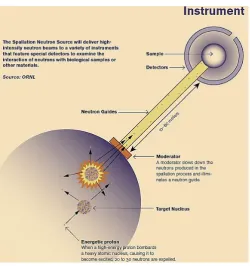
When a rapid moving particle, for example, a high-energy proton assails a nucleus of a heavy atom, some of the neutrons either gets “Spalled”, or gets jolted out from the nucleus. This phenomenon is known as Spallation. Other neutrons get heated up due to the high energy involved. Every proton that strikes the target nucleus expels around 20-30 neutrons. Waveguides Channel beams of the spalled neutrons are guided towards the instruments using the Waves. They probe the structures and properties of the materials. Spallation Neutron Source Reaction (SNS) can be better understood through Fig -1 [1].
Researchers need a bright source of neutrons for a better understanding of the material structure and motion of the molecules. The SNS provides such bright neutrons. SNS is capable of producing many pulses of neutrons that too for very minute time span as milliseconds. Hence, more than ten times more neutrons are produced. The behaviour of scattering of neutrons from a target material reveals the structure and properties. Thus, it is essential to determine the energy of the neutrons that strikes the material. In a
[image:1.595.312.545.303.439.2]pulse, as all of the neutrons depart simultaneously, the time of flight of each neutron reveals its velocity and hence its energy. Fig -2 depicts schematic diagram of SNS [2].
Fig -1: Spallation Neutron Source (SNS) reaction
[image:1.595.309.560.470.737.2]© 2017, IRJET | Impact Factor value: 5.181 | ISO 9001:2008 Certified Journal | Page 1338
The energy and intensity involved in the SNS Target may runinto several megajoules. Proton Beam Dump is employed to absorb the proton beams safely. It also offers the facility to study the beam characteristics. In order to contain the heat of such high intensity beams safely it is essential to design the Beam Dump based upon thermo-mechanical stability.
2.
LITERATURE REVIEW
High-Current Negative-Ion Source for Pulsed Spallation Neutron Sources was reported by J. R. Alonso. The author studied the significance of neutron scattering for a high-power, 1- 5 MW, accelerator-driven source (ADS) of neutrons for carrying out research upon the materials. The author has found that the accelerator if is correctly configured could induce very short, say, up to sub-microsecond, outbreaks of cold neutrons and the defined time structure offers benefits over the uninterrupted flux from a reactor. The abortion of the ANS reactor project hiked the exigency to develop an extensive strategy taking care of the best technological frameworks. The author figured out that the studies to that date had been done as per the experience obtained from the ISIS which has a 160 kW source in UK. Also, the conducted studies were based upon a high-current, up to 100 mA peak, H- source-linac combination which instilled into the accumulator rings. It was found that the beam may be further accelerated in the accumulator rings. The author proposed the extraction of 1- GeV proton beam in a single turn and bringing it to the target-moderator stations. It was concluded that the ion source requires high duty factor, high current, exceptional reliability, and great illuminations. The author observed that the community of the ion source found this a very pervasive challenge. The Workshop was conducted by the author in Berkeley in October 1994 to analyze the requirements of origin for contemplated schemas for the accelerator, the performance proficiencies of various technologies related to H- source, and recognized requisite R&D efforts to bridge the gap [3].
A study of Negative H- Sources was conducted for accelerators by Moehs et al. They studied the ion sources including surface plasma sources along with the device, magnetron; Penning and geometries for a surface converter and also the magnetic multi-pole volume sources with as well as without caesium. The author discovered that in the LEBT systems, the extraction methods of accelerator H- ion sources are exceedingly developed to utilize the magnetic and electric fields for producing DC and pulsed and/or chopped beams with a broad range of time structures. They have employed particular ion sources at the laboratories of accelerator in addition to the physics of surface as well as volume H- yield regarding source emittance. They also conducted studies upon research trends including modelling of the aperture, thermal modelling, conditioning of the surface, and diagnostics for the laser [4].
The various concepts related to the Beam Dump were reported by Hoffstaetter et al. They described the different beam stops as required for ERL. They explained how beam stops can serve their purpose effectively. The most challenging performance requirements faced by the authors were of the Primary Beam Stop. The beam current at which they worked for Primary Beam Stop was 100 mA, and the maximum energy at the beam stop was supposed to be 15 MeV which lead to the beam power of 1.5 MW. The range of 15 MeV electrons was found to be less than 8 g/cm2 in practical beam stop materials which resulted into beam deposition over a minimum depth and size of the beam spot was observed to be of minimal small size even after energy recovery. They researched about the methods to reduce the power density at the beam stop materials. The three methods that they proposed were strong defocusing of the beam, beam rastering over a larger area, and beam stop interception at a shallow angle. For tune-up stops, they worked upon 2 µA of average current at full 5 GeV beam energy with a very low-duty-factor beam. They found that since the tune-up stops are required to work for a smaller fraction of the time and are of lesser power, hence, only fairly modest shielding will be needed by ERL facility. The stops are designed to be cooled by water systems in the accelerator tunnel. They also studied various parameters involved in the absorption of beams into the beam stops [5]. Beam Dump Window for the SNS was designed and reported by Murdoch et al. The author developed the Spallation Neutron Source Accelerator Systems for the production of neutrons using a proton beam of 1 GeV, 1.44 MW upon a liquid mercury target. The author created Beam tuning dumps to be installed at the linac's end, i.e., the Linac Dump, and in the line of Ring-to-Target transport, i.e., the Extraction Dump. Thin windows are essential to segregate the accelerator vacuum from the weak vacuum upstream of the Beam Dump. Author tackled the engineering issue such as control of high local power density that has been deposited by the electrons which are stripped from H- beam sped up in the linac. The author also handled the challenge of the necessity for low-exposure obliteration and substitution of an activated window. To facilitate window’s remote obliteration and substitution, the author carried out the thermal design of the Linac dump window, the layout of a vacuum clamp and mechanism [6].
© 2017, IRJET | Impact Factor value: 5.181 | ISO 9001:2008 Certified Journal | Page 1339
monitor chamber at BIHM. The study was carried out by theauthor about the heat generated interactions between the beam and the carbon plate. The beam under the study then propagates plate’s outer edge, and after that, to the monitor chamber through the 4 rods. The author measured the temperature differences between upstream as well as downstream ends of each rod and hence measured the heat flow. Author observed that in a carbon material, using a proton's stopping power, heat flow measurements are done which drives the measurement of the beam current [7].
18 MW Beam Dump for 500 GeV Electron/Positron Beams was designed by Walz et al. The author developed an 18 MW water-based Beam Dump for electrons or positrons for an International Linear Collider (ILC). The author conducted in-depth studies upon multi-dimensional technology for the successful design of the Beam Dump. Using bunch trains of the high energy electron/positron beam, turbulent water flow's CFD analysis, re-combiners of hydrogen/oxygen, development of auxiliary equipment, handling of radioactive 7Be and 3H, remote window, conditions for catastrophic situations, radiation shielding, etc. the author carried out calculations of power deposition [8].
Beam Dump and collimation design studies for NLS were reported by Hernando and Kalinin. Authors proposed the Beam Dump to assimilate a bunch charge of 200 pC for repetition rates ranging from 1 kHz to 1 MHz. The authors worked upon a design of a solid dump having a graphite core to assimilate the beam power up to 450 kW. Authors observed that the Beam Dump design affects the building layout. It had been found that elimination of complicated water dump can be done by using a solid dump based upon the feasibility studies. It was observed that due to beam halo particles, the post linac collimation section should secure the undulators from irradiation. The authors carried out simulations of the impact of the NLS beam in various solutions of solid Beam Dump. The authors studied the consequences of the beam halo on the collimators [9].
100 MeV Proton Beam Irradiation Facility was designed for the PEFP 100 MeV LINAC by Yun et al. The author carried out the study upon general propagation shape and spatial distribution of proton beam which was to be extracted from the vacuum in the beamlines through beam window by Monte Carlo method so that proton beams can be utilized for research and development purpose. The author designed the arrangement like Beam Window, Beam Dump, Support Frame, etc. such that nonlinear proton beam transports to the target room, spread out by the octupole magnet in the target chamber so as to provide large and uniform proton beams. TRACE-3D was used for simulation for defining basic parameters of the beamlines. Based on the studies and results, beam irradiation elements as well as their configuration were designed. The irradiation equipment was designed in the target room to ensure safety from radiation, beam observation and beam current monitoring
specification. Based on the comparative study, the author chose the material such that residual radioactivity gets reduced for the Beam Dump and irradiation equipment to ensure the safety of the worker [10].
Thermal Analysis for 100 MeV Proton Beam Dump was reported by Yoon et al. The authors presented the work of construction of a 100 MeV proton linear accelerators to supply 20 MeV or 100 MeV proton beams to users for the utilization of the proton beams for the purpose of research and development. The authors explained the plan of PEFP of 10 Target rooms so as to meet the demands of the users, each of which serving a unique characteristic purpose. The authors observed that the Beam Dump being of the essential components of the beam irradiation facility in the target room preventing proton beam to interact with other elements of the target room. Hence, Beam Dump design should be such that it can withstand such high radiation and thermal damage [11].
Beam Dump for Low Flux Beamline was designed by Kim et al. The author has developed a beamline for the low flux of Proton Beam Dump which was designed to stop 100 MeV beams with the maximum power of 8 kW. Such working conditions results in the increase in temperature, therefore, the author developed the Beam Dump such that it could withstand such high-temperature along with the radioactive circumstances. The thermo-mechanical analysis was done using ANSYS code. The Design features for the Beam Dump were estimated and then for Thermal Loading conditions the author assumed Gaussian round beam with the total beam power of 8 kW. The cooling system for the Beam Dump with water as the coolant was designed considering Rectangular ducts' Turbulent Flow to provide thermo-mechanical stability. Material selection was made by taking thermal conductivity, structural strength and residual radioactivity into consideration. The author figured out the location of maximum temperature for each material using thermal analysis when the maximum load was applied so as to find the suitable material for given boundary conditions. By changing the inclination angle of the beam the author reduced beam flux of the low flux density of proton beamline [12].
© 2017, IRJET | Impact Factor value: 5.181 | ISO 9001:2008 Certified Journal | Page 1340
produced in materials were analyzed to choose a BeamDump material for low activation [13].
A preliminary design of a Beam Dump for High-Energy Proton Accelerator of PEFP was proposed by Kim et al. The authors developed the Beam Dump for the beam of power 160 kW. The proton energy and the average current of the Korean Multipurpose Accelerator for which the authors developed the facility are 100 MeV and 1.6 mA, respectively. The concept behind the design was to spread the given beam as widely as possible upon the surface area of the Beam Dump to absorb such a high intensity of the beam. The authors studied the concept of a 100 MeV PEFP Beam Dump so as to safely contain the beam striking the surface of the Beam Dump. The authors carried out analysis for a 100 MeV proton power density distribution, calculation of stopping range, neutron-photon analysis and residual activities upon six different materials so as to select the appropriate material for the Beam Dump. The six different materials considered for the study were water, graphite, nickel, iron, copper and aluminum. An erosion test and a bending test for nickel coated surface were carried out by the authors for the assessment of the structural integrity. The authors also performed preliminary heat transfer and thermal analysis. The authors conducted research, and it was then concluded that copper is relatively better material for the 100 MeV Beam Dump taking into account its residual activity and hence the designed Beam Dump is structurally safe [14].
Beam Dump Window for CSNS was designed by Nie et al. Beam Dump Window is one of the most essential components of Beam Dump of China Spallation Neutron Source (CSNS). Authors studied the structure, material, and other related issues and concerns. Thermal analyses for the Beam Dump window design was conducted by the authors. Based upon the comparative studies, the authors chose Glidcop®AL-15 and 316L as the window material. The authors have designed window section as inner convex spherical surface and had set the thickness of the window from 1.5 mm to 3 mm by structure optimization. Window safety was confirmed by the authors under the damage of magnet. By performing the analyses, the authors, hence, verified that the window could satisfy the stipulations of CSNS Beam Dump [15].
3.
DISCUSSION
A neutron source is a device that emits Neutrons. Various mechanisms produce neutrons. Neutrons sources have many applications, for engineering, research, medicine, petroleum exploration, chemistry and most importantly in nuclear power. Following are the means in which a Neutron Source can be characterized [16]:-
1. The significance of the source:
i) Large (significant) neutron sources (a) Nuclear reactors,
(b) Fusion systems, (c) Spallation sources.
ii)Medium neutron sources
(a) Bremsstrahlung from electron accelerators or photo-fission,
(b) Dense plasma focus, (c) Light ion accelerators.
iii) Small neutron sources (a) Neutron generators,
(b) Radioisotope source - (α,n) reactions, (c) Radioisotope source - (γ,n) reactions, (d) Radioisotope source – spontaneous fission. 2. Intensity: The rate of neutrons emitted by the source. 3. Energy distribution of emitted neutrons.
4. Angular distribution of emitted neutrons.
5. Mode of emission: Continuous or pulsed operation.
Neutrons are the neutral particles which travel in straight lines. Neutrons deviate from their path only when they collide with a nucleus. Upon collision with a nucleus, neutrons either scatter into a new direction or get absorbed. ‘Flight of the Neutrons’ (i.e. time taken by neutrons to reach the target) doesn’t get affected by the electrons surrounding (commonly known as ‘Atomic Electron Cloud’) and by the electric field caused by a positively charged nucleus. In short, neutrons collide with nuclei, not the atoms. Transmission of neutrons through bulk matter is characterized by the mean free path length (λ), i.e., the average distance travelled by a neutron between the two interactions. Mathematically, λ = 1/Ʃ … (1) Interaction of neutrons with the nucleus may occur in one of the following ways [2, 17-19]:-
1. Scattering Reactions i) Elastic Scattering (n,n) ii) Inelastic Scattering (n,n’)
2. Absorption Reactions i) Radioactive Capture (n,γ)
ii) Particle Emission ((n,p), (n,α), (n,t) etc) iii)Nuclear Fission (n,f)
3. Transfer Reactions
i) Charged-particles production (n,α), (n,p) ii) Neutron production reaction (n,2n), (n,3n)
4. Spallation Reaction
© 2017, IRJET | Impact Factor value: 5.181 | ISO 9001:2008 Certified Journal | Page 1341
including neutrons. Such a kind of reaction is known asSpallation Reaction. They occur for neutron energy equal or above 100 MeV.
At present, neutron sources can be classified as:-
1. Based on Fission Reactors using highly enriched U-235, 2. Accelerator-based pulsed source, where neutrons are
produced by spallation sources.
A Particle Accelerator is a machine that uses electromagnetic fields to propel charged particles to nearly light speed and to contain them in well-defined beams. The Proton Beam Dump, commonly known as Proton Beam Stop, is a device that’s designed to safely absorb the energy of photons within the Particle Accelerators, either for maintenance (non-working phase) or the purpose of the study of the beam characteristics. From the extensive literature review it has been found that the beams being absorbed have higher energy level up to several MeV and the nature of the beams may vary from continuous to pulsed form. Thus the temperature of the Beam Dump increases to a greater extent. The purpose of the Proton Beam Dump is to assimilate a beam of ‘Protons’ safely. Beam Dumps may be classified as follows:
1.1
Primary Beam Dump
Primary Beam Dumps are the kind of Beam Dumps that must dissipate up to 1.5 MW of beam power generated by the power source. Range of beam for such kind of Beam Dumps is short yet the shorter beam spot size is capable of destroying the material where the beam strikes [5].
1.2
Tune-up Beam Dump
Tune-up Beam Dumps are the kind of Beam Dumps that are put around the path of the beam. They occupy a fail-safe position out of beam path. Their active part is put within the vacuum system of the accelerator and is moved in and out of the beam through an isolated mechanism of bellows. Tune-up Beam Dumps are put when it is essential to set-Tune-up a beam following a shutdown or when it desired to check various parameters of the accelerator such as linear optics or cavity phasing. Theses Beam Dumps are capable of dissipating very high powered beams at full energy continuously. Since these Beam Dumps are used for only small fraction of time, hence, only moderate amount of shielding is required [5].
Based upon the literature study, it has been found that the beams can be safely absorbed into the Beam Dump by reducing the power density where the beams intercept the surface of the Beam Dump. The power density of the beam may be reduced by adopting one or more of the following measures:-
a) Strong defocussion of the beam, b) Rastering the beam over larger area,
c) Adopting taper for the interception of the beams, d) Using duty cycle concept.
The energy of the beams that are to be absorbed can rise up to several Megajoules, hence, coping up with the heat dissipation can be a major issue. The materials utilized for the assembly of Proton Beam Dump can vary based upon the energy and nature of the beam as well as based upon the characteristics of the beam. The materials which can be used are Copper, Graphite, Glidcop (an alloy of Copper), Nickel, Aluminum, etc. The block of the material is often provided with a long conical hole. The beam hits the block of the material at the conical end to increase the area of the affected region, i.e. by facilitating the beam spread.
Hence, Thermal Analysis of Proton Beam Dump is an important study which aids in achieving the Thermal stability for the Beam Dump. Shape optimization of the cooling channel helps in achieving better heat transfer from the Beam Dump.
It has been observed that a lot of work has been done by the thermal analysis as well as the simulation for the development of the Beam Dump. However, most of the work is based upon the hand calculations that are obtained by applying the concepts and already available correlations and then using them in the simulation modules directly. The automatic calculation of the desired values using the software is not yet reported much. The method of deriving results from one module and then importing them as the constraint for the other module hasn’t been reported much regarding the Beam Dump.
Although for initial boundary conditions theoretical results are necessary but if the entire design is relied upon them then in the actual application the Beam Dump might fail in its utility. In practical application, various factors may affect the working of the Beam Dump. Hence, simulation not only helps in reflecting the results of the real-world application of the Beam Dump but also helps in deriving the results by linking various modules together. The simulation software like ANSYS Workbench facilitates the simulation results for the Beam Dump. Using the initial constraints like time, properties of material, velocity of cooling medium and heat load, the expected heat transfer values such as convective coefficient of the cooling medium may derived from the module Fluid Flow (FLUENT) of ANSYS Workbench. When the results from Fluid Flow (FLUENT) are linked directly to another module like Steady-State/Transient Thermal and comparative studies are carried out between the results obtained in the modules, the accuracy and repeatability of the results may be verified.
4.
CONCLUSION
© 2017, IRJET | Impact Factor value: 5.181 | ISO 9001:2008 Certified Journal | Page 1342
amount of time. The gap to generate the results for thermalanalysis and simulation using theoretical calculations can be solved by deriving results from one module to another through linked analyses of the simulation software like ANSYS Workbench. Upon comparing the results obtained from the simulation for shape optimization of cooling channel considering various cross-sections, better heat-transfer can be obtained. This procedure of optimization, hence, ensures thermos-mechanical stability to the Proton Beam Dump. Thus, the Beam Dump’s functional aspect is maximized and the various cost-related issues under a set of conditions are minimized.
ACKNOWLEDGEMENT
Authors would like to express sincere gratitude to Dr. Sunil K. Somani, Director, Medi-Caps Institute of Technology & Management, Indore (M. P.), India for his continuous support and encouragement during the above study.
REFERENCES
[1] “IAEA benchmark of Spallation Models”, Nuclear Data
Services, https://www.nds.iaea.org/spallation.
[2] SNS: Neutrons for “molecular movies”,
http://www.symmetrymagazine.org/sites/default/files /legacy/pdfs/200606/sns.pdf.
[3] J. R. Alonso, “High-current negative-ion sources for
pulsed spallation neutron sources: LBNL Workshop”, Review of Scientific Instruments, vol. 67, no.3, p1308, 01 March 1996.
[4] D. P. Moehs, J. Peters and J. Sherman, “Negative
Hydrogen Ion Sources for accelerators”, IEEE, vol. 33, no. 6, pp1786-1798, December 2005.
[5] G. H. Hoffstaetter, S. M. Gruner and M. Tigner, “Beam
Stops”, 6 December 2013,
https://www.classe.cornell.edu/rsrc.Home/Research/E RL/PDDR/2.8_Beam_Stops.pdf.
[6] G. Murdoch, A. Decarlo, S. Henderson, S. Kim, K. Potter, T.
Roseberry, J. Rank and D. Raparia, “Beam dump window design for the Spallation Neutron Source”, Particle Accelerator Conference, USA, 2003.
[7] K. Satou, N. Hayashi, H. Hotchi, Y. Irie, M. Kinsho, M.
Kuramochi, P. K. Saha and Y. Yamazaki, “Development of a beam induced heat-flow monitor for the beam dump of the J-PARC RCS”, Particle Accelerator Conference-7, Albuquerque, 2007.
[8] D. Walz, J. Amann, R. Arnold, A. Seryi, P. Satyamurthy, P.
Rai, V. Tiwari, K. Kulkarni and H. Vincke, “Design of an 18 MW beam dump for 500 GeV electron/positron
beams at an ILC”, 1st International Particle Accelerator Conference, Koyoto, Japan, 2010.
[9] J. L. F. Hernando and D. A. Kalinin, “Beam dump and
collimation design studies for NLS: Thermal and structural behaviour”, 1st International Particle Accelerator Conference, Koyoto, 2010.
[10] S. P. Yun, B. S. Park, K. T. Seol, Y. G. Song, H. S. Kim, J. H.
Jang, H. J. Kwon and Y. S. Cho, “Design of 100 MeV proton beam irradiation facility for the PEFP 100 MeV LINAC”, IPAC, New Orleans, 2012.
[11] S. P. Yoon, H. S. Kim, B. S. Park, H. J. Kwon and Y. S. Cho,
“Thermal analysis for 100 MeV proton beam dump in the target room”, KNS spring meeting, Jeju, 2012.
[12] C. R. Kim, H. S. Kim, H. J. Kwon and Y. S. Cho, “Design of
the beam dump for low flux beamline in KOMAC”, 7th International Particle Accelerator Conference, Busan, 2016.
[13] C. S. Gil, D. H. Kim and J. Kim, “Activation analyses of
beam dump materials irradiated by 100 MeV protons”, Korean Physical Society, vol. 52, no. 93, pp799-804, March 2008.
[14] J. Kim, D. H. Kim, Y. Maeng and C. S. Gil, “Preliminary
design of a beam dump for the high-energy”, Journal of the Korean Physical Society, pp1396-1398, May 2007.
[15] X. J. Nie, L. Liu and H. j. Wang, “Beam dump window
design for CSNS”, Chinese Physics C, p7, 2014.
[16] “Neutron sources”,
http://www.nuclear- power.net/nuclear-power/reactor-physics/atomic-
nuclear-physics/fundamental-particles/neutron/neutron-sources/.
[17] “Interactions of neutrons with matter”,
http://www/nuclear-power.net/nuclear-
power/reactor-physics/atomic-nuclear- physics/fundamental-particles/neutron/interactions-neutrons-matter/.
[18] H. Frýbort and J. Heraltová, "Interaction of neutrons
with matter”, Neutron Interactions, Prague, 2014.
[19] F. Rösch, Nuclear- and Radiochemistry, De Gruyter