http://dx.doi.org/10.4236/jpee.2014.24010
How to cite this paper: Song, X.N. (2014) Analysis of a Methanol-Power Polygeneration System from Natural Gas. Journal
Analysis of a Methanol-Power
Polygeneration System from Natural Gas
Xiaona Song
Electrical and Mechanical Practice Center, Beijing Information Science & Technology University, Beijing, China Email: [email protected], [email protected]
Received November 2013
Abstract
This paper analyzes the characteristics of a Natural Gas (NG)-based Methanol-Power Polygenera-tion System (MPPS). The structures and parameters of the polygeneraPolygenera-tion systems are investi-gated to explore the appropriate process for each polygeneration system. And some effective me-thods, such as exergy distribution analysis and energy-utilization diagrams (EUD) are adopted to investigate the performance & characteristic of the system. The results reveal that, MPPS adopted Partial Reforming and Partial Cycling synthesis (PR/PC) process can reach good performance, while MPPS exhibits poor performance when adopting Full Reforming and Once Through synthe-sis (FR/OT) process. Through further study with exergy analysynthe-sis method, we find that the particu-lar synthesis and separation properties of methanol lead to such difference. Therefore, the cha-racteristics of chemical product should be important factors in the configuration and integration of polygeneration systems. The work of this paper is significant for the research and development of polygeneration system.
Keywords
Polygeneration System; Exergy Distribution Analysis; EUD
1. Introduction
How to enhance the efficiency is an eternal topic for energy utilization system. To achieve this target, most ef-forts are focused on elevating the performance of components and system integration. For system integration, the idea of integrating of the chemical process and power production process, also known as polygeneration system, is rising and attracting more and more attentions [1-7].
Generally, most of studies on polygeneration system are focused on system innovation, performance study, exergy analysis, or techno-economic analysis. For example, Gao L. et al. analyzed coal-based polygeneration system by means of exergy method [2]. Li H., et al. proposed a new natural gas-based polygeneration system for power and methanol production [3]. Michiel J.A. et al. discussed the possibilities of biomass-based polygenera-tion system [4]. Chiesa P. et al. proposed a series of hydrogen-electricity polygeneration systems with CO2
im-portant factor for design and optimization of polygeneration systems.
The aims of this paper are: 1) to study the characteristics of different NG-based polygeneration systems; 2) to discuss the impacts on system characteristics brought by different chemical products; 3) to explore the appropri-ate process and parameters for different polygeneration systems.
2. Configuration of Natural Gas Based Polygeneration System
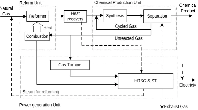
Sequential process is a high performance structure of polygeneration system. As shown in Figure 1, sequential NG-based polygeneration system consists of reform, synthesis, separation, heat recovery and power generation units. In this kind of system, all of natural gas is fed into the reform unit, in which a certain amount of natural gas is converted to CO and H2 (syngas). After being cooled in heat recovery unit, syngas enters into the
synthe-sis unit. By using different catalysts, various chemical products, such as methanol and DME, can be synthesized here. Then the raw product enters into separation unit, in which the chemical product will be separated out. The remaining, i.e. unreacted gas, can be sent to reform unit and power generation system as fuel, as well as be cycled back to the entrance of synthesis unit. The power generation unit, which is located after the separation unit, consumes a part of unreacted gas and provides the steam and work for other units or for outside.
The sequential polygeneration system is a general term of a group of systems which have the same feature of the sequential configuration of chemical process and power generation unit. Besides this common feature, dif-ferent sequential polygeneration systems may be various in structure and parameters. Here are two difdif-ferent processes which all belong to the sequential NG-based polygeneration system.
1) Full Reforming and Once Through synthesis process (FR/OT). This kind of polygeneration process adopts the full reforming scheme and the once through synthesis scheme. That is, in reform unit, nearly all of the natu-ral gas is converted to syngas. While in synthesis unit, the syngas will go through only once, all of the unreacted gas will be sent to reform unit and power generation unit as fuel, namely, the cycled gas will be canceled. This process can be shown in Figure 1 without the cycled gas.
2) Partial Reforming and Partial Cycling synthesis process (PR/PC). This kind of polygeneration process adopts the partial reforming scheme and the partial cycling synthesis scheme. That is, instead of being totally reformed, the natural gas entering into the reformer will be partially converted to syngas through lowering the reforming temperature and the ratio of steam to NG. Besides, only part of unreacted gas will be fed to reform unit and power generation unit as fuel, the remaining will be cycled. This process can be shown in Figure 1 with the cycled gas reserved.
3. Analysis of NG-Based Methanol-Power Polygeneration System (MPPS)
3.1. Evaluation Criteria of Polygeneration SystemEnergy Saving Ratio (ESR) is adopted to evaluate the performance of the polygeneration system, which is iden-tified as follows:
Separation
Unreacted Gas Natural
Gas
Heat
Reform Unit Chemical Production Unit
HRSG & ST
Exhaust Gas Steam for reforming
Gas Turbine
Power generation Unit
Chemical Product Synthesis
Heat recovery Reformer
Combustion
[image:2.595.153.474.527.705.2]Electriciy Cycled Gas
(
/)
/W e M F
ESR
W e M
η η + ⋅ − =
+ ⋅ (1)
where F is the total fuel consumption of polygeneration system; W and M denote the work output and the mass of chemical product respectively; η is the thermal efficiency of individual power generation system; e is the energy consumption for per chemical product of individual chemical production process. Thus, ESR represents the energy saved of polygeneration system compared with the individual systems when they produce the same outputs.
3.2. Performance Analysis of MPPS
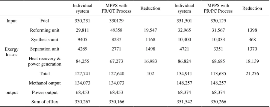
Methanol is an important product of natural gas, it is also a common chemical product of NG-based polygenera-tion system [2,3,8]. In this paper, the FR/OT and PR/PC processes of methanol-power polygenerapolygenera-tion system (MPPS) are simulated and analyzed. The main parameters and performance indexes of the two processes are shown in Table 1. Exergy analysis results are shown in Table 2. For the two tables, the comparison is based on that the polygeneration system and the corresponding individual system have the same outputs.
[image:3.595.89.544.332.515.2]We can see from Table 1 that the differences between two processes are significant. For example, the ESR of FR/OT process is only 0.03%; while for PR/PC process, the ESR can reach 6.05%. Exergy analysis results ( Ta-ble 2) reveals that, compared with individual system, the performance improvement of PR/PC polygeneration
Table 1. Performance comparison of NG-based MPPS.
Individual systems FR/OT Process
Individual systems PR/PC process chemical power chemical power
Fuel Energy Consumption (LHV, kW) 193832.6 122394.9 316120.9 214450.1 122009.8 316120.9
Reforming ratio 93.82% 93.82% 93.82% 59.14%
cycling ratio 5.35 0 5.35 4.94
Conversion ratio of syngas to methanol 96.07% 50.42% 96.07% 89.75%
Net work output W (kW) 68512.6 68512.6 68297.1 68297.1
Methanol production M (kg/hr) 21577.3 21577.3 23872.5 23872.5
Thermal efficiency η (LHV, %) 55.98% 55.98%
Energy consumption for per chemical
product e (LHV, GJ/t) 32.34 32.34
ESR (%) 0.03% 6.05%
Table 2. Comparison of exergy distributions in NG-based MPPS (Unit: kW). Individual
system
MPPS with
FR/OT Process Reduction
Individual system
MPPS with
PR/PC Process Reduction
Input Fuel 330,231 330129 351,501 330,129
Exergy losses
Reforming unit 29,811 49358 19,547 32,965 31,567 1398
Synthesis unit 9405 8237 1168 10,400 10,033 368
Separation unit 4269 2771 1498 4721 3351 1370
Heat recovery &
power generation 84,255 67,273 16,983 86,824 68,685 18,139
Total 127,741 127,640 102 134,911 113,635 21,276
output
Methanol output 134,073 134,073 148,257 148,257
Power output 68,453 68,453 68,374 68,374
[image:3.595.89.540.543.721.2]system due to the reduction of exergy loss of various units, especially the Heat recovery & power generation unit. Such reduction of exergy loss actually comes from that polygeneration system can better utilize energy through integrating of the chemical process and power plant. For FR/OT process, though other units can also achieve the remarkable reduction of exergy loss, the exergy loss of reforming unit increases greatly than that of individual system, which consequently leading to low ESR.
3.3. Graphical Exergy Analysis of Reforming Process
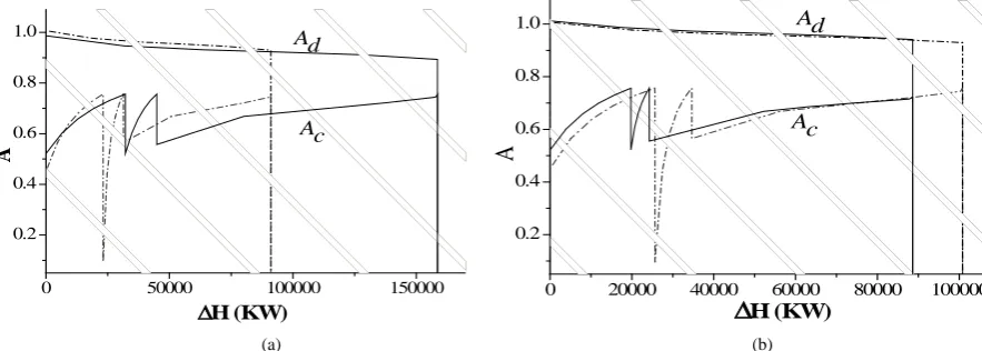
To further study the reforming unit, a graphical exergy analysis methodology, which is called energy-utilization diagrams (EUD), is adopted. In EUD diagrams, abscissa ΔH represents the enthalpy transformation quantity. And the ordinate A represents energy level. The area enclosed by energy discharging curve Ad and receiving
curve Ac represents the quantity of exergy loss in the process. Thus, in a graphical way, we can reveal the
[image:4.595.89.531.544.702.2]es-sence of energy utilization in key process and provide reference for improvement [9,10].
Figure 2 shows the EUD diagrams of reforming unit of MPPS, in which the dotted lines represent the EUD diagram of reforming unit of corresponding individual systems. For FR/OT process, we can see from Figure 2(a)
that it is the increasement of ΔH, which represents energy consumption of reforming reaction, that lead to great growth of exergy loss in reforming unit of polygeneration system. As the conversion ratio of syngas to methanol is very low in FR/OT process, to ensure same methanol output, polygeneration system need to generate more syngas than the corresponding individual system, which cause great increasement in energy consumption and exergy loss in reforming unit.
However, for PR/PC process, the higher conversion ratio of syngas to methanol makes the needed syngas de-crease. Consequently, the energy consumption and exergy loss of reforming unit are reduced. Furthermore, the condition required by reforming reaction in this process is lowered, which reduces the energy consumption and exergy loss further.
Therefore, for MPPS, the main reason for the low ESR of FR/OT process is that the conversion ratio of syn-gas to methanol is too low (Table 1). And the low one-through conversion rate is the inherent characteristics of methanol synthesis. While for PR/PC process, because the condition of reforming reaction is lowered and the cycling ratio rises (Table 1), exergy loss of reforming unit are reduced greatly, and the conversion ratio of syn-gas to methanol can significantly increase (Table 2), which ensure the good performance of the PR/PC process.
4. Conclusions
This paper studies the characteristics of NG-based Methanol–Power Polygeneration System, and also explores the appropriate process and parameters for Methanol–Power polygeneration systems.
The results indicated that: 1) Different chemical products have distinct impact on performance of NG-based polygeneration system. 2) For Methanol–Power Polygeneration System (MPPS), the PR/PC process with high cycle ratio is more suitable. 3) The reason for above phenomenon lies in the internal property of methanol syn-thesis and separation process.
0 50000 100000 150000
0.2 0.4 0.6 0.8 1.0
A Ac
Ad
∆H (KW)
0 20000 40000 60000 80000 100000 0.2
0.4 0.6 0.8 1.0
A
Ad
Ac
∆H (KW)
(a) (b)
Acknowledgements
This study has been supported by the Beijing College Youth Fellowship Program, 2013.
References
[1] Jackson, R.G. (1989) Polygeneration System for Power and Methanol Based on Coal Gasification. Coal Conversion, 3, 60-64.
[2] Gao, L., Jin, H., Liu, Z., et al. (2004) Exergy Analysis of Coal-Based Polygeneration System for Power and Chemical Production. Energy, 29, 2359-2371. http://dx.doi.org/10.1016/j.energy.2004.03.046
[3] Li, H., Gao, L., Chen, B., et al. (2006) Proposal of a Natural-Gas Based Polygeneration System for Power and Metha-nol Production. Proceedings of ECOS, Crete, 679-686.
[4] Michiel, J.A., Andre, P.C., Carlo, N., et al. (2002) Exploration of the Possibilities for Production of Fischer Tropsch Liquids and Power via Biomass Gasfication. Biomass & Bioenergy, 23, 129-152.
http://dx.doi.org/10.1016/S0961-9534(02)00037-5
[5] Chiesa, P., Consonni, S., Kreutz, T., et al. (2005) Co-Production of Hydrogen, Electricity, and CO2 from Coal with Commercially Ready Technology. Part A: Performance and Emissions. Hydrogen Energy, 30, 747-767.
http://dx.doi.org/10.1016/j.ijhydene.2004.08.002
[6] Kreutz, T., Williams, R., Consonni, S. and Chiesa, P. (2005) Co-Production of Hydrogen, Electricity, and CO2 from Coal with Commercially Ready Technology. Part B: Economic Analysis. Hydrogen Energy, 30, 769-784.
http://dx.doi.org/10.1016/j.ijhydene.2004.08.001
[7] Jin, H., Han, W. and Gao, L. (2007) Multi-Functional Energy System (MES) with Multi Fossil Fuels and Multi Prod-ucts. Journal of Engineering for Gas Turbines and Power, 129, 331-337. http://dx.doi.org/10.1115/1.2432895
[8] Steinberg, M. (1998) Production of Hydrogen and Methanol from Natural Gas with Reduced CO2 Emission.
Interna-tional Journal of Hydrogen Energy, 23, 419-425. http://dx.doi.org/10.1016/S0360-3199(97)00092-X
[9] Jin, H., Ishida, M., Kobayashi, M., et al. (1997) Energy Evaluation of Two Current Advanced Power Plants: Supercrit-ical Steam Turbine and Combined Cycle. Journal of Energy Resources Technology, 119, 250-256.
http://dx.doi.org/10.1115/1.2794998
[10] Jin, H. and Ishida, M. (1993) Graphical Energy Analysis of Complex Cycles. Energy, 18, 615-625.