6
II
February 2018
Analysis of Ten-Concentric Circular Ring Antenna
Array for Radar and Wireless Applications
K. N. Ketavath1 1
Department of ECE, K L University, Veddeswaram, Guntur, A.P
Abstract: The analysis has carried out with ten-concentric circular ring arrays to produce low sidelobes and more directivity. Using the linear array concept the sidelobe level is decreased upto -37.32 dB and increase the directivity is 73.08 dB. This proposed design is used for communications and radar systems applications.
Keywords: Concentric circular ring arrays, sidelobes, directivity, radiation patterns
I.INTRODUCTION
Concentric ring arrays (CRA) antennas used for direction finding. Ring arrays are produced directional patterns and it scan 360 degrees [1]. Streans and Stewart [2], proposes low sidelobes with concentric ring antennas. Ruban Das [3] has considered 10 ring arrays of concentric ring array to produce the sidelobe level are lower than -20 dB over the region. A circular aperture antenna are presented by Goto et al. [4] to produce radiation pattern.
Huebner [5] has presented small concentric ring arrays to produce desired pattern with maximum directivity and low sidelobe levels. Thinned array are presented by Hussain et al. [6] for phase only nulling. Some of the researchers are proposed their technique to control the sodelobe levels in [7]-[11]. Ng et al. [12] presented linear arrays for minimize sidelobe levels and control the null. concentric ring array synthesis is reported in [13] with linear arrays for wireless applications.
In view of the above studies, the analysis has carried out on ten-concentric circular ring array. These arrays are produce low sidelobes, more directivity and generate the pencil beam. Using the linear array concept the sidelobe level is decreased upto -37.32 dB and increase the directivity is 73.08 dB.
II.GENERALANALYSIS
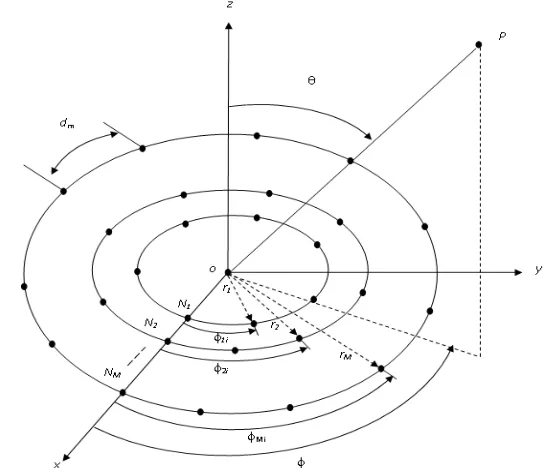
[image:2.612.170.444.481.715.2]The concentric rings antenna is placed on circular arrays, with number of elements (Nm) and radius (rm). Figure (1) presents the geometry of concentric ring arrays (CRA). The dm is ring distance between elements, m any two elements is constant, where m= 1, 2, . . . , M.
A. Proposed method
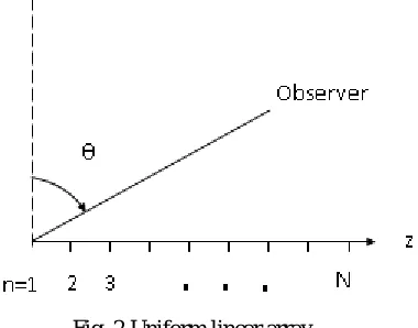
[image:3.612.219.409.145.294.2]A single radiating element is considered ten-concentric ring array. The arrangement of such elements in a linear fashion constitutes a linear ten-concentric ring array. The radiation patterns of linear concentric ring array is product of ten-concentric ring array patterns with uniform linear array patterns. Linear array shows in Figure. 2 along z-axis. Here, considered radiating element is isotropic radiator.
Fig. 2 Uniform linear array
The far-field radiation characteristics of linear ring array obtained from uniform linear array, considered the ring array elements are placed on the uniform linear array.
The radiation pattern of CRA at far-field is given by [4,13]
M 1 m mi mi m N 1 i mi1 f , 1 A expjkr sin cos( ) j
E
m
(1)
Here,
,
1f isotropic pattern,
Ami = ith element of the mth ring current excitation,
k= wave number,
azimuth angle,
m mi N ) 1 i ( 2
, elevation angle,
mi Additional phase element i of the mth ring, mi
= element i of the mth ring angular location, where, i=1,2,…,m; m=1,2,…,M
The isotropic concentric ring array far-field pattern is
M 1 m m 0 m mic 1 A N J (kr sin )
E
E (2)
The isotropic radiators uniform array radiation patterns is given by [2]
N 1 n n n n2 x sin j x
L 2 j exp ) x ( A
E (3)
Here,
A(xn)= excitation function of amplitude,
N= No. of elements on the linear array,
L 2
= Array length,
xn = Phase excitation function,
n
The radiation pattern of linear ring array of isotropic elements is obtained from the product of pattern of the ring array and patterns of uniform array. The resultant radiation pattern for linear isotropic ring array is given [13] by
N 1 n n n n M 1 m m 0 m mi c x j sin x L 2 j exp ) x ( A ) sin r k ( J N A 1 E (4)B. Directivity of linear concentric ring array
The linear isotropic CRA directivity is by[1].
2 0 0 2 c 2 s s c d d sin , E , E 4D (5)
The linear CRA with isotropic radiator using expression (7) directivity is computed numarically. The directivity of concentric ring array with isotropic radiator is computed using expression (2).
III.RESULTSANDDISCUSSIONS
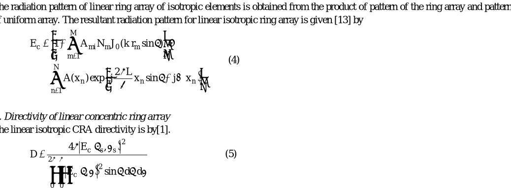
Using the equations (1) and (4), the radiation patterns of CRA and linear CRA with ten-rings are numerically evaluated using isotropic radiators. The resultant radiation patterns of the CRA and linear CRA of isotropic radiators with ten-rings are presented in figures (3–8). Using the equation (5) directivity of each pattern is evaluated.
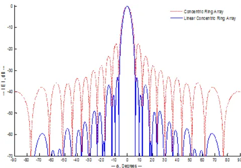
From the figure (3), a ten-concentric rings (M=10) are considered, and found sidelobe level (SLL) -17.6dB, null to null beamwidth is13.34 degrees for a single ten-concentric ring array of isotropic radiator. A ten-concentric ring array is considered as a single radiating element, such two elements (N=2) are placed on uniform linear array and found that the SLL is -17.86dB, null-to-null beamwidth is 13.34 degrees. The patterns of single element (ten-CRA, M=10) and linear ten-CRA with 2 elements (N=2) are compared. Similarly, single ten-CRA (M=10) is compared to linear CRA with N=4, 6, 9, 12, and 13 elements, these patterns are also shown in figures (4-8).
[image:4.612.48.567.76.267.2]The comparative data of null-to-null beamwidth, first SLL, second SLL, and directivity of each pattern is evaluated and tabulated in table 1.
Fig. 4 Patterns of a CRA for M=10 and N=4
Fig. 5 Patterns of a CRA for M=10 and N=6
[image:5.612.187.417.520.702.2]Fig. 7 Patterns of a CRA for M=10 and N=12
Fig. 8 Patterns of a CRA for M=10 and N=13
TABLE 1
RADIATION PATTERN OF LINEAR ARRAY ISOTROPIC CRA WITH M=10
No. of elements on
linear (N) First SLL in dB Second SLL in dB
Null-to-null beamwidth in
degrees
Directivity in dB
1 -17.60 -23.43 13.34 50.78
2 -17.86 -24.14 13.34 56.81
4 -18.92 -27.24 13.34 62.83
6 -20.81 -33.84 13.34 66.33
9 -25.41 -39.82 13.34 69.88
12 -33.32 -41.72 13.34 72.36
[image:6.612.77.535.528.717.2]IV.CONCLUSIONS
It is evident from figures (3 – 8), that the sidelobes of linear ten-CRA of isotropic radiators are less than to that of the ten-CRA of isotropic radiators. The sidelobe level is same and null-to-null beamwidth is decreased with increasing the number of concentric ring (M). Hence, the pencil beams are generated. Using the proposed method the sidelobes are decreased and beamwidth is reduced and the directivity is highly enhanced. The patterns and directivity characteristics of linear ten-CRA of isotropic radiators are very much evident from the results presented in tables 1. Thus, the proposed method is useful in radars and wireless applications.
REFERENCES
[1] G.S.N. Raju, “Antennas and Wave Propagation,” Pearson Education (Singapore) Pte., Ltd., New Delhi, 2005.
[2] C.O. Streans and A.C. Stewart, “An investigation of concentric ring arrays with low sidelobes”, IEEE Transactions on Antennas and Propagation, Vol. AP-13, pp. 856-863, November, 1965.
[3] Ruban Das, “Concentric ring arrays”, IEEE Transactions on Antennas and Propagation, pp. 398-400, May 1966.
[4] N. Goto and D.K. Cheng “On the synthesis of Concentric Ring Arrays”, Proceeding of the IEEE Transactions on Antennas and Propagation, Vol.58, pp. 839-840, May 1970.
[5] M.D.A. Huebner, “Design and optimization of small concentric ring arrays,” Proceeding of the IEEE Transactions on Antennas and Propagation, pp. 455–458, May 1978.
[6] Hussain et al., “Clutter suppression for thinned array with phase only nulling”, United States Patent, No. 5515060, May 1996.
[7] Lawrence S. Biller and Gerald E. Friedman, “Optimization of radiation patterns for an array of concentric ring sources”, IEEE Transactions on Audio and Electrostatics, Vol. AU-21, No. 1, pp.57-61, February 1973.
[8] B. Preetham kumar and G. R Branner, “Design of low sidelobe circular ring arrays by element radius optimization,” Proceeding of the IEEE Transactions on Antennas and Propagation society symposium, pp. 2032-2035, 1999.
[9] M. Dessouky, H. Sharshar, Y. Albagory, “Effecient sidelobe reduction technique for small-sized concentric circular arrays,” Progress in Elecrtomagnetics Research, PIER 65, pp. 187-200, 2006.
[10] Yasser Attia Albagory, Moawad Dessouky, Hamdy Sharshar, “An approach for low sidelobe beamforming in uniform concentric circular arrays,” Wireless PERS Communication, Vol. 43, pp. 1363–1368, December 2007.
[11] Randy L. Hupt “Thinned concentric ring arrays,” IEEE Transactions on Antennas and Propagation, pp. 1-4, 2008.
[12] B.P. Ng, M.H. Er, and C. Kot, “Linear array geometry synthesis with minimum sidelobe levels and null control,” IEE Proceedings, Microw. Antennas Propagation, Vol. 141, No. 3, pp. 162-166, June 1994.