Design and Optimization of H-shaped Fractal
Microstrip Patch Antenna with Defected Ground
Structure for Wireless Applications
Kapil Thakur1, Sumit Kaushik2, Dr. Abhay Sharma3
Student (M.Tech, ECE), Assistant Prof., ECE Department, Vice-Prinipal
LRIET,SOLAN,Himachal Pardesh
Abstract: Microstrip antennas find applications in aircraft, satellite and missile applications where important characteristics are size, weight and complexity. They are less bulky and capable of resonating at different bands but suffer from disadvantages like low bandwidth and low gain. There are number of techniques for improving these factors like cutting slots in patch, using fractal geometry and using DGS. Design and simulation has been carried out using IE3D simulation software. Minkowski fractal geometry has been applied on patch of antenna to form self similar H-shaped patch antenna. By applying four iterations of fractal geometry, When third iteration of fractal geometry is applied, characteristics slightly improves as antenna resonated at two bands namely 4.63 GHz and 6.2 GHz with return loss of -18.76 dB, -15.04 dB and -18.76 dB, gain of 1.52 dBi and 2.78 dBi and directivity of 5.44 dBi and 8.25 dBi. This antenna can be useful for WLAN, defense and secure communication applications.
Keywords: Fractal, H shape, Patch, Patch antenna
I. INTRODUCTION
In the present scenario of wireless communication, there is need of compact and communication system, so multiband antennas are required. Generally small antennas capable of resonating at multiple bands are in great demand. Microstrip antennas find applications in aircraft, satellite and missile applications where important requirements are size, weight and complexity. Although they are less bulky and capable of resonating at different bands but they suffers from disadvantages like low bandwidth, low gain, poor polarization, high Q factor and low efficiency. There are number of techniques for improving characteristics of microstrip patch antenna which include making use of fractal geometry, defected ground structure and cutting slots on patch. Fractal means broken or irregular fragments. There are number of fractal shapes like Minkowski, Hilbert curve, Koch curve, Sierpinski and fractal arrays. By applying fractal geometry on patch, area of patch decreases, resonant length increases and number of frequency bands of antenna increases. Since it is also important to have wideband
characteristics, hence defected ground structure plays an important role in improving bandwidth of antenna. If one applies both fractal geometry as well as DGS characteristics of antenna gets improved.
II. DESIGN AND IMPLEMENTATION
Multiband fractal patch antenna has been designed using Minkowski fractal geometry. Minkowski fractal antenna has been designed by applying three iterations of fractal geometry to form self-similar structures. H shaped fractal patch antenna is obtained by three iterations of fractal geometry to form self-similar geometry. Further it is found that by changing substrate, good bandwidth of 1.1 GHz in C band is obtained. Parametric analysis can be obtained by varying substrate thickness, feed point and other parameters. Design and simulation has been
carried out using IE3D Antenna shown in figure 1 is
This h shaped antenna is further made by applying two iterations of fractal geometries. Minkowski algorithm as shown in figure 1is shown. Here entire length is divided into three equal parts. Minkowski algorithm is applied to length of L mm.
Figure 1: Fractal Geometry Algorithm used [5]
[image:3.612.26.563.185.689.2]In this design square patch is having a length of 27 mm. FR-4 has been used as substrate and coaxial feed is used and feed point selected in such a way that impedance matching takes place. This fractal antenna is obtained by applying two iterations of fractal geometry. Table 1 shows dimensions of antenna.
Table 1: Dimensions of H-Shaped FMPA
Variable Value
Length of patch 27 mm
Width of patch 27 mm
Length of ground 41 mm
Width of ground 41 mm
Thickness of substrate 2.4 mm
Feeding technique used Coaxial feeding
technique
Substrate used FR4 epoxy
Feed Point (11, 9, 0)
Length of 1st iteration
fractal cut
9 mm
Length of 2nd iteration
fractal cut
3 mm
Minkowski fractal geometry algorithm has been applied to square patch and different fractal geometry iterations are shown by figure 2(a), (b), 2(c) and 2(d). In these geometries base shape repeats itself. Here square patch having a length of 27 mm is taken as shown in figure 2(a) and coaxial feed has been given at (10, 9, 0). Feed point has been chosen in such a way that impedance matching take place. I-shaped patch as shown in figure 2(b) is made by using concept of fractal geometry. Vertical length of 27 mm is divided into 3 parts, each of length 9 mm. these two cuts are made in vertical direction to form h shape patch. H shaped patch Vs having five squares. This h shaped patch is example of microstrip patch antenna with slot cut inside it.
(a)
(b)
(d)
Figure 1.2: H-Shaped FMPA (a) 0thIteration, (b) 1st Iteration , (c) 2ndIteration and (d) 3rdIteration
Now to make h shaped fractal square cuts of length 3 mm are made in each square if dimension 9mm. As design is made using IE3d simulation software, hence for making cuts, one has to consider center of square. Hence squares of dimension 3 mm are made to cut from that of 9 mm. Now figure is obtained as shown in figure 2(c). Further to make antenna third iteration of fractal geometry is applied in which squares of dimension 1 mm are made to cut from 3 mm length square. Hence h shaped fractal patch antenna is obtained in which small h Shaped antenna are repeated with dimension 1 mm as shown in figure 2(d). Feed to antenna is given coaxial feed at feed point (11, 9, 0). From these geometries, it is found that self-similar characteristics are obtained. These geometries show self-repeating structures. From figure 2, it is clear that size of h shape is goes on decreasing but resonant length goes on increasing and area goes on decreasing.
III. RESULTS AND DISCUSSIONS
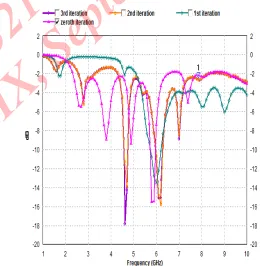
.In this section results of different iterations of cantor fractal geometry applied on square patch antennas are discussed. Figure 3 represents different fractal geometry iterations of reference antenna. Return loss vs. frequency curve for different fractal geometry iterations are shown in figure 3. From figure 3 it is found that fractal geometry helps in improving antenna characteristics. Antenna at zeroth iteration resonates at 2.8 GHz with return loss of -12.55 dB, gain of 2.15 dBi, directivity of 9.09 dBi and bandwidth of 240 MHz By applying first iteration of fractal geometry, antenna resonates at 6 GHz with return loss of -13.59 dB, gain of 2.38 dBi, directivity of 6.55 dBi and
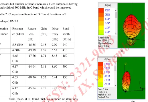
bandwidth of 410 MHz By applying second iteration of fractal geometry, antenna resonates at 4.65 GHz and 6.17 GHz with return loss of -18.76 dB, -12.04 dB, gain of 1.71 dBi and 3.11 dBi, bandwidth of 150 MHz and 320 MHz at corresponding frequencies. When next iteration of fractal geometry is applied, characteristics slightly improves as antenna resonated at two bands namely 4.63 GHz and 6.2 GHz with return loss of -18.76 dB, -12.04 dB and -18.76 dB, gain of 1.52 dBi and 2.78 dBi and directivity of 2.44 dBi and 8.25 dBi Table 2 shows comparison of results of different iterations of cantor fractal geometry applied on square patch as shown in figure 3. These results shows as number of iterations show as number of iterations increased, a characteristic of antenna begins to improve. Results of return loss versus bandwidth showed that antenna characteristics will be good as number of iterations increases in terms of return loss, bandwidth and frequency.
Figure 2.1: Return Loss Vs. Frequency for Different Fractal Iterations of H-Shaped FMPA
[image:4.612.108.221.128.263.2] [image:4.612.315.575.322.588.2]decreases but number of bands increases. Here antenna is having bandwidth of 300 MHz in C band which could be improved
Table 2: Comparison Results of Different Iterations of I
H-shaped FMPA Iteration Number Resonan ce (GHz) Return Loss (dB) Gain (dBi) Direc tivity (dBi) Band width (MHz)
0th 5.8 GHz -15.55 2.15 9.09 240
1st 6 GHz -13.59 2.38 6.55 410
2nd 4.65
GHz
-17.76 1.71 5.48 150
6.17
GHz
-14.04 3.11 8.60 300
3rd 4.65
GHz
-18.76 1.52 5.44 150
6.17
GHz
-15.04 2.78 8.25 320
From these, it is found that, as number of iterations increases, results improves but complexity increases. Radiation pattern corresponding to that of antenna shown in figure 4.2 is shown in figure 2.2. These radiation patterns correspond to that of frequency 4.63 and 6.2 dB as shown in figure 3(a) and 3 (b).
(a)
(b)
Figure 3: Radiation Pattern of Reference Antenna at (a) 4.63 GHz and (b) 6.2 GHz
REFERENCES
[1]
Varadhan C., Pakkathillam J. Kizhekke, KanagasabaiM., Sivasamy R., Natarajan R. and Palaniswamy S. Kumar,
2013. “Triband Antenna structures for RFID Systems
Deploying Fractal Geometry”, IEEE Letters on Antennas and
Wireless Propagation, Vol. 12, pp 437-440.
[2]
Waladi V., Mohammadi N., Zehforoosh Y., HabashiA. and Nourinia J., 2013. “A Novel Modified Star Triangular
Fractal (MSTF) Monopole Antenna for Super Wideband
Applications”, IEEE Letters on Antennas and Wireless
Propagation, Vol. 12, pp 651-654.
[3]
Kakkar S., Priyadarshini and Rani S., 2013. “NewAntenna with Fractal Shaped DGS for Emergency
Management Applications”, International Journal of
Advanced Research in Computer Science and Software Engineering, Vol. 3, Issue 3, pp 721-724.
[4]
Kumar A., Kaur J. and Singh R., 2013. “PerformanceAnalysis of Different Feeding Techniques”, International
Journal of Emerging technology and Advanced Engineering”,
Vol. 3, Issue 3, pp 884-890.
[5]
Behera S. and Vinoy K. J., 2012. “Multi-Port NetworkAntennas”, IEEE Transactions on Antennas and Propagation, Vol. 60, No. 11, pp 5100-5106.
[6]
Ram V., Anjaria V., Boriya P. and Patel N., 2012.“Design and Development of Switchable Fractal Patch
Antenna for GPS Application”, International Journal of
Engineering and Science, Vol. 1, Issue. 7, pp 46-50.
[7]
Moghadasi M. Naser, Sadeghzadeh R. A., Fakheri M.,Aribi T., Sedghi T. and Virdee B.S., 2012. “Miniature Hook
-Shaped Multiband Antenna for Mobile Applications”, IEEE
Letters on Antennas and Wireless Propagation, Vol. 11, pp 1096-1099.
[8]
Oraizi H. and Hedayati S., 2012. “Circular PolarizedMultiband Microstrip Antenna Using the Square and
Giuseppe Peano Fractals”, IEEE Transactions on Antennas
and Propagation, Vol. 60, No. 7, pp 3466-3470.
[9]
Karmakar A., Verma S., Pal M. and Ghatak R., 2012.“An Ultra Wideband Monopole Antenna with Multiple Fractal
Slots with Dual Band Rejection Characteristics”, Progress in
Electromagnetic Research C.”, Vol. 31, pp 185-197.
[10]
Sun Xu-Bao, Cao Mao-Yong, Hao Jian-Jun and GuoYin-Jing, 2012. “A rectangular slot antenna with improved
bandwidth”, International Journal of Electronics and
![Figure 1: Fractal Geometry Algorithm used [5]](https://thumb-us.123doks.com/thumbv2/123dok_us/8587100.862764/3.612.65.199.178.256/figure-fractal-geometry-algorithm-used.webp)