5
IV
April 2017
Technology (IJRASET)
Advanced Arm Based System for Road Safety
B. V. Ramana1, M. Sai Kumar Achari 2, B. Shiva Teja3, D. Mahendra4, E. Kranthi Chaitanya5
1,2,3,4,5
ECE, JNTUA
Abstract: Safe Journey is the important thing while travelling in vehicle. This paper explains about alerting the driver and make the vehicle to stop to prevent accident, if driver consumes alcohol and exceed the speed limit even the vehicle is ahead. The vehicle speed can also be controlled when it enters the over speed zones. Even though the accident occurs after taking the precautions the by using GPS and GSM accident location is send to family members and concerned authorities immediately to rescue them
Keywords : Sensors, GSM, GPS, Accident Detection, Speed Control.
I. INTRODUCTION
The important theme in this paper is to prevent accidents on roads. Accident preventions can be controlled with help of automatic breaking system using ultrasonic sensor. Ultrasonic usually performs to calculate the distance of the ahead vehicle by using ultrasonic waves. The transmitter transmits the wave will reflect when obstacle detected that is vehicle is ahead and received by receiver. The main aim of this paper Is vehicle can automatically apply brake due to presence of obstacles when the sensor detects the obstacles. Presently, many accidents are taking place because of the alcohol consumption of the driver or the person who is driving the vehicle. Major cause of accidents is due to drunk and driving. To avoid it, we have developed, “alcohol detection”. By using alcohol sensor, we can know whether driver consumes alcohol or not. Once it is detected, system will send message to family member. Though we are using these prevention measures, there are some chances for occurring accidents. Today, it is very difficult to find the position of where the accident has occurred. It’s more difficult for the lives of victims until any person know the information and informed it to the emergency vehicles like ambulance or to hospitals and if it occurs in urban areas it will becomes no hope to survive. To avoid these, different technologies like GSM/CDMA and Global positioning systems (GPS are used. The GPS based accident identification module contains a, vibrating sensor and a GPS module connected to the processor unit. If accident occurs vibration sensor gives intimation to micro controller which process information and takes further step, switch on the buzzer unit and sends the information to the ambulance, police and owner/parents through GSM network. The system will also continuously track the location of the vehicle; this will be useful when the user requires current information. The vehicle position can be located with the help of latitude and longitude values which we get the values through mobile. The vehicle speed is also controlled at zone areas using RF transmitter and receiver. The main aim of this project is to identify the vehicle accident and send the location of the accident with the information of vehicle driver.
II. LITERATURE SURVEY
Existing system is an automatic vehicle accident detection system using GSM and GPS modems. The system can be interfaced with the car alarm system and alert the owner on his/her mobile phone. This detection and messaging system operation is carried out by a GSM Modem, Microcontroller and a GPS Receiver. GPS Receiver gets the accident location information from the satellite in the form of longitude and latitude. By using GSM modem the microcontroller will send information to user mobile phones. A GSM modem is interfaced to the MCU with respective pin. The GSM modem sends an SMS to the particular mobile number and informs about the accident, so that the family members or rescue team will save the life of accident people. The system was designed with the AT89S52 micro controller from Atmel.. There are no sensors included for alcohol detection, zone identification and speed control.
III. PROPOSED SYSTEM
Technology (IJRASET)
vehicle is met with accident if collision occurs. The entire operations will be processed by LPC2148 microcontroller and particular operations will be done
A. Implementation
Fig.1. Building Block Diagram
B. Features of LPC2148 Controller
Embedded Artists LPC2148 Education Board with NXP’s ARM7TDMI LPC2148 microcontroller lets you get up-and-running quickly. The small form factor board offers many unique features that ease your learning curve and program development.
1) NXP ARM7TDMI LPC2148 microcontroller with 512 KByte program Flash and 32+8 KByte SRAM
2) 12.0000 MHz crystal for maximum execution speed and standard serial bit rates Phase-locked loop (PLL) multiplies
frequency with five; 5 x 12 MHz = 60 MHz
3) 32.768kHz RTC crystal
4) On board Peripherals
5) 2x16 character LCD with background light
6) Joystick switch
7) UART-to-USB bridge interface on UART #0
8) USB 2.0 device interface (on the LPC2148)
9) RGB-LED, each color can be controlled via PWM sigma
10) 8 LEDs
11) Temperature sensor (LM75) on I 2C bus Pushbutton on P0.14 (interrupt input)
12) 2 Kbit I2C E2PROM for storing non-volatile parameters
13) On board low-dropout voltage and reset generation.
14) Generates +3.3V (and +5V if 9-15VDC is used to power the board)
15) +3.3V available for external circuits, up to 300 Ma
16) Power supply
17) 9-15 VDC, ≥200 mA from 2.1 mm power connector
18) Can also be powered directly from any of mini-B USB connectors
Technology (IJRASET)
C. Alcohol Gas Sensor - MQ-3
Alcohol sensor MQ3 is senses the alcohol content in the vehicle if driver consumes alcohol. Sensor provides an analogy resistive output based on the alcohol concentration. MCU is the Micro Controller Unit which performs operation of each functionality lock present in the system. Alcohol sensor is connected to the MCU through the comparator and the comparator compares the analog value with reference value and send data to MCU. MCU receives data from the comparator and performs operation ,if alcohol content is more it send command to stop the motor
Fig.3. MQ3 Alcohol Sensor
If the alcohol is detected the motor that is connected in NC (Normally closed) mode is turned off indicating that the trigger coil of the relay is energized and the connection in the relay has shifted from NC (Normally Closed) mode to NO (Normally Open) mode.
D. Vibration Sensor
The vibration sensor is used here is a mercury liquid type vibration sensor. If mercury liquid is tilted the vibration sensor which is connected to micro controller will send logic 1 that logic is treated as accident occurred to vehicle ,the micro controller alerts the neighbours on road by alarm and intimate the accident to particular members by sending information as accident occurred with location using GSM and GPS. Vibration sensor plays a major role in this system
Fig.4. Vibration Sensor module
E. Ultrasonic Sensor
HC-SR04 Ultrasonic Sensor is used for distance measuring .it contains 4pins vcc pin, ground pin, trigger pin, echo pin. The range of this sensor is 2 to 4cm. The trigger pin act as transmitter which generates sound waves for every 10 micro seconds. In addition to this 8 micro second clock is generated to increase the echo sound. If any obstacle is ahead the sound waves reflected back and the wave signal was received by echo pin which gives logic 1 for microcontroller to do further operation for prevention in our system especially. If the obstacle is not detected then for every 10 micro second waves are generated simutanously.
Fig.5. HC-SR04 Ultrasonic Sensor module
F. RF Transmitter and Receiver
Technology (IJRASET)
the receiver through transmitter antenna in a serial communication. The receiver section contains the HT12D decoder which decodes the received data and send information to micro controller which performs operation based on information.
Fig.6. RF Transmitter and Receiver Section
G. GSM
A GSM derived named PCS-1990 came into existence with late entry of north America in the GSM market. Now the acronym GSM is “GLOBAL SYSTEM FOR MOBILE COMMUNICATION “. since it is existed in the continent the phase 1 GSM-900 was the first GSM system first developed for only voice and it operates in the frequency band of 900 MHZ, then in the year 1995 phase 2 was put forward the contained facsimile, video, data, communication services along with the voice. Later GSM 1800 and 1900 introduced employing the PCS frequency 1800 MHZ.GSM consists of three major subsystems.
1) Base Station Subsystem
2) Network Switching Subsystem
3) Operation support sub system
H. The Various Accessing Techniques used by GSM are
1) Frequency division multiplexing
2) TDMA.FDMA combination
The outstanding feature of GSM is the subscriber identity module. This is a memory device that stores information like the subscriber identification number, the networks where the subscriber is empowered to the service.
The second outstanding feature of GSM is air privacy ,which is supported by the system . the privacy is attained by the encrypting the digital bit stream, covered by a GSM transmitter, with a specified secret cystography key that is only known to cellular carrier
Fig.7. GSM Module
I. GPS
GPS receiver is the Global Positioning System receiver. It is used to find the accurate position of an object with the help of signals received from the satellite. The parallel multichannel design of GPS receiver helps in finding the position of the body more accurately. The location of an object can be easily found by the GPS receiver using minimum three satellite signals and an extra satellite can be considered to offset the timing error.
The receiver consists of the following units
1) The antenna used for receiving signal is of circularly polarized patch type antenna with a LNA placed over it
2) An IF signal if bandwidth 2 MHZ is generated by the super heterodyne receiver.
3) Sampling and quantization of this signal is done by A/D converter and Digital Signal Processing
4) The timing and accurate measurements are processed by microprocessor and finally the current position of receiver is
Technology (IJRASET)
IV. RESULTS
A. Alcohol Sensor
When alcohol is detected automatically motor will stop and an SMS alert is sent to mobile number
Fig8. Alcohol Detection Condition.
B. Vibration Sensor
If vibration sensor is tilted, it treated as accident occurred and message is sent to respective mobile numbers and buzzer is on to alert people on road.
Fig9. LCD displaying vibration sensor is on and alert message sent to mobile
C. HC-SR04 Ultrasonic Sensor
When the obstacle is ahead the buzzer is on to warn the driver and if he neglects the warning, the motor automatically stops
Fig 10. When no obstacle is ahead speed is maximum Fig11.When obstacle is detected ahead speed is minimum
D. Zonal Area Speed Control
Technology (IJRASET)
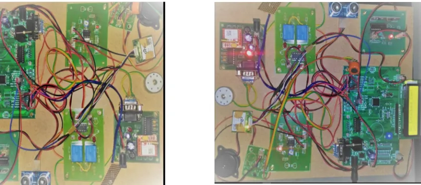
[image:7.612.111.530.98.283.2]Project Kit Screen Shots
Fig 13. Equipment Board
V. CONCLUSION AND FUTURE SCOPE
We are seeing many accidents in newspaper and in Television mainly due to over speeding of vehicle i.e. rash driving and driver drunken state. In order to prevent by implementing the above mentioned sensors in the vehicles with ARM controller one can have a safe journey while travelling. So that many accidents can be reduced on roads. This project is gift for the society to prevent accidents in this crowded environment. Hope this project is of no doubt to save precious life. In future by implementing eye blinking sensor so that if driver feel drowsy it alert the driver.
REFERENCES
[1] Zutao Zhang, Jiashu Zhang, “A Novel Vehicle Safety Model: Vehicle speed Controller under Driver Fatigue”, “IJCSNS International Journal of Computer Science and Network Security”, VOL.9 No.1, Januar [2] M. Bertozzi, A. Broggi, M. Cellario, A. Fascioli, P. Lombardi, and M. Porta, “Artificial vision in road vehicles,” Proceedings of the IEEE, vol. 90, no. 7, pp. 1258–1271, 2002.
[2] S. Tsugawa and Sadayuki, “Vision-based vehicle on japan: Machine vision systems and driving control systems,” IEEE Trans. on Ind. El.???, vol. 41, no. 4, pp. 398–405, 1994.
[3] Vehicle-highway automation activities in the United States. U.S. Dept. of Transportation, 1997.
[4] C. Thorpe, J.D. Carlson, D. Duggins, J. Gowdy, R. MacLachlan, C. Mertz, A. Suppe, and C. Wan, “Safe robot driving in cluttered environments,” 11th International Symposium of Robotics Research, 2003.
[5] Qian Martin Eriksson, Nikolaos P. Papanikolopoulos, Eye-Tracking for Detection of Driver fatigue. Proceedings of the international Conference on intelligent Transportation System, Boston, MA, November 1997, pp.314-319.
[6] Qiang Ji, Zhiwei Zhu, and Peilin Lan, Real-Time Nonintrusive Monitoring and Prediction of Driver Fatigue. IEEE Transactions on Vehicular Technology, VOL. 53, NO. 4, July 2004, pp.1052-1068.
BIBLIOGRAPHIES
Mr. B. V. RAMANA has pursued his B.Tech from St JOHNS college of Engg, & Tech .Yemmiganoor and
M.Tech from Sree Vidyanikethan Engineering College, Tirupathi Presently he is working as Asst.Prof in Dept. of ECE of Brindavan Institute of Technology & Sciences, Kurnool. His research areas of interest are Electronic Circuit Analysis & Design, Linear Integrated Circuit Design, Fault detection and testing of digital circuits,Fault Model Analysis
Mr. M. Sai Kumar Achari is pursuing his B. TECH in Brindavan Institute of Technology & Science. He is from Dept. of ECE from BITS, Kurnool. His research area of interest are Embedded Systems and Wireless
Technology (IJRASET)
Mr. B. Shiva Teja is pursuing his B. TECH in Brindavan Institute of Technology &Science. He is from Dept. of ECE from BITS, Kurnool. His research areas of interest are embedded systems and VLSI Design
Mr. D. Mahendra is pursuing his B. TECH in Brindavan Institute Of Technology &Science. He is from Dept. of ECE from BITS, Kurnool. His research areas of interest in embedded systems and VLSI desi
Mr. E. Kranthi chaitanyaa is pursuing his B.TECH in Brindavan Institute Of Technology &Science. He is from Dept. of ECE from BITS, Kurnool. His research areas of interest in embedded systems and VLSI design