Technology (IJRASET)
CORDIC Based Efficient DCT Architecture for
low power image computation
Mr. Akhil. C. Raj 1, Mr. Navin Y 2
1
M.E VLSI Design, 2Assistant Professor, Department of E C E JCT College of Engineering and Technology, Pichanur, Coimbatore
Abstract: Co-ordinate rotation digital computer (CORDIC) based digital signal processing has become an important tool in the fields of communications, biomedical and industrial production, providing designers with significant impetus for making algorithm into architecture. With the explosive growth of multimedia services running on portable applications, the demand for
low- power implementations of complex signal processing algorithms are tremendously increasing. The most significant part of
multimedia systems are the applications involving image and video processing which are very computationally intensive and thus should be implemented with low cost. In order to reduce power consumption, the CORDIC algorithm can be used. Several methods were combined with the CORDIC algorithm but among them DCT (Discrete Cosine Transform) provide a better performance while processing the images. So the low-power design of discrete cosine transform has been of particular interest, since DCT is one of the most computationally intensive operations in video and image compression, and it is widely adopted in many standards such as JPEG, MPEG, and H.264.CORDIC computation along with the DCT architecture can be used to reduce the power consumption in the image computation. By using the Look ahead CORDIC approach the number of iteration and complexity could be reduce. Hence large amount of power savings can be achieved through the specified method.
Index terms : discrete cosine transform(DCT), coordinate rotate digital computer(CORDIC)
I. INTRODUCTION
The main objective of this paper is to reduce the power consumption of image computation. In VLSI (very large scale integration) design area, power and speed are the main aspects which were used in the designing of the circuit. Among them power consumption plays an important role. The paper proposes an effective method to reduce the power consumption in the portable electronic devices. While considering the portable devices, mobile phones are one among them which consume a high range of power for the operations.
In 1975, the first mobile phones were invented by Mr. Martin cooper under the Motorola organization. After the invention of digital signal processors wide range of evolution is happen in the field of portable devices. Now the smartphones were available in the market, but the power consumption of mobile phones were increased in a high peak range. Reducing the consumption of power will become one of the major problems. Considering power consumption areas of mobile phones, image computation power will be high. So the main idea is to reduce the power consumption at the time of image computation.
Different types of methods were available to reduce the power consumption. For the JPEG (joint picture expert group) DCT (discrete cosine transforms) is used to reduce the image computation power. But the DCT have an efficient architecture for that. Architecture can be created by using an algorithm. CORDIC (coordinate rotation digital computer) can be used along with DCT. As the name implies CORDIC has a rotation matrix which coordinately rotate to form DCT coefficients .the main advantage of CORDIC is that it can be implemented by using the shifters and adders. Hence possess less cost.
DCT use the low frequency component alone. The high frequency components were neglected. But through this the efficient of the system become reduced. Paper proposes the 2d DCT architecture which can be used as the 1d DCT row and column wise.
CORDIC (coordinate rotate digital computer) is an hardware efficient algorithm. It helps to compute the sin, cos, tan, sinh, cosh and tanh. It is an iterative algorithm for circular rotation. Co-ordinate rotation digital computer based digital signal processing has become an important tool in the fields of communications, biomedical and industrial production, providing designers with significant impetus for making algorithm into architecture. With the explosive growth of multimedia services running on portable applications, the demand for low- power implementations of complex signal processing algorithms are tremendously increasing. The basic principal of CORDIC is to iteratively rotate a vector using a rotation matrix, which is represented as follows
where x and y are the vector coordinate components of x and y axes, respectively, i is the I th iteration step, σ is the sign-bit that can be +1 or−1 indicating the direction of the vector rotation, z is the accumulated rotation angle, and α is the predefined angle value of each micro rotation step, αi = arctan(21−i). In the CORDIC architecture, the amplitude and argument of a given vector can be calculated using the vectoring mode, while the sine and cosine values of the given angle are obtained with the rotation mode.
III. CORDIC-BASED DCT ARCHITECTURE
Now, DCT can be implemented using only shifters and adders without multiplier. Please note that the sign-bits and the scale-factor are known ahead since the input angles of CORDIC module are given as the DCT bases.
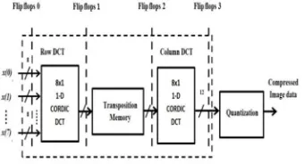
[image:3.612.242.412.376.468.2]The 2-D DCT process is decomposed into an 1-D DCT (row DCT) followed by another 1-D DCT (column DCT),The 2-D DCT process with separable 1-D DCT is shown in Fig .2
Fig .1. DCT processor with separable 1-D DCT.
For different tradeoff modes, the proposed DCT architecture can be dynamically reconfigured by simply changing the control signal _ to tradeoff minor image quality for computation energy. Once a tradeoff mode is determined, the control signal _ controls the turnoff gate arrays for both of the CORDIC equation terms and the scaling terms. It is noteworthy that the proposed architecture and the design parameters can be changed according to the required amount of power savings.
By coordinating the CORDIC and DCT method is proposed but while processing it, the numbers of iteration become increased due to satisfy the needs. Through this the number of disadvantages becomes happened. In this number of hardware used, power consumption also increases. Let’s take the example calculation of the second iteration it depends output of the first iteration leads to the creation of the specific crossing architecture. This architecture increases the complexity.
Technology (IJRASET)
The main idea in this paper is based on the fact that low-frequency DCT coefficients are relatively more important than high-frequency coefficients. Our CORDIC-based DCT architecture is designed considering the importance differences between the low and high-frequency DCT coefficients. Generally, as the more number of iterations is performed in CORDIC, the more accurate results are obtained. Therefore, in the proposed DCT architecture, a larger number of CORDIC iterations are assigned to generate the low frequency DCT coefficients, whereas the relatively smaller number of iterations are used for the high-frequency components. The number of CORDIC iterations is judiciously selected such that the image quality degradation because of the smaller iterations can be minimized.
In the CORDIC equation, to calculate the output of the current stage, the results from the previous stage iterations should be computed first. These data dependencies are the main performance bottleneck in the conventional CORDIC hardware. To get over the data dependencies, lookahead CORDIC is developed, where lookahead means that a number of CORDIC iterations can be computed ahead to finish the iterations at one time.
The discrete cosine transform have higher consistency while compare with the other transforms. The quantization is used to equalize the pixel value values in the out coming images which helps the computation process.
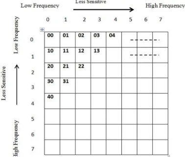
After 2-D DCT operation, the input data in space domain is transformed to the frequency domain, which is the 8 × 8 block of 64 DCT coefficients shown in Fig..3
[image:4.612.71.260.420.580.2]
Fig .2. Sensitivity difference of 2-D coefficients.
(1) in (8)) are more important than the shift terms for calculating high-frequency coefficients. Additionally, among the shift-terms in one lookahead CORDIC equation, the most important terms are low shift-terms while the relatively less important terms are high terms. To save the computation power at the expense of minimum image quality degradation, first, the least important shift-term in X (7) is removed based on Greedy algorithm . Again, we search for the next least important shift-shift-term to cancel the computation. As we repeat the process, the more number of shift-terms are removed, which means that the computation power is reduced with minimum image quality degradation.
DCT has the signal compaction property, the signal energy of the output data (DCT coefficients) is mostly concentrated on a few low-frequency components, while the other higher frequency components are associated with small signal energy. The high-frequency DCT coefficients become even smaller after the quantization step , which means that the low high-frequency components (DC) are more sensitive to human eyes than high-frequency components.
Here, as DCT has the signal compaction property, the signal energy of the output data (DCT coefficients) is mostly concentrated on a few low-frequency components, while the other higher frequency components are associated with small signal energy. The high-frequency DCT coefficients become even smaller after the quantization step , which means that the low high-frequency components (DC) are more sensitive to human eyes than high-frequency components.
IV. PROPOSED METHOD
CORDIC (for Coordinate Rotation Digital Computer), also known as the digit-by-digit method and Volder's algorithm, is a simple and efficient algorithm to calculate hyperbolic and trigonometric functions. It is commonly used when no hardware multiplier is available (e.g., simple microcontrollers and FPGAs) as the only operations it requires are addition, subtraction, bit shift and table lookup.
The modern CORDIC algorithm was first described in 1959 by Jack E. Volder. It was developed at the aero electronics department of Convair to replace the analog resolver in the B-58 bomber's navigation computer. Originally, CORDIC was implemented using the binary numeral system. In the 1970s, decimal CORDIC became widely used in pocket calculators, most of which operate in binary- coded-decimal (BCD) rather than binary. As this was only a change in the input and output method, and not the calculation method these changes did not alter the core CORDIC algorithms.
CORDIC is particularly well-suited for handheld calculators, an application for which cost is much more important than speed (namely the chip gate count must be minimized). Also the CORDIC subroutines for trigonometric and hyperbolic functions can share most of their code, due to the common behaviors of these functions. CORDIC has been implemented in the cores of some x86 CPUs for some kinds of floating point instructions, mainly as a way to reduce the gate counts (and complexity) of the FPU subsystem.
Many older systems with integer-only CPUs have implemented CORDIC to varying extents as part of their IEEE Floating Point libraries. As most modern general-purpose CPUs have floating-point registers with common operations such as add, subtract, multiply, divide, sin, cos, square root, log10, natural log, the need to implement CORDIC in them with software is nearly non-existent. Only microcontroller or special safety and time-constrained software applications would need to consider using CORDIC. CORDIC uses simple shift-add operations for several computing tasks such as the calculation of trigonometric, hyperbolic and logarithmic functions, real and complex multiplications, division, square-root calculation, solution of linear systems, eigen value estimation, singular value decomposition, QR factorization and many others. As a consequence, CORDIC has been utilized for applications in diverse areas such as signal and image processing, communication systems, robotics and 3-D graphics apart from general scientific and technical computation.
CORDIC is generally faster than other approaches when a hardware multiplier is not available (e.g., a microcontroller), or when the number of gates required to implement the functions it supports should be minimized (e.g., in an FPGA).On the other hand, when a hardware multiplier is available (e.g., in a DSP microprocessor), table-lookup methods and power series are generally faster than CORDIC. In recent years, the CORDIC algorithm has been used extensively for various biomedical applications, especially in FPGA implementations.
CORDIC is part of the class of "shift-and-add" algorithms, as are the logarithm and exponential algorithms derived from Henry Briggs' work. Another shift-and-add algorithm which can be used for computing many elementary functions is the BKM algorithm, which is a generalization of the logarithm and exponential algorithms to the complex plane. For instance, BKM can be used to
Technology (IJRASET)
The BKM algorithm is slightly more complex than CORDIC, but has the advantage that it does not need a scaling factor (K).
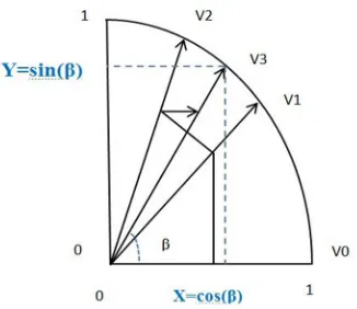
Using CORDIC, we would start with the vector
[image:6.612.68.231.144.285.2]
Figure .3. CORDIC graph
In the first iteration, this vector is rotated 45° counterclockwise to get the vector. Successive iterations rotate the vector in one or the other direction by size-decreasing steps, until the desired angle has been achieved. Step i size is arctan(1/(2i−1)) for i = 1, 2, 3, ….
More formally, every iteration calculates a rotation, which is performed by multiplying the vector with the rotation matrix
The rotation matrix is given by,
Using the following two trigonometric identities
The expression then becomes,
which is calculated in advance and stored in a table, or as a single constant if the number of iterations is fixed. This correction could
also be made in advance, by scaling and hence saving a multiplication.
After a sufficient number of iterations, the vector's angle will be close to the wanted angle . For most ordinary purposes, 40 iterations (n = 40) is sufficient to obtain the correct result to the 10th decimal place. The only task left is to determine if the rotation should be clockwise or counterclockwise at each iteration.This is done by keeping track of how much the angle was rotated at each
iteration and subtracting that from the wanted angle; then in order to get closer to the wanted angle , if is positive, the
rotation is clockwise, otherwise it is negative and the rotation is counterclockwise.
The rotation-mode algorithm described above can rotate any vector (not only a unit vector aligned along the x axis) by an angle
between –90° and +90°. Decisions on the direction of the rotation depend on being positive or negative. The vectoring-mode of
operation requires a slight modification of the algorithm. It starts with a vector the x coordinate of which is positive and the y coordinate is arbitrary. Successive rotations have the goal of rotating the vector to the x axis (and therefore reducing the y
coordinate to zero). At each step, the value of y determines the direction of the rotation. The final value of contains the total angle of rotation. The final value of x will be the magnitude of the original vector scaled by K. So, an obvious use of the vectoring mode is the transformation from rectangular to polar coordinates.
In this a look ahead CORDIC approach is introduced, which have the number of iterations. In the initial stage itself the approach produce the respective shift component which is needed for the specific iteration and also the iteration become predetermined. Through this the crossing architecture may avoided hence complexity become reduced and the power consumption get reduced.
Technology (IJRASET)
Figure .4. Block diagram
Let’s have a brief discussion about the block diagram
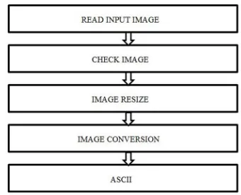
[image:8.612.76.246.163.301.2]A. Input to ASCII conversion
Figure .5. input to ASCII conversion
Input image is given to the system. The system will check the image. The size and the type of the image become checked. If the size is not tolerable with the appropriate size, then it would be resized through the next block. The resized image is processed and then the conversion is began and the ASCII (American standard code for information interchange) converted image is stored as the output.
B. Temporary memory
ROM (read only memory) is used as the temporary memory. It has two sections. One is to store the ASCII code and the next one is to store the processed output.
C. Arithmetic and computation unit
Carry select adder is used for the addition and multiplication because carry select adder have lesser complexity than the other adders. Unit performs addition multiplication and division. For the first section it may take the 1-D DCT and the next computation process it may take next part of the DCT.
D. Discrete Cosine Transform
A discrete cosine transform (DCT) expresses a finite sequence of data points in terms of a sum of cosine functions oscillating at different frequencies. DCTs are important to numerous applications in science and engineering, from lossy compression of audio (e.g. MP3) and images (e.g. JPEG) (where small high-frequency components can be discarded), to spectral methods for the numerical solution of partial differential equations. The use of cosine rather than sine functions is critical for compression, since it turns out (as described below) that fewer cosine functions are needed to approximate a typical signal, whereas for differential equations the cosines express a particular choice of boundary conditions.
in which the element (top-left) is the DC (zero-frequency) component and entries with increasing vertical and horizontal index values represent higher vertical and horizontal spatial frequencies.
The most common variant of discrete cosine transform is the type-II DCT, which is often called simply "the DCT", its inverse, the type-III DCT, is correspondingly often called simply "the inverse DCT" or "the IDCT". Two related transforms are the Discrete Sine Transform (DST), which is equivalent to a DFT of real and odd functions, and the modified discrete cosine transform (MDCT), which is based on a DCT of overlapping data. It is shown that the discrete cosine transform can be used in the area of digital processing for the purposes of pattern recognition and Wiener filtering. Its performance is compared with that of a class of type. The DCT-II formula is applied to each row and column of the block. The result is an 8 × 8 transform coefficient array in which the
element (top-left) is the DC (zero-frequency) component and entries with increasing vertical and horizontal index values represent higher vertical and horizontal spatial frequencies.
E. Quantization
It is used to eliminate errors in the processed output. Any variation of the output from the expected will be automatically corrected by the quantizer. Here it eliminates the changes in output of 2-D DCT. It acts as a filter.
F. Encryption And Decryption Unit
The block is added for the data security purpose. Cypher key is used for the encryption and decryption process.
V. CONCLUSION
In the conventional DCT architecture, all the computations are not equally important in generating the frequency domain outputs. This paper presented a low-power CORDIC based DCT architecture, where the importance differences in DCT coefficients were efficiently exploited to allocate the numbers of CORDIC iterations and internal data bit-widths. Lookahead CORDIC architectures were effectively used to get over the inherent data-dependencies in the conventional crossing-architecture of CORDIC. The proposed reconfigurable CORDIC-based DCT architecture can dynamically change the tradeoff modes with the power savings compared with the CORDIC-based Loeffler DCT architecture.
REFERENCES
[1] B vennala and k santhosh kumar “Design of NCO by Using CORDIC Algorithm in ASIC-FPGA Technology” issn 2231-1297, vol 3, no. 9, pp 1109-1114, nov 2013.
[2] C. Sun, S. J. Ruan, B. Heyne, and J. Goetze, “Low-power and high- quality CORDIC-based Loeffler DCT for signal processing,” IET Cir- cuits, Devices, Syst., vol. 1, no. 6, pp. 453–461, Dec. 2007
[3] D. L. Gall, “MPEG: A video compression standard for multimedia applications,” Commun. ACM, vol. 34, no. 4, pp. 46–58, Apr. 1991.
[4] G karokonstantis , Banerjee. N and roy k “Process-Variation Resilient and Voltage-Scalable DCT Architecture for Robust Low-Power Computing ” IEEE Trans. vlsi., vol. 18, no. 10, pp. 1461-1470, nov 2013
[5] G. K. Wallace, “The JPEG still picture compression standard,”IEEE Trans. Consum. Electron., vol. 38, no. 1, pp. 18–34, Feb. 1992 [6] J. E. Volder, “The CORDIC trigonometric computing technique,” IRE Trans. Electron. Comput., vol. 8, no. 3, pp. 330–334, Sep. 1959.
[7] Jongsun Parle, Young Hwanchoi and Kaushik Roy “Dynamic Bit-Width Adaptation in DCT: An Approach to Trade Off Image Quality and Computation Energy” issn 1211-1197, vol 6, no. 15, pp 1205-1209, nov 2014
[8] K Sreekanth yadav , V Charishma and Neelima “Design and simulation of 64 point FFT using Radix 4 algorithm for FPGA Implementation”international journal of engineering trends and technology, vol 4, issue no.2,nov 2013
[9] M. Parlak and I. Hamzaoglu, “Low power H.264 deblocking filterhardware implementations,” IEEE Trans. Consum. Electron., vol. 54,no. 2, pp. 808–816, May 2008.
[10] N. Ahmed, T. Natarajan, and K. R. Rao, “Discrete cosine transform,”IEEE Trans. Comput., vol. 23, no. 1, pp. 90–93, Jan. 1974. [11] N. Prasanna “CORDIC Iterations based Architecture for Low Power and High Quality DCT” issn ,vol 17,issue 4, pp 213,may 2014
[12] S. Hsiao, Y. Hu, T. Juang, and C. Lee, “Efficient VLSI imple- mentations of fast multiplierless approximated DCT using parameter- ized hardware modules for silicon intellectual property design,” IEEE Trans. Circuits Syst. I, Reg. Papers, vol. 52, no. 8, pp. 1568–1579, Aug. 2005.
[13] S. Wang and E. E. Swartzlander, “Merged CORDIC algorithm,” in Proc. IEEE Int. Symp. Circuits Syst., May 1995, pp. 1988–1991.
[14] T. Liu, T. Lin, S. Wang, and C. Lee, “A low-power dual-mode video decoder for mobile applications,” IEEE Commun. Mag., vol. 44, no. 8, pp. 119–126, Aug. 2006.
[15] T. Sung, Y. Shieh, C. Yu, and H. Hsin, “High-efficiency and low-Power architectures for 2-D DCT and IDCT based on CORDIC rotation,” in Proc. Int. Parallel Distrib. Comput. Appl. Technol., Dec. 2006, pp. 191-196.