Modeling data communication with NS3 simulator
Farruh Muzafarov1, Javlonbek Abdujalilov2
Department of Telecommunication engineering, Tashkent University of Information Technologies
Abstract – there are many reasons that simulations are useful in the study and development of computer networks. For large-scale networks, such as huge networks, deployments are expensive and cover very large areas, making simulation models very important both for development and planning purposes. NS-3 has been developed to provide an open, extensible network simulation platform, for networking research and education. In brief, NS-3 provides models of how packet data networks work and perform, and provides a simulation engine for users to conduct simulation experiments. Some of the reasons to use NS-3 include to perform studies that are more difficult or not possible to perform with real systems, to study system behavior in a highly controlled, reproducible environment, and to learn about how networks work.
Keywords – NS-3, Physical layer, Address Resolution Protocol (ARP), User Datagram Protocol (UDP), and TCP.
I. INTRODUCTION
NS-3 is discrete event network simulators. This means that the simulation consists of a series of independent events that change the state of the simulation. Events are actions such as a packet being sent, a new node being added to the network, or a timer expiring. Each scheduled event runs until completion without advancing the simulation time, and then the simulation time is increased to the start time for the next scheduled event.
In both simulators, there is a core consisting of a scheduler and several useful classes defining nodes on a network, packets, and other similarly near-universal concepts. Various models use portions of this core package to implement specific network types, such as WiMAX, or simple wired Ethernet networks. Scripts then define network topologies of nodes connected using the networks defined in these models, and generate traffic between them. [1]
However, while share this very basic architecture, they are very different. NS-2 is based heavily on the original NS, which started development in 1989 [5]. The architecture is starting to show it’s age, and NS-3 was designed to avoid problems caused it [4]. Because the architecture changes are so significant, a decision was made to start from scratch rather than trying to update NS-2. This has resulted in a completely incompatible package that should be considered a successor to NS-2, rather than an evolution of it [3], and porting a NS-2 based model to NS-3 is an involved process. Significant differences include the programming languages used for development [7], the addition of a smart-object and memory management system [6], a more efficient and realistic data storage and packet system [6], a more realistic Node model [4], notable improvements to both memory usage and computational requirements to run a simulation [8], support for industry standard trace files [3], and support for standard application interfaces such as POSIX sockets [4].
II. RELATED WORK
NS-3 basics to get started using in laboratory of telecommunication subjects. The models that are present in ns-3 cover many more layers of the protocol stack: the most current version of ns-3 supports a complete IPv4, Address Resolution Protocol (ARP), User Datagram Protocol (UDP), and TCP stack. ns-3 contains a few simple models to generate and collect trace but more importantly provides many MAC and Physical (PHY) layers. The oldest such model is a detailed IEEE 802.11 implementation that features both infrastructure and ad-hoc mode, multiple rate control algorithms, interference and propagation loss models, many classic mobility models such as random walk, random direction, etc. More recent additions include a Wimax model, a model of underwater communication systems, and a spectrum-aware channel and PHY modeling framework.
III. SIMULATION OF NETWORK TOPOLOGY AND ARCHITECTURE
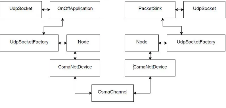
[image:3.612.109.507.153.343.2]For efficiency and performance reasons, the other protocol interfaces have not yet converged to a simple set of common features. For example, the interface between the UDP and the IP layer exposes a lot of details of the IP layer to optimize the case where IP datagrams need to be fragmented to make sure that the UDP layer does not allocate a big buffer to hold the user datagram only to create later a set of smaller fragments in the IP layer.
Fig 1. An ns-3 Network topology
Figure 1 summarizes the relationship between these objects and illustrates how a simple network simulation could be put together to simulate a single link interconnecting a node that sends traffic with a node that receives it. The NetDevice class is based on the Linux kernel-level net device data structure: it represents a single hardware device and allows the upper layers to queue packets for transmission by the hardware and makes it possible for the hardware device to notify the upper layers that a new packet has been received. The NetDevice class is based on the Linux kernel-level net device data structure: it represents a single hardware device and allows the upper layers to queue packets for transmission by the hardware and makes it possible for the hardware device to notify the upper layers that a new packet has been received.
A. Channels interconnect NetDevices
Each Channel object contains the list of NetDevice objects it is connected to. It represents a network cable, a wireless transmission medium, or a fiber cable.
B. The Node class matches the GTNetS concept of a host system. A Node contains a list of NetDevice and Application objects.
C. The Socket class represents a communication endpoint that can be created by applications and that are used to send and receive traffic to the protocol stacks that are attached to a node.
D. The SocketFactory class can be used to create sockets of various kinds by applications: each protocol that is attached (aggregated) to a node needs to also aggregate a new type of SocketFactory to the node so that applications interested in sending or receiving traffic cover this new protocol can request this socket factory and create sockets from it.
ns-3 adopts a similar structure: most inter-layer interfaces except for the socket and net device abstractions are left unspecified to leave as much flexibility as possible to model developers, yet make it easy to inter operate with protocol implementations that expect a socket or a net_device interference to be present. Nodes may/may not have mobility, other traits. Nodes have “network devices”. the motherboard of a computer with RAM, CPU, and, IO interfaces:
– Network devices transfer packets over channels
– Incorporating Layer 1 (Physical) & Layer 2 (Link)
1) Devices interface w/ Layer 3 (Network: IP, ARP)
2) Layer 3 supports Layer 4 (Transport: UDP, TCP)
3) Layer 4 is used by Layer 5 (Application) objects. The packet generator and consumer which can run on a Node and talk to a set
4) Socket: the interface between an application and a network stack.
5) NetDevice: a network card which can be plugged in an IO interface of a Node
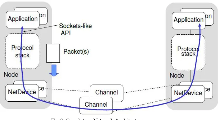
[image:4.612.139.513.126.332.2]6) Channel: a physical connector between a set of NetDevice objects
Fig 2. Simulation Network Architecture
ns-3 is a discrete-event network simulator in which the simulation core and models are implemented in C++. ns-3 is built as a library which may be statically or dynamically linked to a C++ main program that defines the simulation topology and starts the simulator.
IV. NETWORK DESIGN AND CONFIGURATION
[image:4.612.76.541.467.666.2]When you create new topology is being set into the various phases: first you have to choose how many nodes you want to create then you have to install few things on that nodes, like you have to choose the channels, set the attributes on that channel, and then on that channel you have to install few devices, set few rules for those devices which are the internet rules, like protocols and all of that. After that you can do client-server communication and whatever you want to do.
Fig 3. Simulation between client and server using point-to-point channel
V. SIMULATION RESULTS
client to server. Client sent 1024 bytes to server's port 9 at time 2 second and server received at a time 2.00369 second from client.
Fig.4 Client sent 1024 bytes to server
Fig.5 Server received 1024 bytes from client
At time 2s client sent 1024 bytes to 10.1.1.2 port 9
At time 2.00369s server received 1024 bytes from 10.1.1.1 port 49153
At time 2.00737s client received 1024 bytes from 10.1.1.2 port 9
When we run the simulation using NetAnim animation tool we can see the two nodes exchanges data between each other. In the simulation we can see time consumed for transmitting data between hosts.
VI. CONCLUSION
In this paper as a result in our simple point-to-point link model in ns-3, we saw the logging component on the echo client indicate that it was sent one 1024 byte packet to the Echo Server on 10.1.1.2. We also provided the logging component on the echo server say that it has received the 1024 bytes from 10.1.1.1. The echo server silently echoes the packet and we saw the echo client log that it has received its packet back from the server. Simulation is a key component of network research.
REFERENCES
[1] Gustavo Carneiro, “NS-3: Network Simulator 3.” UTM Lab Meeting April 20, 2010. http://www.nsnam.org/tutorials/NS-3-LABMEETING-1.pdf
[2] Joe Kopena, “NS-3 Overview,” March 19, 2008. http://www.nsnam.org/docs/ns-3-overview.pdf
[3] Kevin Fall (Ed), Kannan Varadhan (Ed), “The NS-2 Manual,” 2010. http://www.isi.edu/nsnam/ns/ns-documentation.html
[4] “The NS-3 Manual,” The NS-3 Project, 2010. http://www.nsnam.org/docs/release /3.10/manual /singlehtml /index.html
[5] “The NS-3 Tutorial,” The NS-3 Project, 2010. http://www.nsnam.org/docs/release/3.10/tutorial/singlehtml/index.html
[6] Wlia Weingärtner, Hendrik Vom Lehn, Klaus Wehrle, “A Performance Comparison of Recent Network Simulators”, Proceedings of the 2009 IEEE International Conference on Communications
[7] ns-3 Tutorial Hands-On: Point-to-point and CSMA -Ethernet. 2011/ http://iwing.cpe.ku.ac.th