Technology (IJRASET)
A Current Sharing Method for Paralleled DC-DC
Converter with Parameter Estimation
Visampally Jyothirani1, Durgam Kumara Swamy2, Boini Rajendar3
1,2,3
Dept. of EEE , SVS Institute of Technology, Warangal, Telangana, India
Abstract—In this paper, a new current sharing technique on a general case of N paralleled DC–DC boost converters is presented. The proposed optimization is based on the knowledge of individual boost parameters. Every loss through the structure are modeled by equivalent resistors. Using an accurate online estimation of those resistors, the losses through each individual converter can be determined. Then, a new current sharing scheme is defined aiming to maximize the global efficiency of the overall structure. To verify the proposed method, simulations and experiments have been realized on a three-parallel boost converters structure.
Index Terms—Boost converters, current-sharing, parallel converters, parameter estimation.
I. INTRODUCTION
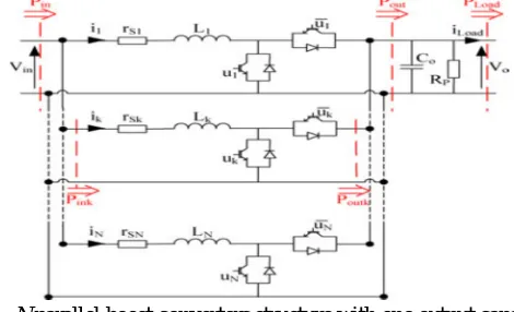
[image:2.612.188.423.507.650.2]PARALLELING dc–dc converters is widely used since it leads to many desirable features [1]. First, paralleling dc–dc converters allows a reduction of the size of components, especially inductive ones. It also reduces stress among individual converters by segmenting the total power, leading to a better global efficiency. Furthermore, this leads to an enhanced reliability, and allows possible reconfigurations when one or more of the paralleled modules present malfunctioning. In nonisolated applications, the boost converter is one of the most used since it is well known and allows good efficiency. In this paper, an N parallel boost converters structure with one output capacitor is considered, as shown in Fig. 1. A good reliability of energy conversion is always needed. By diagnosing the fault in its early stages, the reliability of the power conversion system can be increased significantly [2]. To achieve this, it is very interesting to develop an efficient online parameter estimation. Many parameter estimation techniques have already been proposed for dc–dc boost converters. For example, in [3] and [4] a method to estimate inductance, capacitor, capacitor serial resistance, and load is presented. One of the main disadvantages of the proposed technique, as for those proposed in [5] and [6], is that it requires a sampling frequency much higher than switching frequency. For the present application, the sampling frequency is kept equal to the switching frequency. For this reason, Shahin et al. In most of the literature, the current repartition is only designed in order to allow the system to work. However, as it will be underline in this paper, the repartition can influence on the global structure efficiency. Classically, this is not taken into account. In this aim, the new sharing scheme proposed in this paper allows us to maximize the global efficiency of the overall structure.
Fig. 1. N parallel boost converters structure with one output capacitor.
II. STRUCTURE MODELING AND ESTIMATION
A. Model Of The Structure
Technology (IJRASET)
work. In this paper, it is proposed to model losses through a boost converter by adding N serial and one parallel resistors in the conventional ideal model. For the considered application, each individual boost converter model has a serial resistance rsk, while a
unique parallel resistor Rp includes all the rest of the losses for the whole structure. This difference with the method proposed comes from the nature of the structure with only one output capacitor and one output current sensor. The next section details the method to obtain an accurate online estimation of the resistor values
where dk represents the duty cycle corresponding to the PWM output signal uk . Even if the adopted loss modeling is only
represented through resistors, it is useful to underline that not only ohmic losses are taken into account. In fact, every loss through the converter is taken into account with those of equivalent resistors, such as core hysteresis and eddy current losses, conduction ohmic losses, and switching losses of semiconductors. Particularly, the parallel resistor Rpdoes not only represent the capacitor Co
losses through its ESR. Indeed, it is well known the even under zero power, boost converters still present losses, which will be taken into account through parameter Rpwhile serial resistor is not able to model this behavior. Finally, parameters Rskand Rprepresent
the overall losses through the structure. This will be verified in the experimental part by checking that calculated losses correspond to easurement. For a more detail description of this loss modeling technique, the reader is invited to read reference, where analytical study is presented, as well has load dependence behavior of such a modeling in the case of a single-boost converter. It has to be noticed that the estimation of losses through the converters can also been used for others purpose. As an example, it can be used for verifying the ageing of the individual converters by checking on the variations of the estimated equivalent resistors. This aspect cannot be developed in this paper since it is not its goal, but reader is again invited to read for more details on the estimation.
B. Parameters Online Estimation
Before designing control laws and current-sharing technique, the system parameters need to be estimated. This has to be realized by considering online sampled signals, namely, Vin, ik, Vo and iLoad . It is possible to estimate the equivalent loss resistors following (2)
and (4). Considering that the input power follows its reference Pin = Pin ref∀t, serial resistors will be estimated through (2). This
condition will be ensured with the current regulation presented in Section III
WherepowerPoutk and estimated power follow(3), and λsk convergence coefficients corresponding to serial resistor rsk
Then, considering the output voltage perfectly regulated (Vo = V refo∀t), the parallel resistor will be estimated through (4). This conditionwill be ensured through the energy regulation presented in the following section
Where current id = _k (1 − dk ) ik , estimated currentˆid = iLoad + VoˆRp, and λp convergence coefficient for parallel resistor Rp .
C. Stability Of The Estimation
[image:3.612.193.417.630.693.2]Exponential stability can be proved easily with the classical Lyapunov approach . The stability and dynamics of the proposed estimations are determined by coefficients λsk and λp . In order to demonstrate their stability, the Lyapunov candidate
Technology (IJRASET)
functions following (5) are defined as
For a positive input power, their derivative can be expressed through (6)
The derivatives of Lyapunov functions (6) can be simplified in view of (2) and (4), leading to (7)
Then, by choosing those two parameters positive, it is demonstrated that the estimation errors exponentially converge to 0.
III. CONTROL DESIGN
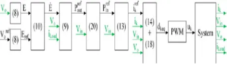
To ensure the control of the structure, it has been decided to design a two-loop control scheme. A first controller enables voltage regulation through energy control. It is based on flatness control method. A second-loop controller, based on sliding method, ensure the current regulation for each individual converter. The proposed control strategy ensures asymptotic stability, robustness against parameter variations, and high dynamics regulation. A block schematic of the entire control is given in Fig. 2.
A. Energy Control Loop Based On Flatness
Flatness was firstly defined by Fliess et al. using the formalism of differential algebra. It has been decided to indirectly control the output voltage Vo by regulating the energy E (8) stored in the capacitor Co . As detailed in and, it is possible to demonstrate that E
is a flat output for the considered system in view of (1a) and (1b)
To obtain a relationship between the input current references irefk and the flat output system E, the derivative ˙E is considered as
To ensure reference tracking, a second-order control law as (10) is proposed to cancel the static error
The power Pout is given as follows:
The parameters αkare power repartition coefficients. In the next section, a new current-sharing scheme aiming to maximize the
overall efficiency will be detailed as a function of the parameters αk. However, in order to transfer the needed power through the
structure, repartition coefficients must follow:
Finally, current references are deduced from (13). Parameter Pref in of this equation will be defined in Section IV
B. Current Loops Design—A Sliding Approach
Technology (IJRASET)
inductor variations is underlined and guaranteed. For each individual boost converter, the sliding surface Sk is defined as follows:
The current ik will follow its reference irefk if the derivative of the surface Sk verify
Equations (14) and (15) can be expressed as
where Kik and λik are the current regulation parameters and Comparing (16) with a second-order law, it is
possible to express current regulation pulsation ωI as
By combining (1) and (15), it is possible to determine the equivalent duty cycle dke q allowing a good reference tracking
C. Regulation Parameters
For simulations and experimental validation, the switching frequency is set to fs = 20 kHz. Table I shows parameters of the controllers. Parameters ωik are chosen in order to verify (19) which is necessary to ensure the validity of the used mean model. In a two-loop control scheme, dynamics of the regulation
must be separated, then ωnE is chosen in order to satisfy
IV. REFERENCE POWER REPARTITION METHOD
By combining (9) and (11), the energy regulation gives the expression (20) of the total input power reference Pref in as a function of repartition parameters αk, with Pref out calculated from (9) as shown in Fig. 2
Technology (IJRASET)
proposed method appears easily compared to the most used currentsharing technique. Therefore, it is needed to determine the repar-tition parameters αk,, so that the input power reference Prefin is minimum for a given load reference Prefout . In view of (12), Prefin
is a function of N −1 parameters. Minimizing this reference power leads to solve
The optimal values of parameters αk minimizing the input reference power can be expressed as (22), presenting the advantage to be quite simple and so easily implementable. Under low power, parameters rsk can not be precisely defined (they tend to infinite for zero current). In this case, it is chosen to stop N – 1 converters and uses only one
Then, knowing parameters αk, the input power reference is calculated from (20) so that it is possible to find current references for
each individual converter as (13). If the parallel converters have strictly the same parameters, the proposed repartition leads to equal current references αk= 1N . Themain interest in the proposed method appears when one converter or more present a lower efficiency
compared to the others (resulting in differences on the estimated parameters rsk ). In this case, the proposed repartition leads to a lower current reference for the less efficient converter, leading to a benefit on the global efficiency. Finally, before presenting simulation and experimental validation lets underline requirements for practical application of the proposed method. First, while measuring some precautions must be taken into account but such requirements are among the classical thematic of digital control, and the proposed technique does not require more accurate measurement than classically used for controlling similar power conversion structures. Second, in term of computational resources, it is obvious that this current-sharing strategy requires more than a simple equal sharing. However, additional calculations are quite simple and the additional required computation time is not important. Then, in most of the cases, implementing the proposed technique will not require to be changed the digital controller for an improved one.
Technology (IJRASET)
V. SIMULATION RESULTS
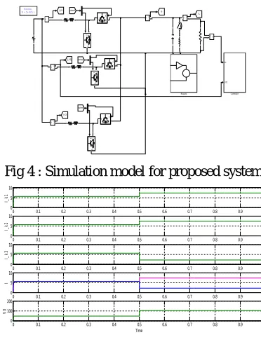
Simulation on three-parallel boost converters have been realized to verify the effectiveness of the proposed method. First, the current repartition is set to αk= 13 . At time t = 0.5 s, the proposed power repartition is enabled. Parameters taken for simulation are
the same as those listed in Table II for experimental verification. Serial and parallel resistors of the simulated model are chosen constant for an easier computation. To validate our purpose, the simulated paralleled boost converters on which the proposed control is applied present different efficiencies for each individual converter. This is simulated by imposing rs1 = 0.39 Ω, rs2 = 0.39Ω, and
rs3 = 1.40Ω traducing more losses through the third individual converter. This difference between serial resistors is only one modeling of a poorer behavior of the third converter. On a real boost converter, many reasons can lead to such results, as many different losses are taken into account through this resistor (see Section II-A and reference for more details). First, it is ensured that the estimated resistors converge to their simulated values. Then, from (22), it is possible to calculate optimal repartition coefficients as
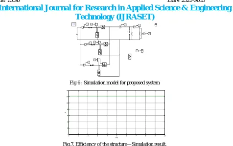
This results on different current references for each converter. Fig. 5 shows current on the previously described control scheme. Fig. 7 shows the efficiency of the structure. In this figure, the efficiency of the proposed current-sharing scheme can be observed. Indeed, when total power is equally divide through elements (t < 0.5 s), efficiency is about 2.4% less than the efficiency with the proposed method. Note that the difference with respect to experimental result comes from the hypothesis that estimated resistors are constant. In practice, those resistors change with respect to the power as well described. This is also the reason why their is no long transitory in simulation, as explained in the experimental part. In view of these results, another advantage of the proposed current sharing can be underlined. As shown in Fig. 5, the proposed repartition leads to a lower current in the less efficient converter. Then, this converter will suffer lower stress than bet-ter converters. Finally, it can be assumed that the proposed current-sharing scheme leads to make uniform ageing of the paralleled modules. Only ageing tests can corroborate this assertion but this aspect will not be treated in this paper. This property should have an effect on the structure health improving its long-term reliability and facilitating its maintenance. For example, a three-parallel boost converter structure can be easily realized using integrated circuits planned for inverters. In this case, the ageing uniformity resulting from the proposed currentsharing scheme, will ensure a replacement of the used module when all the semiconductors are deficient. On the other hand, for classical methods, the replacement can be needed for only one of the converters presenting malfunctioning.
[image:7.612.211.397.454.698.2]Fig 4 : Simulation model for proposed system
Fig. 5. Simulated average input currents ik .
Di scre te, Ts = 5 e- 00 5 s.
v + -Result s g C E gC E g C E gC E g C E gC E Io I _K1 I_K3 [ I_K 2]
I L pulses2 pulses2 pulses1 i + -i + -i + -i + -i +-Vo I_ K2 Control ler
0 0.1 0.2 0.3 0.4 0.5 0.6 0.7 0.8 0.9 1 0 5 10 I_ k 1
0 0.1 0.2 0.3 0.4 0.5 0.6 0.7 0.8 0.9 1 0 5 10 I_ k 2
0 0.1 0.2 0.3 0.4 0.5 0.6 0.7 0.8 0.9 1 0 5 10 I_ k 3
0 0.1 0.2 0.3 0.4 0.5 0.6 0.7 0.8 0.9 1 0
5 10
I
Technology (IJRASET)
[image:8.612.72.548.33.332.2]Fig 6 : Simulation model for proposed system
Fig.7. Efficiency of the structure—Simulation result.
VI. CONCLUSION
A new current-sharing technique on parallel dc–dc boost converters has been presented in this paper. Through online estimation, individual converter losses are deduced and power repartition coefficients are redefined in order to maximize the efficiency of the overall structure. Output voltage and individual input currents are regulated through a two-loop control design based on flatness theory and sliding mode controllers. Compared with the most used current-sharing technique consisting in equal repartition, the proposed method shows its interest when one or more converter in parallel present malfunctioning. In these conditions, the presented method allows a gain in efficiency up to 4.5% in the tested cases, depending on the load power. Another benefit of the proposed repartition is the fact that it leads to uniform ageing between the paralleled elements. This should have an effect on the structure health improving its long-term reliability and facilitating its maintenance. Long-term experimentations are required to attest this last assumption and will be part of future works.
The presented current sharing has been discussed, verified, and tested both by simulation and experiment. The validation has been realized on the case of a three-parallel boost converter structure, but the concept can easily be scaled to any number of phases. Indeed, theoretical study has been led on the general case of N converters in parallel. Practically, each phase will need its own current regulation, its own serial resistor estimation, and the repartition coefficients calculation will require only a few more time as the number of converter increase.
REFERENCES
[1] A. Altowati, K. Zenger, and H. Koivo, “Modeling and control design of paralleled DC–DC switching converters,” presented at the Proc. Int. Conf. Commun., Comput. Power, Sultan Qaboos University, Oman, 2009.
[2] A. Izadian and P. Khayyer, “Application of Kalman filters in model-based fault diagnosis of a DC–DC boost converter,” in Proc. I-36th Annu. Conf. IEEE Ind. Electron. Soc., 2010, pp. 369–372.
[3] G. Buiatti and A. Amaral, “Parameter estimation of a dc/dc buck converter using a continuous timemodel,” in Proc. Eur. Conf. Power Electron. Appl., 2007, pp. 1–8.
[4] G.Buiatti, A. Amaral, andA.Cardoso, “An online technique for estimating the parameters of passive components in non-isolated DC/DC converters,” in Proc. IEEE Int. Symp. Ind. Electron., 2007, pp. 606–610.
[5] B.Wang, “Early oscillation detection for dc/dc converter fault diagnosis,” presented at the AIAA 9th Int. Energy Convers. Eng. Conf., San Diego,CA, USA, 2011. [6] Y.-T. Chang and Y.-S. Lai, “Parameter tuning method for digital power converter with predictive current-mode control,” IEEE Trans. Power Electron., vol. 24, no. 12, pp. 2910–2919, Dec. 2009.
[7] A. Shahin, A. Payman, J.-P. Martin, S. Pierfederici, and F.Meibody-Tabar, “Approximate novel loss formulae estimation for optimization of power controller of DC–DC converter,” in Proc. 36th Annu. Conf. IEEE Ind. Electron. Soc., 2010, pp. 373–378.
Discret e, T s = 5e -005 s.
v + -Scope1 g C E gC E g C E gC E g C E gC E Io I1 IN IK IL Vo IK
pu lse s2 pu lse s2 p ulses1 i +-i +-i +-i
+ - +-i
Con trol ler
0 1 2 3 4 5 6 7 8 9 10