Performance Analysis and Comparison of
Dispersion Compensation using FBG and DCF in
DWDM System
Tusarkant panda1, Rabindra Kumar Mishra2, Sourav Shikarwar3, Prateek Ray4
1, 2
Asst. professor, GIET Gunupur, Odisha, India
3, 4
UG Students, GIET Gunupur, Odisha India
Abstract: To improve overall system performance and reduce dispersion, several compensation technologies are proposed. In this paper we have studied about the dispersion compensation scheme in WDM system. Dispersion Compensation Scheme (DCF) and Fiber Bragg Grating (FBG) are the widely used dispersion compensating techniques for optical communication. Here a 16 channel optical network is used with two dispersion compensators i.e DCF and FBG. This paper gives idea about both the compensators as we have done comparison between the two using different parameters that inclines Q-factor and BER. We have done simulation for both the compensating methods for the length 120km, 140km and 150 km and data rate 80 gbps and 120 gbps with the help of Optisys 14.0 software and we have included the diagram for simulation setup, the simulation graph and the comparison graph of different parameters for better comparison
Keywords: DWDM, FBG, Dispersion, DCF, EDFA, BER, Q factor
I. INTRODUCTION
One of the most efficient techniques to increase the information carrying capacity of an optical fiber communication is wavelength division multiplexing. In WDM, the information carrying capacity can be further enhanced by increasing either the per-channel data rates or the number of multiplexed channels .This phenomenon is described by the term DWDM.
Dense wavelength division multiplexing is a fiber optic transmission technique that employs light wavelength to transmit data parallel by bit or serial by character .DWDM can be used to enabling service provides to accommodate consumer demand for ever increasing amounts of wavelength. As we know that transmission in WDM optical network is affected by attenuation, chromatic dispersion, polarization mode dispersion and the fiber non-linear effect at high bit rate and the power level. Here we are using the technique of DWDM , so we have used optical amplifiers like Er doped fiber amplifier (EDFA) as all the channels need to be amplified simultaneously. We are transmitting the signal in optical fiber, the dispersion compensation is the prior issue. Dispersion is the spreading of light pulse as it travels down the length of an optical fiber. Dispersion limits the bandwidth or information carrying capacity of a fiber. Due to dispersion, optical pulse broadens as they travel in single mode fiber. The bit-rates must be low enough to ensure that pulses are farther apart and therefore the grater dispersion can be tolerated. To compensate dispersion in these system various methods can be implemented which are microchip compensation, optical phase conjugation, initial pre chip compensating fiber, fiber bragg grating (FBG) etc.
We have considered the two dispersion compensation methods in this paper that are DCF and FBG and made comparison to find out which method is best for dispersion compensation.
A. Fiber Bragg Grating
A fiber bragg grating is a type of distributed bragg reflector constructed in short segment of optical fiber that reflect particular wavelength of light and transmits all other. This is achieved by creating a periodic variation in the refractive index of the fiber core which generates a wavelength specific dielectric mirror. A fiber bragg grating can therefore be used as an inline optical filter to block certain wavelength or as a wavelength-specific reflector.
The fundamental principle behind the operation of an FBG is fresnel reflection, where light travelling between media of different refractive indices may both reflect and refract at the interface.
The refractive index will typically alternate over a defined length. The reflected wavelength (λ), called the bragg wavelength is
defined by the relationship.
λB=2nλ
Fig 1 FBG compensate for dispersion by reflecting different wavelengths at different locations along the grating lengths.
B. Dispersion Compensating Fiber
To improve the overall system performance and reduce the losses as much as possible several dispersion compensation techniques are used.
The using of DCF were more suitable because components of DCF are more stable, not easily affected by the temperature, wide bandwidth, DCF has become a most suitable method for dispersion compensation. The use of DCF is an efficient way to reduce overall dispersion in WDM.
There is a positive second order and third order dispersion in a single mode fiber, while the DCF dispersion value is negative. So by inserting a DCF the average dispersion is close to zero
Dispersion compensating fiber have a high negative dispersion -60 to -100 ps/nm km and used to compensate the positive dispersion of transmission fiber
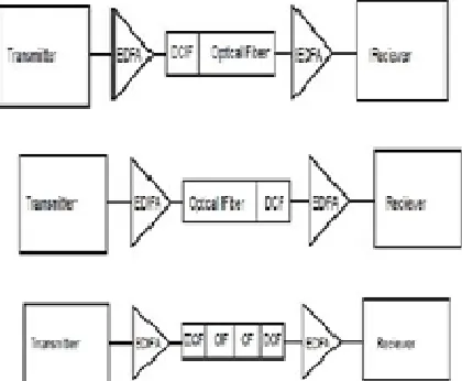
Dispersion compensation is done by three different scheme depending upon the position of DCF.
In pre compensation the DCF is place before the standard SMF to compensate the positive dispersion in standard SMF In post compensation the DCF is placed after the standard SMF to compensate the positive dispersion in standard SMF.
[image:3.612.201.411.446.619.2]In symmetrical, both the combination of pre and post symmetric were used i.e. DCF is placed before as well as after the standard SMF to achieve the dispersion compensation.
Fig 2:- Different dispersion compensation schemes
II. SIMULATION SETUP
Fig1. Simulation setup of dcf
Fig2. Simulation setup of fbg
There are 16 laser sources generating optical signal of different wavelength, the channel spacing use is 0.1 THz with 0db output power.
The multiplexer consists of 16 input channels and transmitted over optical fiber channel. The transmitted channel consists of a SMF of variable length of 80,100 & 120 km and DCF of length 20 km. EDFA fiber of length 5 km are used after the DCF in order to amplify the signals.
At the receiver sides, the 1:16 demux is used to slot the signal in 16 different channels. The o/p of the demux is given to photo detector APD which converts the optical signal to electrical. Then the electrical signal is passes through low pass bessels filter having transfer function
H(s)= ( )
where ( )is a reverse Bessel polynomial from which the filter gets its name and is a frequency chosen to give the desired cutoff frequency. The filter has a low-frequency group delay of 1 . Since (0)is indeterminate by the definition of reverse Bessel
polynomials, but is a removable singularity, it is defined that (0) = lim → ( )RESULTS AND ANALYSIS
The two dispersion compensation methods have been analyzed at 80Gbps and 120 Gbps for WDM network in terms of bit error rate (BER) and Q-factor. .In order to carry out various simulations, Optisys 14.0 software has been used. We have carried out the simulations for 80 gbps and 120 gbps for 120 km, 140km and 150km . We have tabulated the simulated results of Q-factor and BER accordingly.
Compensation
Method DCF FBG
Parameter Q BER Q BER
CH-0 15.06 7.32399e-052 20.84 15.59514e-097
CH-3 15.21 7.48587e-053 24.50 5.85172e-330
CH-7 16.63 1.35511e-062 25.30 2.07746e-148
CH-11 16.43 3.38605e-061 23.50 1.30376e-172
CH-15 12.24 5.50476e-035 21.59 9.26903e-101
Table1.Comparision Table for DCF and FBG having having data rate 80 Gbps for 120 Km.
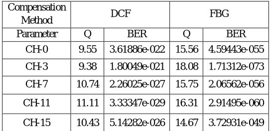
Compensation
Method DCF FBG
Parameter Q BER Q BER
CH-0 9.55 3.61886e-022 15.56 4.59443e-055
CH-3 9.38 1.80049e-021 18.08 1.71312e-073
CH-7 10.74 2.26025e-027 15.75 2.06562e-056
CH-11 11.11 3.33347e-029 16.31 2.91495e-060
[image:5.612.143.417.175.307.2]CH-15 10.43 5.14282e-026 14.67 3.72931e-049
Table 2ComparisionTable for DCF and FBG having data rate 80 Gbps for 140 Km.
Compensation
Method DCF FBG
Parameter Q BER Q BER
CH-0 7.36
5.72475e-014 13.25 1.6202e-040
CH-3 7.32
7.14255e-014 18.65
4.59684e-078
CH-7 7.75
3.57116e-015 13.15
5.28481e-040
CH-11 8.59
2.60869e-018 14.33
2.01293e-047
CH-15 8.41
1.10273e-017 13.03
3.63213e-039
[image:5.612.170.442.346.478.2]From the Table1, Table2 and Table3 it can be observed that FBG gives better performance than DCF in terms of Q-factor and BER for low data rate.
Compensation
Method DCF FBG
Parameter Q BER Q BER
CH-0 7.89 8.96372e-016 5.44 2.0649e-008
CH-3 9.16 1.56963e-020 6.21 2.3610e-010
CH-7 10.17 9.16473e-025 6.41 6.04717e-011
CH-11 7.80 1.90551e-015 6.04 6.43557e-043
CH-15 9.28 5.17475e-021 6.45 4.7791e-011
Table 4.Comparison Table of DCF and FBG for data rate 120 Gbps for 120 Km .
Compensation
Method DCF FBG
Parameter Q BER Q BER
CH-0 9.64 1.69604e-022 4.56 2.07987e-006
CH-3 7.15 2.67608e-013 5.17 1.09191e-007
CH-7 7.14 3.17626e-013 5.01 2.34719e-007
CH-11 5.91 1.17727e-009 4.81 6.7011e-007
CH-15 6.27 1.07746e-010 5.20 9.10487e-008
Table 5.ComparisionTable for DCF and FBG having data rate 120 Gbps for 140 Km .
Compensation
Method DCF FBG
Parameter Q BER Q BER
CH-0 5.91 1.11666e-009 4.08 1.884913e-005
CH-3 6.05 4.75224e-010 4.54 2.62744e-006
CH-7 4.64 1.08729e-006 4.73 9.51532e-007
CH-11 5.85 1.66291e-009 4.25 9.68896e-006
CH-15 5.67 4.25018e-009 4.77 8.22664e-007
Table 6.ComparisionTable for DCF and FBG having data rate 120 Gbps for 150 km.
[image:6.612.76.552.597.743.2]From the Table4, Table5 and Table6 it can be observed that DCF gives a better peformance in terms of Q-factor and BER for higher data rate.
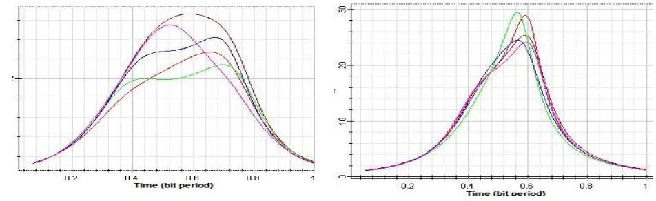
Fig: 120gbps Q-Factor of DCF Fig: Q-Factor comparison for 80gbps-120km
Fig:120gbps Q-Factor of FBG Fig: Q-Factor comparison for 120 gbps-120km.
III. CONCLUSION
In this paper, we have analyzed the 16 channel WDM system at 80 Gbps and 120 Gbps for the two different dispersion compensation methods using DCF & FBG and are compared in terms of BER and Q-factor. It was observed from simulation and results that DCF gives better performance for wide band signal whereas FBG is preferable for narrowband signals. In conclusion it is found that dispersion compensation is necessary to reduce losses and cost of the system. DCF techniques increase the total losses due non-linear effects and costs of optical transmission system where as FBG helps in decreasing the cost of the system and also have low insertion loss but have limited range. Hence we can conclude both have their advantage and disadvantage and both can be used as per the requirements to compensate dispersion.
REFERENCES
[1] Tushar Kant Panda, Dr. Nalini Kant Barapanda, Dr. Krishra Chandra Patra, Dr. M MuralidharaRao, Mrs. Padmini Mishra Performance using Fiber Bragg Grating and Dispersion Compensating Fiber of a standard fiber optic link ,Vol. 4, Issue 4, July’ 2016; ISSN: 2345 – 9808.
[2] Zou X Y, Hayee M I, H wang S M, et al. Limitations in 10Gbps WDM optical – fiber transmission when using a variety of fiber types to manage dispersion and nonlinearities[J]. Lightwave Technol., PP: 1144
[3] A Yariv, D. feke, D. M Pepper, Opt.Lett.4(1979) 52
[4] Ajeet Singh Verma1, A. K. Jaiswal2, Mukesh Kumar, An Improved Methodology for Dispersion Compensation and Synchronization in Optical Fiber Communication Networks, Volume 3
[5] Jianjun Yu, Bojun Yang, “Dispersion-allacatedsoliton technology with long amplifier spacing and long distance, “IEEE photon technollet, vol 9, pp.952-954,No. 7, 1997
[7] R.J.Nuyts, Y.K. Park, P. Gallison, Photon.Technol.Lett. 8 (1996) 1406.
[8] GiulianiG. and Alessandro D.D,“ Noise analysis of conventionaland gain-clamped semiconductor optical amplifiers,” IEEE Journal of Light wave Technology, Vol. 18, pp. 1256–1263, Sept. 2000
[9] A.K. Sharma, R.K. Sinha, R. A. Agarwala, J.Opt.FiberTechnol.4 (1998) 135. [10] Wikipedia